Embed Size (px)
Citation preview

8/2/2019 G31DE
http://slidepdf.com/reader/full/g31de 1/45
11111
G31DE
User Manual
Version 1.0Published February 2009
Copyright©2009 ASRock INC. All rights reserved.
8/2/2019 G31DE
http://slidepdf.com/reader/full/g31de 2/45
22222
Copyright Notice:Copyright Notice:Copyright Notice:Copyright Notice:Copyright Notice:
No part of this manual may be reproduced, transcribed, transmitted, or translated in
any language, in any form or by any means, except duplication of documentation by
the purchaser for backup purpose, without written consent of ASRock Inc.
Products and corporate names appearing in this manual may or may not be regis-
tered trademarks or copyrights of their respective companies, and are used only for
identification or explanation and to the owners’ benefit, without intent to infringe.
Disclaimer:Disclaimer:Disclaimer:Disclaimer:Disclaimer:
Specifications and information contained in this manual are furnished for informa-
tional use only and subject to change without notice, and should not be constructed
as a commitment by ASRock. ASRock assumes no responsibility for any errors or
omissions that may appear in this manual.
With respect to the contents of this manual, ASRock does not provide warranty of
any kind, either expressed or implied, including but not limited to the implied warran-
ties or conditions of merchantability or fitness for a particular purpose.
In no event shall ASRock, its directors, officers, employees, or agents be liable for
any indirect, special, incidental, or consequential damages (including damages for
loss of profits, loss of business, loss of data, interruption of business and the like),
even if ASRock has been advised of the possibility of such damages arising from any
defect or error in the manual or product.
This device complies with Part 15 of the FCC Rules. Operation is subject to the
following two conditions:
(1) this device may not cause harmful interference, and
(2) this device must accept any interference received, including interference that
may cause undesired operation.
CALIFORNIA, USA ONLY
The Lithium battery adopted on this motherboard contains Perchlorate, a toxic
substance controlled in Perchlorate Best Management Practices (BMP) regulations
passed by the California Legislature. When you discard the Lithium battery in
California, USA, please follow the related regulations in advance.
“Perchlorate Material-special handling may apply, see
www.dtsc.ca.gov/hazardouswaste/perchlorate”
ASRock Website: http://www.asrock.com
8/2/2019 G31DE
http://slidepdf.com/reader/full/g31de 3/45
33333
Contents Contents Contents Contents Contents
1 Introduction1 Introduction1 Introduction1 Introduction1 Introduction ............................................................................................................................................................................................................................................................... 55555
1.1 Package Contents .......................................................... 5
1.2 Specifications ................................................................ 6
1.3 Motherboard Layout........................................................ 10
1.4 I/O Panel......................................................................... 11
2 Installation2 Installation2 Installation2 Installation2 Installation ......................................................................................................................................................................................................................................................................... 1212121212
2.1 Screw Holes ................................................................... 12
2.2 Pre-installation Precautions............................................ 12
2.3 CPU Installation .............................................................. 13
2.4 Installation of Heatsink and CPU fan ............................... 15
2.5 Installation of Memory Modules (DIMM) ......................... 16
2.6 Expansion Slots (PCI and PCI Express Slots) ..................... 17
2.7 Jumpers Setup ............................................................... 18
2.8 Onboard Headers and Connectors .................................. 20
2.9 HDMI_SPDIF Header Connection Guide ......................... 24
2.10 SATAII Hard Disk Setup Guide ....................................... 25
2.11 Serial ATA (SATA) / Serial ATAII (SATAII) Hard Disks
Installation ...................................................................... 26
2.12 Driver Installation Guide .............................................. 26
2.13 Untied Overclocking Technology .................................... 263 BIOS S3 BIOS S3 BIOS S3 BIOS S3 BIOS SETUP UTILITY ETUP UTILITY ETUP UTILITY ETUP UTILITY ETUP UTILITY .................................................................................................................................................................................................................. 2727272727
3.1 Introduction..................................................................... 27
3.1.1 BIOS Menu Bar..................................................... 27
3.1.2 Navigation Keys .................................................... 28
3.2 Main Screen ................................................................... 28
3.3 Smart Screen ................................................................. 29
3.4 Advanced Screen ............................................................ 30
3.4.1 CPU Configuration ................................................ 30
3.4.2 Chipset Configuration ............................................ 32
3.4.3 ACPI Configuration ................................................ 35
3.4.4 IDE Configuration .................................................. 36
3.4.5 PCIPnP Configuration ........................................... 38
3.4.6 Floppy Configuration ............................................. 39
3.4.7 Super IO Configuration .......................................... 39
3.4.8 USB Configuration ................................................ 40
3.5 Hardware Health Event Monitoring Screen...................... 41
3.6 Boot Screen ................................................................... 42
3.6.1 Boot Settings Configuration ................................... 42
3.7 Security Screen .............................................................. 43
3.8 Exit Screen .................................................................... 44
8/2/2019 G31DE
http://slidepdf.com/reader/full/g31de 4/45
44444
4 Software Support4 Software Support4 Software Support4 Software Support4 Software Support .................................................................................................................................................................................................................. 4545454545
4.1 Install Operating System ................................................ 45
4.2 Support CD Information ................................................... 45
4.2.1 Running Support CD ............................................. 45
4.2.2 Drivers Menu ......................................................... 45
4.2.3 Utilities Menu ........................................................ 45
4.2.4 Contact Information ............................................... 45
8/2/2019 G31DE
http://slidepdf.com/reader/full/g31de 5/45
55555
Chapter 1 Introduction Chapter 1 Introduction Chapter 1 Introduction Chapter 1 Introduction Chapter 1 Introduction Thank you for purchasing ASRock G31DE motherboard, a reliable motherboard pro-
duced under ASRock’s consistently stringent quality control. It delivers excellent perfor-
mance with robust design conforming to ASRock’s commitment to quality and endurance.
In this manual, chapter 1 and 2 contain introduction of the motherboard and step-by-step
guide to the hardware installation. Chapter 3 and 4 contain the configuration guide to
BIOS setup and information of the Support CD.
Because the motherboard specifications and the BIOS software might be
updated, the content of this manual will be subject to change without
notice. In case any modifications of this manual occur, the updated
version will be available on ASRock website without further notice. You
may find the latest VGA cards and CPU support lists on ASRock website
as well. ASRock website http://www.asrock.com
If you require technical support related to this motherboard, please visit
our website for specific information about the model you are using.
www.asrock.com/support/index.asp
1.1 P1.1 P1.1 P1.1 P1.1 Pack ack ack ack ack age Contentsage Contentsage Contentsage Contentsage Contents
ASRockG31DE Motherboard
(ATX Form Factor: 12.0-in x 7.5-in, 30.5 cm x 19.1 cm)
ASRock G31DE Quick Installation Guide
ASRockG31DE Support CD
One 80-conductor Ultra ATA 66/100 IDE Ribbon Cable
One Serial ATA (SATA) Data Cable (Optional)
One Serial ATA (SATA) HDD Power Cable (Optional)
One I/O Panel Shield
8/2/2019 G31DE
http://slidepdf.com/reader/full/g31de 6/45
66666
1.21 .21.21 .21 .2 SpecificationsSpecificationsSpecificationsSpecificationsSpecifications
Platform - ATX Form Factor: 12.0-in x 7.5-in, 30.5 cm x 19.1 cm
CPU - LGA 775 for Intel® CoreTM 2 Extreme / CoreTM 2 Quad / CoreTM
2 Duo / Pentium® Dual Core / Celeron® Dual Core / Celeron®,
supporting Penryn Quad Core Yorkfield and Dual Core
Wolfdale processors
- Compatible with all FSB1600/1333/1066/800MHz CPUs
(see CAUTION 1)
- Supports Hyper-Threading Technology (see CAUTION 2)
- Supports Untied Overclocking Technology (see CAUTION 3)
- Supports EM64T CPU
Chipset - Northbridge: Intel® G31
- Southbridge: Intel® ICH7
Memory - Dual Channel DDR2 Memory Technology (see CAUTION 4)
- 2 x DDR2 DIMM slots
- Supports DDR2 1066/800/667 non-ECC, un-buffered memory
(see CAUTION 5)
- Max. capacity of system memory: 8GB (see CAUTION 6)
Expansion Slot - 1 x PCI Express x16 slot
- 2 x PCI Express x1 slots
- 3 x PCI slotsGraphics - Intel® Graphics Media Accelerator 3100
- Pixel Shader 2.0, DirectX 9.0
- Max. shared memory 384MB (see CAUTION 7)
Audio - 5.1 CH Windows® VistaTM Premium Level HD Audio
(Realtek ALC662 Audio Codec)
LAN - PCIE x1 Gigabit LAN 10/100/1000 Mb/s
- Realtek RTL8111DL
- Supports Wake-On-LAN
Rear Panel I/O I/O Panel
- 1 x PS/2 Mouse Port
- 1 x PS/2 Keyboard Port
- 1 x Serial Port: COM1
- 1 x VGA Port
- 4 x Ready-to-Use USB 2.0 Ports
- 1 x RJ-45 LAN Port with LED (ACT/LINK LED and SPEED LED)
- HD Audio Jack: Line in / Front Speaker / Microphone
8/2/2019 G31DE
http://slidepdf.com/reader/full/g31de 7/45
77777
Connector - 4 x SATAII 3.0 Gb/s connectors (No Support for RAID and
“Hot Plug” functions) (see CAUTION 8)
- 1 x ATA100 IDE connector (supports 2 x IDE devices)
- 1 x Floppy connector
- 1 x IR header
- 1 x Print port header
- 1 x HDMI_SPDIF header
- CPU/Chassis/Power FAN connector - 24 pin ATX power connector
- 8 pin 12V power connector
- CD in header
- Front panel audio connector
- 2 x USB 2.0 headers (support 4 USB 2.0 ports)
(see CAUTION 9)
BIOS Feature - 4Mb AMI BIOS
- AMI Legal BIOS
- Supports “Plug and Play”
- ACPI 1.1 Compliance Wake Up Events
- Supports jumperfree
- SMBIOS 2.3.1 Support
- CPU, VCCM Voltage Multi-adjustment
- Supports Smart BIOS
Support CD - Drivers, Utilities, AntiVirus Software (Trial Version)
Unique Feature - ASRock OC Tuner (see CAUTION 10)
- Intelligent Energy Saver (see CAUTION 11)
- Instant Boot
- Hybrid Booster:
- CPU Frequency Stepless Control (see CAUTION 12)
- ASRock U-COP (see CAUTION 13)
- Boot Failure Guard (B.F.G.)
Hardware - CPU Temperature Sensing
Monitor - Chassis Temperature Sensing
- CPU/Chassis/Power Fan Tachometer
- CPU Quiet Fan
- Voltage Monitoring: +12V, +5V, +3.3V, Vcore
OS - Microsoft® Windows® 2000 / XP / XP 64-bit / VistaTM /
VistaTM 64-bit compliant
Certifications - FCC, CE, WHQL
* For detailed product information, please visit our website: http://www.asrock.com
8/2/2019 G31DE
http://slidepdf.com/reader/full/g31de 8/45
88888
CAUTION!
1. FSB1600-CPU will operate in overclocking mode. Under this situation,
PCIE frequency will also be overclocked to 120MHz.
2. About the setting of “Hyper Threading Technology”, please check page
32.
3. This motherboard supports Untied Overclocking Technology. Please read
“Untied Overclocking Technology” on page 26 for details.
4. This motherboard supports Dual Channel Memory Technology. Before you
implement Dual Channel Memory Technology, make sure to read the
installation guide of memory modules on page 16 for proper installation.
5. Please check the table below for the CPU FSB frequency and its
corresponding memory support frequency.
CPU FSB Frequency Memory Support Frequency
1600 DDR2 800, DDR2 1066 *
1333 DDR2 667, DDR2 800, DDR2 1066 *
1066 DDR2 667, DDR2 800, DDR2 1066
800 DDR2 667, DDR2 800
* When you use a FSB1600-CPU on this motherboard, it will run at
DDR2 960 if you adopt a DDR2 1066 memory module. When you use
a FSB1333-CPU on this motherboard, it will run at DDR2 1000 if you
adopt a DDR2 1066 memory module.
* DDR2 1066 memory module will operate in overclocking mode.
6. Due to the operating system limitation, the actual memory size may be
less than 4GB for the reservation for system usage under Windows® XP
and Windows® VistaTM. For Windows® XP 64-bit and Windows® VistaTM 64-
bit with 64-bit CPU, there is no such limitation.
7. The maximum shared memory size is defined by the chipset vendor and
is subject to change. Please check Intel® website for the latest information.
8. Before installing SATAII hard disk to SATAII connector, please read the “SATAII
Hard Disk Setup Guide” on page 25 to adjust your SATAII hard disk drive to
SATAII mode. You can also connect SATA hard disk to SATAII connector directly.
9. Power Management for USB 2.0 works fine under Microsoft® Windows®
VistaTM 64-bit / VistaTM / XP 64-bit / XP SP1 or SP2 / 2000 SP4.
10. It is a user-friendly ASRock overclocking tool which allows you to surveil
your system by hardware monitor function and overclock your hardware
devices to get the best system performance under Windows ®
environment. Please visit our website for the operation procedures of
ASRock OC Tuner. ASRock website: http://www.asrock.com
WARNING
Please realize that there is a certain risk involved with overclocking, including adjusting
the setting in the BIOS, applying Untied Overclocking Technology, or using the third-
party overclocking tools. Overclocking may affect your system stability, or even
cause damage to the components and devices of your system. It should be done at
your own risk and expense. We are not responsible for possible damage caused by
overclocking.
8/2/2019 G31DE
http://slidepdf.com/reader/full/g31de 9/45
99999
11. Featuring an advanced proprietary hardware and software design,
Intelligent Energy Saver is a revolutionary technology that delivers
unparalleled power savings. In other words, it is able to provide excep-
tional power saving and improve power efficiency without sacrificing
computing performance. Please visit our website for the operation pro-
cedures of Intelligent Energy Saver.
ASRock website: http://www.asrock.com
12. Although this motherboard offers stepless control, it is not recom-
mended to perform over-clocking. Frequencies other than the recom-
mended CPU bus frequencies may cause the instability of the system
or damage the CPU.13. While CPU overheat is detected, the system will automatically shutdown.
Before you resume the system, please check if the CPU fan on the
motherboard functions properly and unplug the power cord, then plug it
back again. To improve heat dissipation, remember to spray thermal
grease between the CPU and the heatsink when you install the PC
system.
8/2/2019 G31DE
http://slidepdf.com/reader/full/g31de 10/45
1010101010
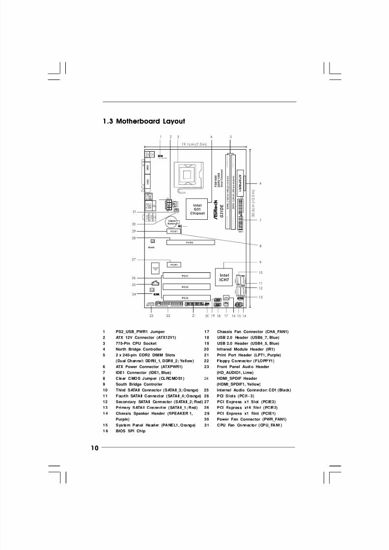
1.3 Motherboard Layout1.3 Motherboard Layout1.3 Motherboard Layout1.3 Motherboard Layout1.3 Motherboard Layout
1
P S 2_US B_P WR1
IDE1
CHA_FAN1
SPEAKER1
1
HD_AUDIO1
IntelG31Chipset
CLRCMOS1
PANEL1
HDLED RESET
PLED PWRBTN
1
CMOSBattery
4Mb
BIOS
1
AUDIOCODEC
19.1cm (7.5 in)
3 0
. 5 c m
( 1 2
. 0 i n
)
Super IO
FLOPPY1
1 2 4 5
7
6
8
9
10
12
13
14
11
15161718192223
24
25
26
27
3
2021
IntelICH7
F S B 8 0 0
D D R I I_ 1 ( 6 4 b i t ,
2 4 0
- p i n m o
d u
l e )
F S B 8 0 0
D D R I I_ 2 ( 6 4 b i t ,
2 4 0
- p i n m o
d u
l e )
S A T A I I_ 3
S A T A I I_ 1
S A T A I I_ 4
S A T A I I_ 2
PCIE1
CD1
LANPHY
USB 2.0
T: USB2
B: USB3
USB 2.0T: USB0B: USB1
Top:RJ-45
C O M 1
P S 2
M o u s e
P S 2
K e
y b o a r
d
V G A 1
T o
p :
L i n
e I n
C e n
t e r :
L i n
e O u t
B o t t o m :
M i c I n
C P U
_ F A N 1
1USB6_7
28
PCI1
PCI2
1
LP T1
ATX12V1
1HDMI_SPDIF1
1USB4_5
PCIE2
PCIE3
PCI3
IR1
1
PWR_FAN1
RoHS
F S B 1 6 0 0
D D R 2 1 0 6 6
D u a
l C
h a n n e
l
G 3 1 D E
29
30
31
1 PS2_USB_PWR1 Jumper 17 Chassis Fan Connector (CHA_FAN1)
2 ATX 12V Connector (ATX12V1) 18 USB 2.0 Header (USB6_7, Blue)
3 775-Pin CPU Socket 19 USB 2.0 Header (USB4_5, Blue)
4 North Bridge Controller 20 Infrared Module Header (IR1)
5 2 x 240-pin DDR2 DIMM Slots 21 Print Port Header (LPT1, Purple)
(Dual Channel: DDRII_1, DDRII_2; Yellow) 22 Floppy Connector (FLOPPY1)
6 ATX Power Connector (ATXPWR1) 23 Front Panel Audio Header
7 IDE1 Connector (IDE1, Blue) (HD_AUDIO1, Lime)
8 Clear CMOS Jumper (CLRCMOS1) 24 HDMI_SPDIF Header
9 South Bridge Controller (HDMI_SPDIF1, Yellow)10 Third SATAII Connector (SATAII_3; Orange) 25 Internal Audio Connector: CD1 (Black)
11 Fourth SATAII Connector (SATAII_4; Orange) 26 PCI Slots (PCI1- 3)
12 Secondary SATAII Connector (SATAII_2; Red) 27 PCI Express x1 Slot (PCIE3)
13 Primary SATAII Connector (SATAII_1; Red) 28 PCI Express x16 Slot (PCIE2)
1 4 Chassis Speaker Header (SPEAKER 1, 2 9 PCI Express x1 Slot (PCIE1)
Purple) 30 Power Fan Connector (PWR_FAN1)
15 System Panel Header (PANEL1, Orange) 31 CPU Fan Connector (CPU_FAN1)
1 6 BIOS SPI Chip
8/2/2019 G31DE
http://slidepdf.com/reader/full/g31de 11/45
1111111111
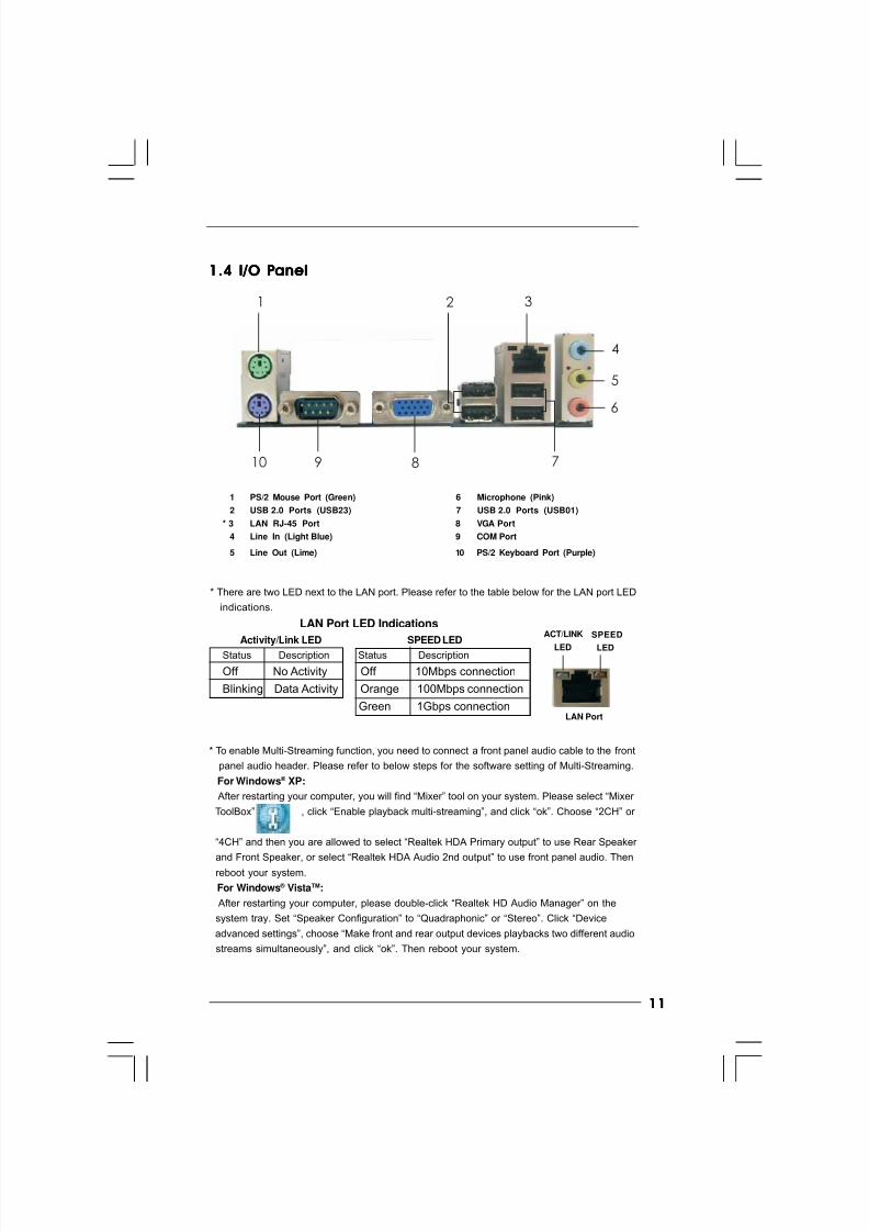
1.4 I/O P1.4 I/O P1.4 I/O P1.4 I/O P1.4 I/O Panelanelanelanelanel
1 PS/2 Mouse Port (Green) 6 Microphone (Pink)
2 USB 2.0 Ports (USB23) 7 USB 2.0 Ports (USB01)
* 3 LAN RJ-45 Port 8 VGA Port
4 Line In (Light Blue) 9 COM Port
5 Line Out (Lime) 10 PS/2 Keyboard Port (Purple)
* To enable Multi-Streaming function, you need to connect a front panel audio cable to the front
panel audio header. Please refer to below steps for the software setting of Multi-Streaming.
For Windows ® XP:
After restarting your computer, you will find “Mixer” tool on your system. Please select “Mixer
ToolBox” , click “Enable playback multi-streaming”, and click “ok”. Choose “2CH” or
“4CH” and then you are allowed to select “Realtek HDA Primary output” to use Rear Speaker
and Front Speaker, or select “Realtek HDA Audio 2nd output” to use front panel audio. Then
reboot your system.
For Windows ® VistaTM:
After restarting your computer, please double-click “Realtek HD Audio Manager” on the
system tray. Set “Speaker Configuration” to “Quadraphonic” or “Stereo”. Click “Device
advanced settings”, choose “Make front and rear output devices playbacks two different audio
streams simultaneously”, and click “ok”. Then reboot your system.
1 2
4
3
5
6
78910
LAN Port
ACT/LINK
LED
SPEED
LED
* There are two LED next to the LAN port. Please refer to the table below for the LAN port LED
indications.
LAN Port LED Indications
Activity/Link LED SPEED LED
Status Description Status Description
Off No Activity Off 10Mbps connection
Blinking Data Activity Orange 100Mbps connection
Green 1Gbps connection
8/2/2019 G31DE
http://slidepdf.com/reader/full/g31de 12/45
1212121212
Chapter 2 Installation Chapter 2 Installation Chapter 2 Installation Chapter 2 Installation Chapter 2 Installation G31DE is an ATX form factor (12.0" x 7.5", 30.5 x 19.1 cm) motherboard. Before you
install the motherboard, study the configuration of your chassis to ensure that the
motherboard fits into it.
Make sure to unplug the power cord before installing or removing the
motherboard. Failure to do so may cause physical injuries to you and
damages to motherboard components.
2.1 Screw Holes2.1 Screw Holes2.1 Screw Holes2.1 Screw Holes2.1 Screw Holes
Place screws into the holes indicated by circles to secure the motherboard to the
chassis.
Do not over-tighten the screws! Doing so may damage the motherboard.
2.2 Pre-installation Precautions2.2 Pre-installation Precautions2.2 Pre-installation Precautions2.2 Pre-installation Precautions2.2 Pre-installation Precautions
Take note of the following precautions before you install motherboard components
or change any motherboard settings.
1. Unplug the power cord from the wall socket before touching any component.
2. To avoid damaging the motherboard components due to static electricity, NEVERplace your motherboard directly on the carpet or the like. Also remember to use
a grounded wrist strap or touch a safety grounded object before you handle
components.
3. Hold components by the edges and do not touch the ICs.
4. Whenever you uninstall any component, place it on a grounded antistatic pad or
in the bag that comes with the component.
Before you install or remove any component, ensure that the power is
switched off or the power cord is detached from the power supply.
Failure to do so may cause severe damage to the motherboard, peripherals,
and/or components.
8/2/2019 G31DE
http://slidepdf.com/reader/full/g31de 13/45
1313131313
Lift Lever Up to 90°
CPU Marked Corner
Socket Marked Corner
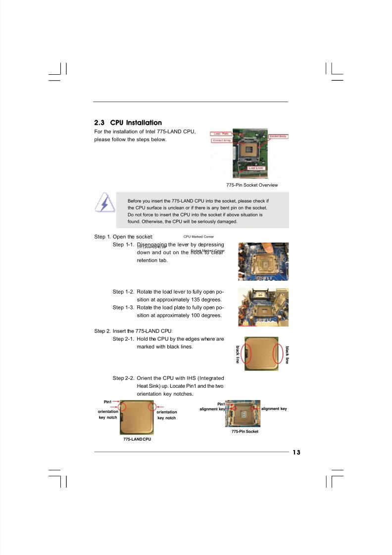
2.3 CPU Installation2.3 CPU Installation2.3 CPU Installation2.3 CPU Installation2.3 CPU Installation
For the installation of Intel 775-LAND CPU,
please follow the steps below.
Before you insert the 775-LAND CPU into the socket, please check if
the CPU surface is unclean or if there is any bent pin on the socket.
Do not force to insert the CPU into the socket if above situation is
found. Otherwise, the CPU will be seriously damaged.
Step 1. Open the socket:
Step 1-1. Disengaging the lever by depressing
down and out on the hook to clear
retention tab.
Step 1-2. Rotate the load lever to fully open po-sition at approximately 135 degrees.
Step 1-3. Rotate the load plate to fully open po-
sition at approximately 100 degrees.
Step 2. Insert the 775-LAND CPU:
Step 2-1. Hold the CPU by the edges where are
marked with black lines.
Step 2-2. Orient the CPU with IHS (Integrated
Heat Sink) up. Locate Pin1 and the two
orientation key notches.
775-Pin Socket Overview
b l a ck
l i n e
b l a ck
l i n e
775-Pin Socket
Pin1
alignment key alignment key
Pin1
orientation
key notch
orientation
key notch
775-LAND CPU
8/2/2019 G31DE
http://slidepdf.com/reader/full/g31de 14/45
1414141414
For proper inserting, please ensure to match the two orientation key
notches of the CPU with the two alignment keys of the socket.
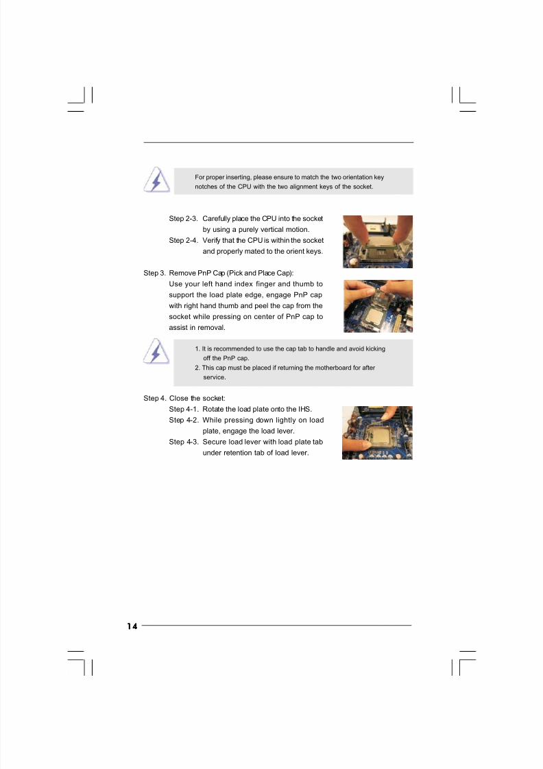
Step 2-3. Carefully place the CPU into the socket
by using a purely vertical motion.
Step 2-4. Verify that the CPU is within the socket
and properly mated to the orient keys.
Step 3. Remove PnP Cap (Pick and Place Cap):
Use your left hand index finger and thumb to
support the load plate edge, engage PnP cap
with right hand thumb and peel the cap from the
socket while pressing on center of PnP cap to
assist in removal.
1. It is recommended to use the cap tab to handle and avoid kicking
off the PnP cap.
2. This cap must be placed if returning the motherboard for after
service.
Step 4. Close the socket:
Step 4-1. Rotate the load plate onto the IHS.
Step 4-2. While pressing down lightly on load
plate, engage the load lever.
Step 4-3. Secure load lever with load plate tab
under retention tab of load lever.
8/2/2019 G31DE
http://slidepdf.com/reader/full/g31de 15/45
1515151515
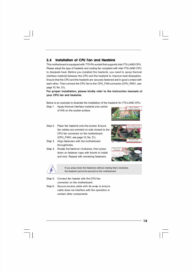
2.42. 42.42. 42.4 Installation of CPU Fan and Heatsink Installation of CPU Fan and Heatsink Installation of CPU Fan and Heatsink Installation of CPU Fan and Heatsink Installation of CPU Fan and Heatsink
This motherboard is equipped with 775-Pin socket that supports Intel 775-LAND CPU.
Please adopt the type of heatsink and cooling fan compliant with Intel 775-LAND CPU
to dissipate heat. Before you installed the heatsink, you need to spray thermal
interface material between the CPU and the heatsink to improve heat dissipation.
Ensure that the CPU and the heatsink are securely fastened and in good contact with
each other. Then connect the CPU fan to the CPU_FAN connector (CPU_FAN1, see
page 10, No. 31).
For proper installation, please kindly refer to the instruction manuals of
your CPU fan and heatsink.
Below is an example to illustrate the installation of the heatsink for 775-LAND CPU.
Step 1. Apply thermal interface material onto center
of IHS on the socket surface.
Step 2. Place the heatsink onto the socket. Ensure
fan cables are oriented on side closest to the
CPU fan connector on the motherboard
(CPU_FAN1, see page 10, No. 31).
Step 3. Align fasteners with the motherboardthroughholes.
Step 4. Rotate the fastener clockwise, then press
down on fastener caps with thumb to install
and lock. Repeat with remaining fasteners.
If you press down the fasteners without rotating them clockwise,
the heatsink cannot be secured on the motherboard.
Step 5. Connect fan header with the CPU fan
connector on the motherboard.
Step 6. Secure excess cable with tie-wrap to ensure
cable does not interfere with fan operation or contact other components.
8/2/2019 G31DE
http://slidepdf.com/reader/full/g31de 16/45
1616161616
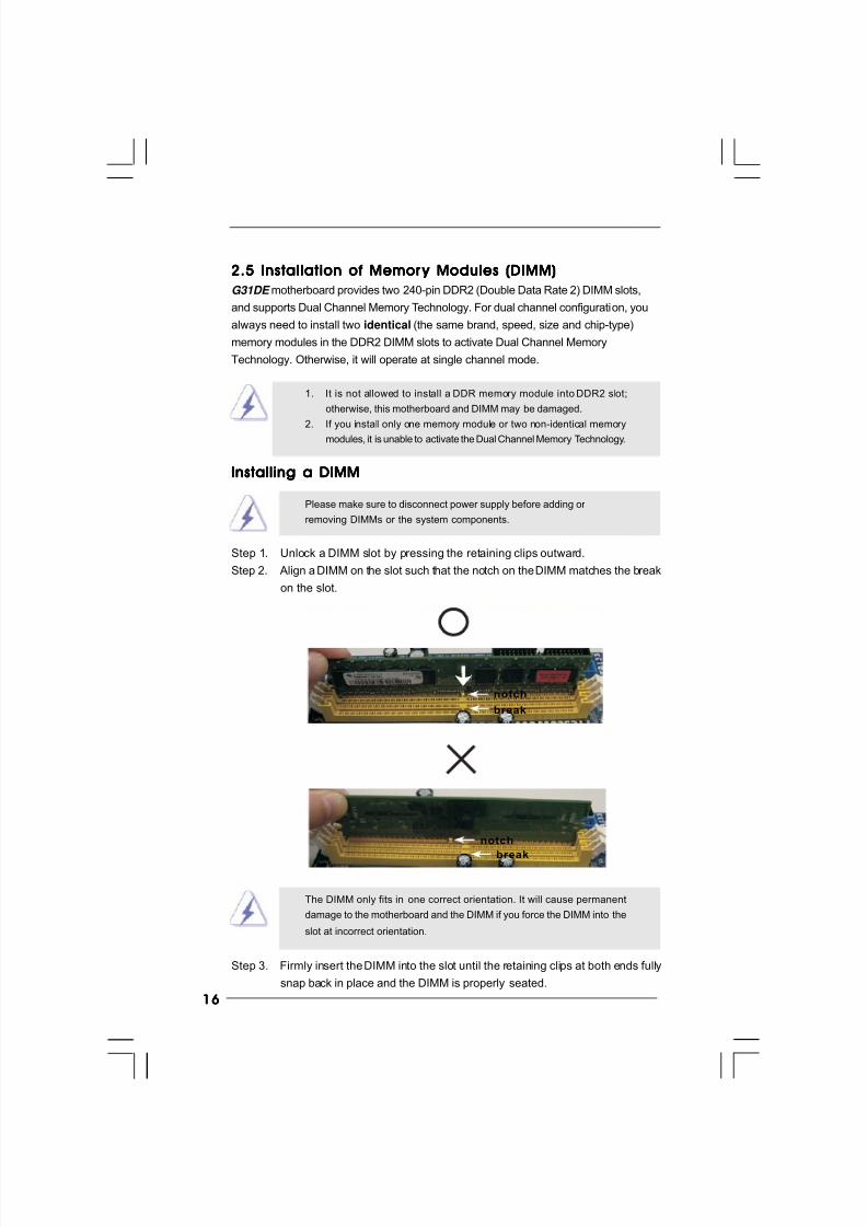
2.5 Installation of Memor2.5 Installation of Memor2.5 Installation of Memor2.5 Installation of Memor2.5 Installation of Memor y Modules (DIMM)y Modules (DIMM)y Modules (DIMM)y Modules (DIMM)y Modules (DIMM)
G31DE motherboard provides two 240-pin DDR2 (Double Data Rate 2) DIMM slots,
and supports Dual Channel Memory Technology. For dual channel configuration, you
always need to install two identical (the same brand, speed, size and chip-type)
memory modules in the DDR2 DIMM slots to activate Dual Channel Memory
Technology. Otherwise, it will operate at single channel mode.
1. It is not allowed to install a DDR memory module into DDR2 slot;
otherwise, this motherboard and DIMM may be damaged.
2. If you install only one memory module or two non-identical memory
modules, it is unable to activate the Dual Channel Memory Technology.
Installing a DIMMInstalling a DIMMInstalling a DIMMInstalling a DIMMInstalling a DIMM
Please make sure to disconnect power supply before adding or
removing DIMMs or the system components.
Step 1. Unlock a DIMM slot by pressing the retaining clips outward.
Step 2. Align a DIMM on the slot such that the notch on the DIMM matches the break
on the slot.
The DIMM only fits in one correct orientation. It will cause permanent
damage to the motherboard and the DIMM if you force the DIMM into the
slot at incorrect orientation.
Step 3. Firmly insert the DIMM into the slot until the retaining clips at both ends fully
snap back in place and the DIMM is properly seated.
notch
break
notch
break
8/2/2019 G31DE
http://slidepdf.com/reader/full/g31de 17/45
1717171717
2.6 Expansion Slots (PCI and PCI Express Slots)2.6 Expansion Slots (PCI and PCI Express Slots)2.6 Expansion Slots (PCI and PCI Express Slots)2.6 Expansion Slots (PCI and PCI Express Slots)2.6 Expansion Slots (PCI and PCI Express Slots)
There are 3 PCI slots and 3 PCI Express slots on this motherboard.
PCI slots: PCI slots are used to install expansion cards that have the 32-bit PCI
interface.
PCIE slots:
PCIE1 / PCIE3 (PCIE x1 slot) is used for PCI Express cards with x1 lane
width cards, such as Gigabit LAN card, SATA2 card, etc.
PCIE2 (PCIE x16 slot) is used for PCI Express cards with x16 lane
width graphics cards.
If you install the add-on PCI Express VGA card to PCIE2 (PCIE x16 slot),
the onboard VGA will be disabled. If you install the add-on PCI Express
VGA card to PCIE2 (PCIE x16 slot) and adjust the “Internal Graphics
Mode Select” BIOS option to [Enabled], the onboard VGA will be enabled,
and the primary screen will be onboard VGA.
Installing an expansion cardInstalling an expansion cardInstalling an expansion cardInstalling an expansion cardInstalling an expansion card
Step 1. Before installing the expansion card, please make sure that the power
supply is switched off or the power cord is unplugged. Please read the
documentation of the expansion card and make necessary hardware
settings for the card before you start the installation.
Step 2. Remove the bracket facing the slot that you intend to use. Keep the screws
for later use.
Step 3. Align the card connector with the slot and press firmly until the card is
completely seated on the slot.
Step 4. Fasten the card to the chassis with screws.
8/2/2019 G31DE
http://slidepdf.com/reader/full/g31de 18/45
1818181818
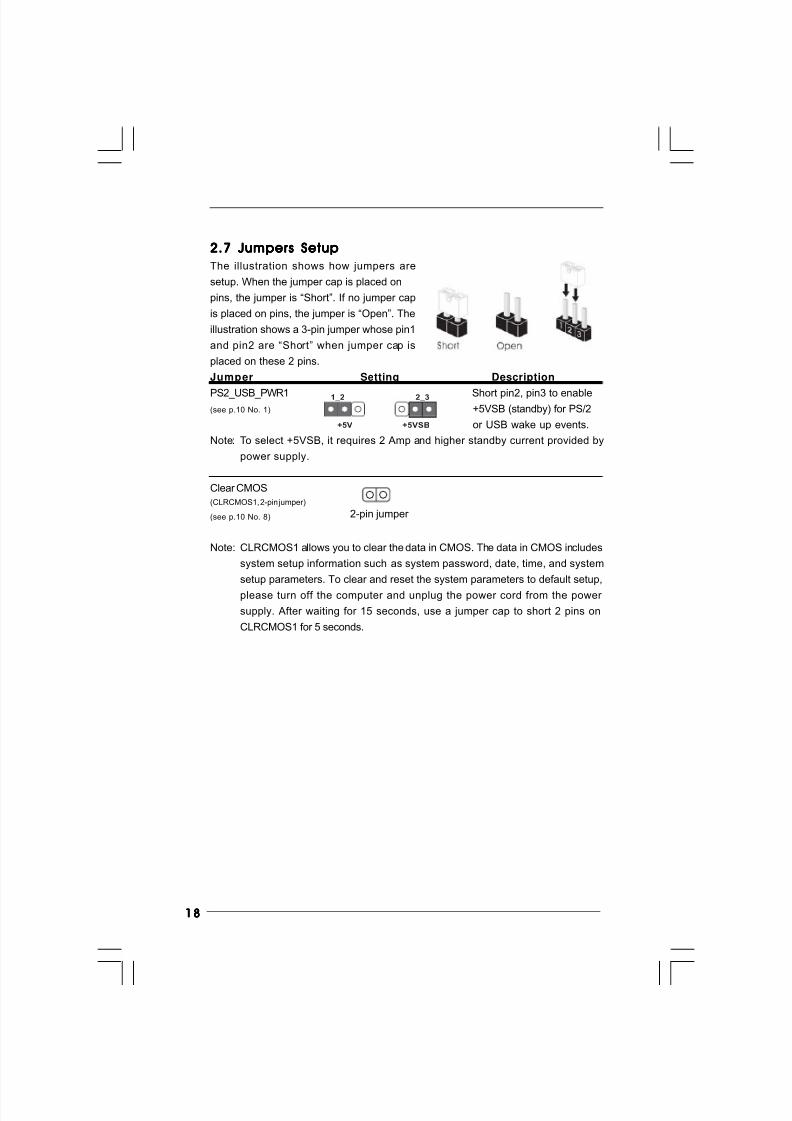
2.7 Jumpers Setup2.7 Jumpers Setup2.7 Jumpers Setup2.7 Jumpers Setup2.7 Jumpers Setup
The illustration shows how jumpers are
setup. When the jumper cap is placed on
pins, the jumper is “Short”. If no jumper cap
is placed on pins, the jumper is “Open”. The
illustration shows a 3-pin jumper whose pin1
and pin2 are “Short” when jumper cap is
placed on these 2 pins.
Jumper Setting Description
PS2_USB_PWR1 Short pin2, pin3 to enable(see p.10 No. 1) +5VSB (standby) for PS/2
or USB wake up events.
Note: To select +5VSB, it requires 2 Amp and higher standby current provided by
power supply.
Clear CMOS
(CLRCMOS1, 2-pin jumper)
(see p.10 No. 8)
Note: CLRCMOS1 allows you to clear the data in CMOS. The data in CMOS includes
system setup information such as system password, date, time, and system
setup parameters. To clear and reset the system parameters to default setup,
please turn off the computer and unplug the power cord from the power
supply. After waiting for 15 seconds, use a jumper cap to short 2 pins on
CLRCMOS1 for 5 seconds.
+5V
1_2
+5VSB
2_3
2-pin jumper
8/2/2019 G31DE
http://slidepdf.com/reader/full/g31de 19/45
1919191919
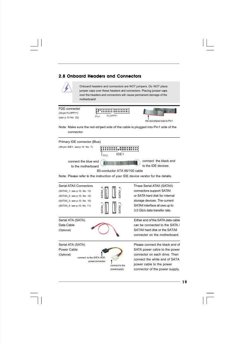
2.8 Onboard Headers and Connectors2.8 Onboard Headers and Connectors2.8 Onboard Headers and Connectors2.8 Onboard Headers and Connectors2.8 Onboard Headers and Connectors
Onboard headers and connectors are NOT jumpers. Do NOT place
jumper caps over these headers and connectors. Placing jumper caps
over the headers and connectors will cause permanent damage of the
motherboard!
FDD connector
(33-pin FLOPPY1)
(see p.10 No. 22)
Note: Make sure the red-striped side of the cable is plugged into Pin1 side of the
connector.
Primary IDE connector (Blue)
(39-pin IDE1, see p.10 No. 7)
Note: Please refer to the instruction of your IDE device vendor for the details.
Serial ATAII Connectors These Serial ATAII (SATAII)
(SATAII_1: see p.10, No. 13) connectors support SATAII
(SATAII_2: see p.10, No. 12) or SATA hard disk for internal
(SATAII_3: see p.10, No. 10) storage devices. The current
(SATAII_4: see p.10, No. 11) SATAII interface allows up to
3.0 Gb/s data transfer rate.
Serial ATA (SATA) Either end of the SATA data cable
Data Cable can be connected to the SATA /
(Optional) SATAII hard disk or the SATAII
connector on the motherboard.
Serial ATA (SATA) Please connect the black end of
Power Cable SATA power cable to the power
(Optional) connector on each drive. Then
connect the white end of SATA
power cable to the power
connector of the power supply.
FLOPPY1Pin1
the red-striped side to Pin1
connect the black end
to the IDE devices
connect the blue end
to the motherboard
80-conductor ATA 66/100 cable
IDE1PIN1
connect to the SATA HDD
power connector
connect to the
power supply
S A T A I I_ 4
S A T A I I_ 3
S A T A I I_ 2
S A T A I I_ 1
8/2/2019 G31DE
http://slidepdf.com/reader/full/g31de 20/45
2020202020
1. High Definition Audio supports Jack Sensing, but the panel wire on
the chassis must support HDA to function correctly. Please follow the
instruction in our manual and chassis manual to install your system.
2. If you use AC’97 audio panel, please install it to the front panel audio
header as below:
A. Connect Mic_IN (MIC) to MIC2_L.
B. Connect Audio_R (RIN) to OUT2_R and Audio_L (LIN) to OUT2_L.
C. Connect Ground (GND) to Ground (GND).
CD -L
GN D
GN D
CD -R
CD1
J_SENSEOUT2_L
1
MIC_RETPRESENCE#
GND
OUT2_RMIC2_R
MIC2_L
OUT_RET
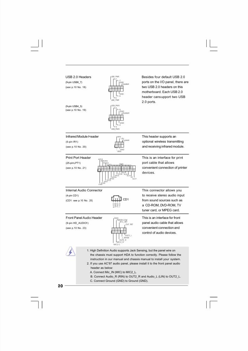
USB 2.0 Headers Besides four default USB 2.0
(9-pin USB6_7) ports on the I/O panel, there are
(see p.10 No. 18) two USB 2.0 headers on this
motherboard. Each USB 2.0
header cansupport two USB
2.0 ports.
(9-pin USB4_5)
(see p.10 No. 19)
USB_P WR
USB_P WR
P+7P-7
P+6P-6
GND
GND
DUMMY
1
USB_PW R
USB_PW R
P+5P-5
P+4P-4
GND
GND
DUMMY
1
Internal Audio Connector This connector allows you
(4-pin CD1) to receive stereo audio input
(CD1: see p.10 No. 25) from sound sources such as
a CD-ROM, DVD-ROM, TV
tuner card, or MPEG card.
Print Port Header This is an interface for print
(25-pin LPT1) port cable that allows
(see p.10 No. 21) convenient connection of printer
devices.1
AFD#
ERROR#
PINIT#GNDSLIN#
STB#
SPD0SPD1
SPD2SPD3
SPD4SPD5
SPD6SPD7
ACK#BUSY
PESLCT
Infrared Module Header This header supports an
(5-pin IR1) optional wireless transmitting
(see p.10 No. 20) and receiving infrared module.
DUMMY
GND
+5 V IRTX
IRRX
1
Front Panel Audio Header This is an interface for front
(9-pin HD_AUDIO1) panel audio cable that allows
(see p.10 No. 23) convenient connection and
control of audio devices.
8/2/2019 G31DE
http://slidepdf.com/reader/full/g31de 21/45
2121212121
+5V
DUMMY DUMMY
SPEAKER
1
GND
PW RBTN#PLED-
PLED+
DUMMY RESET#
GND
HDLED+HDLED-
1
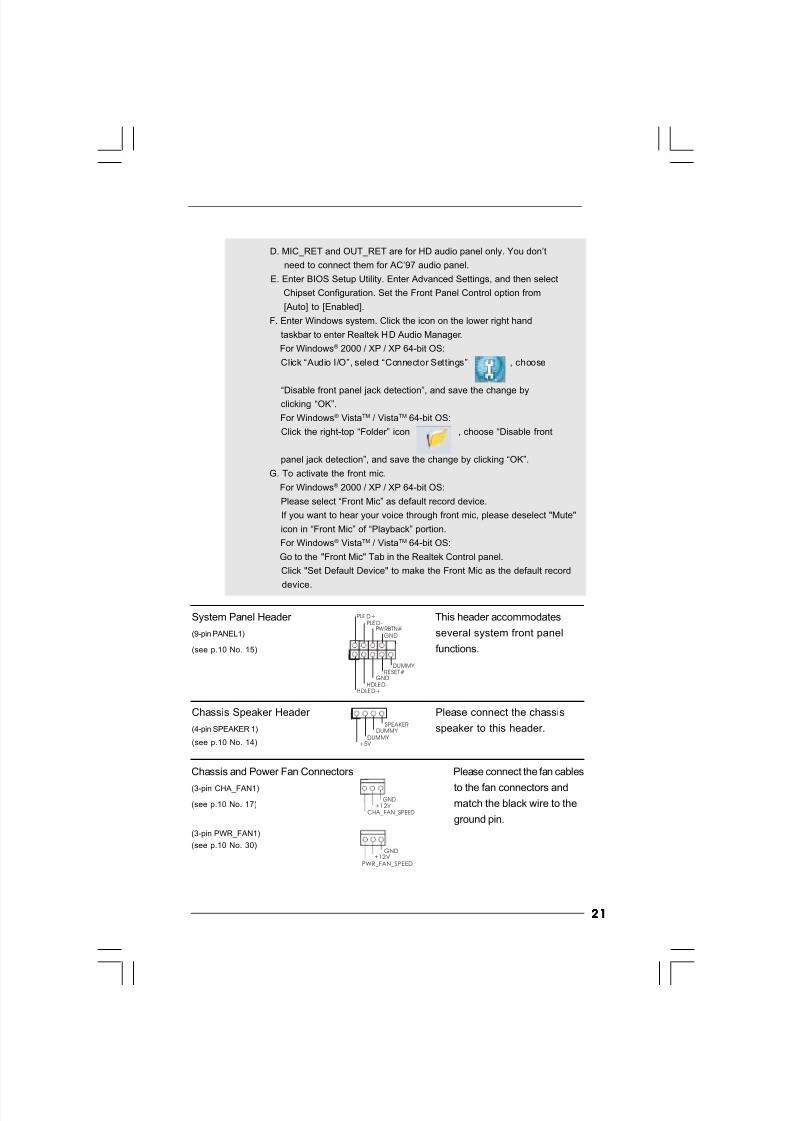
System Panel Header This header accommodates
(9-pin PANEL1) several system front panel
(see p.10 No. 15) functions.
Chassis Speaker Header Please connect the chassis
(4-pin SPEAKER 1) speaker to this header.
(see p.10 No. 14)
D. MIC_RET and OUT_RET are for HD audio panel only. You don’t
need to connect them for AC’97 audio panel.
E. Enter BIOS Setup Utility. Enter Advanced Settings, and then select
Chipset Configuration. Set the Front Panel Control option from
[Auto] to [Enabled].
F. Enter Windows system. Click the icon on the lower right hand
taskbar to enter Realtek HD Audio Manager.
For Windows® 2000 / XP / XP 64-bit OS:
Click “Audio I/O”, select “Connector Settings” , choose
“Disable front panel jack detection”, and save the change byclicking “OK”.
For Windows® VistaTM / VistaTM 64-bit OS:
Click the right-top “Folder” icon , choose “Disable front
panel jack detection”, and save the change by clicking “OK”.
G. To activate the front mic.
For Windows® 2000 / XP / XP 64-bit OS:
Please select “Front Mic” as default record device.
If you want to hear your voice through front mic, please deselect "Mute"
icon in “Front Mic” of “Playback” portion.
For Windows® VistaTM / VistaTM 64-bit OS:
Go to the "Front Mic" Tab in the Realtek Control panel.
Click "Set Default Device" to make the Front Mic as the default record
device.
Chassis and Power Fan Connectors Please connect the fan cables
(3-pin CHA_FAN1) to the fan connectors and
(see p.10 No. 17) match the black wire to the
ground pin.
(3-pin PWR_FAN1)
(see p.10 No. 30)
GND+12 V
CHA_FAN_SPEED
GND+12V
PWR_FAN_SPEED
8/2/2019 G31DE
http://slidepdf.com/reader/full/g31de 22/45
2222222222
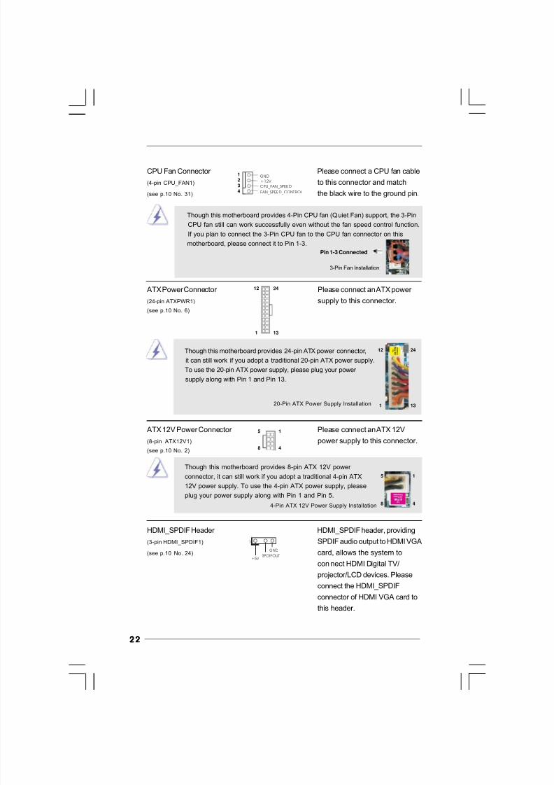
20-Pin ATX Power Supply Installation
Though this motherboard provides 4-Pin CPU fan (Quiet Fan) support, the 3-Pin
CPU fan still can work successfully even without the fan speed control function.
If you plan to connect the 3-Pin CPU fan to the CPU fan connector on this
motherboard, please connect it to Pin 1-3.
3-Pin Fan Installation
Pin 1-3 Connected
ATX Power Connector Please connect an ATX power
(24-pin ATXPWR1) supply to this connector.
(see p.10 No. 6)
Though this motherboard provides 24-pin ATX power connector,
it can still work if you adopt a traditional 20-pin ATX power supply.
To use the 20-pin ATX power supply, please plug your power
supply along with Pin 1 and Pin 13.
12
1
24
13
12
1
24
13
HDMI_SPDIF Header HDMI_SPDIF header, providing
(3-pin HDMI_SPDIF1) SPDIF audio output to HDMI VGA
(see p.10 No. 24) card, allows the system to
con nect HDMI Digital TV/
projector/LCD devices. Please
connect the HDMI_SPDIF
connector of HDMI VGA card to
this header.
1
GND
+5V SPDIFOUT
CPU Fan Connector Please connect a CPU fan cable
(4-pin CPU_FAN1) to this connector and match
(see p.10 No. 31) the black wire to the ground pin.
1234
GND
+12V
CPU_FAN_SPEED
FAN_SPEED_CONTROL
ATX 12V Power Connector Please connect an ATX 12V
(8-pin ATX12V1) power supply to this connector.
(see p.10 No. 2)
4-Pin ATX 12V Power Supply Installation
Though this motherboard provides 8-pin ATX 12V power
connector, it can still work if you adopt a traditional 4-pin ATX
12V power supply. To use the 4-pin ATX power supply, please
plug your power supply along with Pin 1 and Pin 5.
5 1
8 4
5 1
8 4
8/2/2019 G31DE
http://slidepdf.com/reader/full/g31de 23/45
2323232323
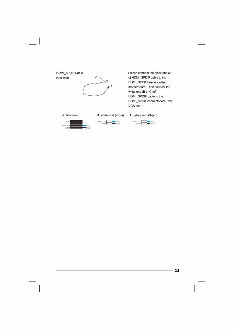
C
B
GND
+5V
SPDIFOUT blue
black
blue
black GND
SPDIFOUT blue
black GND
SPDIFOUT
A
HDMI_SPDIF Cable Please connect the black end (A)
(Optional) of HDMI_SPDIF cable to the
HDMI_SPDIF header on the
motherboard. Then connect the
white end (B or C) of
HDMI_SPDIF cable to the
HDMI_SPDIF connector of HDMI
VGA card.
A. black end B. white end (2-pin) C. white end (3-pin)
8/2/2019 G31DE
http://slidepdf.com/reader/full/g31de 24/45
2424242424
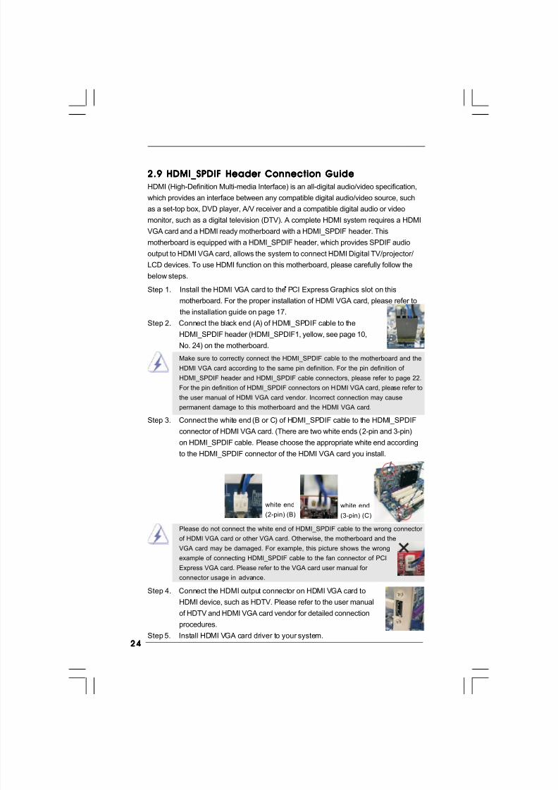
2.9 HDMI_SPDIF Header Connection Guide2.9 HDMI_SPDIF Header Connection Guide2.9 HDMI_SPDIF Header Connection Guide2.9 HDMI_SPDIF Header Connection Guide2.9 HDMI_SPDIF Header Connection Guide
HDMI (High-Definition Multi-media Interface) is an all-digital audio/video specification,
which provides an interface between any compatible digital audio/video source, such
as a set-top box, DVD player, A/V receiver and a compatible digital audio or video
monitor, such as a digital television (DTV). A complete HDMI system requires a HDMI
VGA card and a HDMI ready motherboard with a HDMI_SPDIF header. This
motherboard is equipped with a HDMI_SPDIF header, which provides SPDIF audio
output to HDMI VGA card, allows the system to connect HDMI Digital TV/projector/
LCD devices. To use HDMI function on this motherboard, please carefully follow the
below steps.•
Make sure to correctly connect the HDMI_SPDIF cable to the motherboard and the
HDMI VGA card according to the same pin definition. For the pin definition of
HDMI_SPDIF header and HDMI_SPDIF cable connectors, please refer to page 22.
For the pin definition of HDMI_SPDIF connectors on HDMI VGA card, please refer to
the user manual of HDMI VGA card vendor. Incorrect connection may cause
permanent damage to this motherboard and the HDMI VGA card.
white end
(2-pin) (B)
white end
(3-pin) (C)
Please do not connect the white end of HDMI_SPDIF cable to the wrong connector
of HDMI VGA card or other VGA card. Otherwise, the motherboard and the
VGA card may be damaged. For example, this picture shows the wrong
example of connecting HDMI_SPDIF cable to the fan connector of PCI
Express VGA card. Please refer to the VGA card user manual for
connector usage in advance.
Step 4. Connect the HDMI output connector on HDMI VGA card to
HDMI device, such as HDTV. Please refer to the user manual
of HDTV and HDMI VGA card vendor for detailed connection
procedures.
Step 5. Install HDMI VGA card driver to your system.
Step 3. Connect the white end (B or C) of HDMI_SPDIF cable to the HDMI_SPDIF
connector of HDMI VGA card. (There are two white ends (2-pin and 3-pin)
on HDMI_SPDIF cable. Please choose the appropriate white end according
to the HDMI_SPDIF connector of the HDMI VGA card you install.
Step 1. Install the HDMI VGA card to the PCI Express Graphics slot on this
motherboard. For the proper installation of HDMI VGA card, please refer to
the installation guide on page 17.
Step 2. Connect the black end (A) of HDMI_SPDIF cable to the
HDMI_SPDIF header (HDMI_SPDIF1, yellow, see page 10,
No. 24) on the motherboard.
8/2/2019 G31DE
http://slidepdf.com/reader/full/g31de 25/45
2525252525
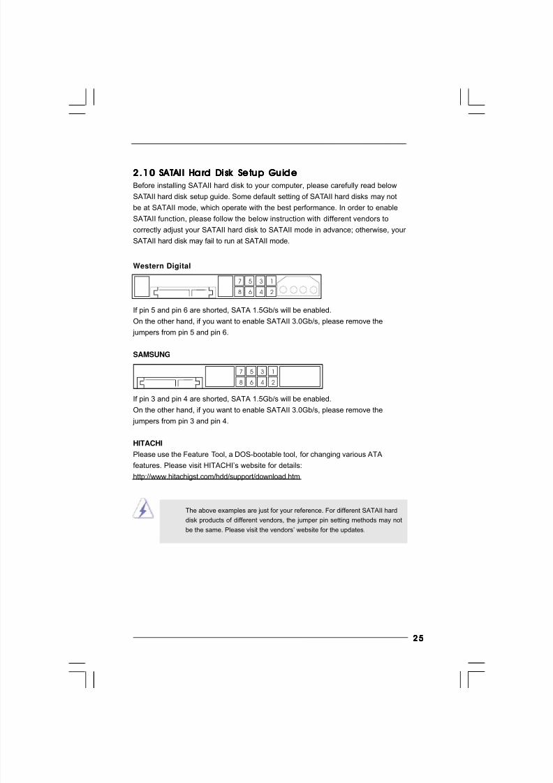
2.102.102.102.102.10 SA SA SA SA SA TTTTT AI I Hard Di sk Setup Guide AI I Hard Di sk Setup Gu ide AI I Hard Di sk Setup Guide AI I Hard Di sk Setup Gu ide AI I Ha rd Di sk Setup Gu ide
Before installing SATAII hard disk to your computer, please carefully read below
SATAII hard disk setup guide. Some default setting of SATAII hard disks may not
be at SATAII mode, which operate with the best performance. In order to enable
SATAII function, please follow the below instruction with different vendors to
correctly adjust your SATAII hard disk to SATAII mode in advance; otherwise, your
SATAII hard disk may fail to run at SATAII mode.
Western Digital
If pin 5 and pin 6 are shorted, SATA 1.5Gb/s will be enabled.
On the other hand, if you want to enable SATAII 3.0Gb/s, please remove the
jumpers from pin 5 and pin 6.
SAMSUNG
If pin 3 and pin 4 are shorted, SATA 1.5Gb/s will be enabled.
On the other hand, if you want to enable SATAII 3.0Gb/s, please remove the jumpers from pin 3 and pin 4.
HITACHI
Please use the Feature Tool, a DOS-bootable tool, for changing various ATA
features. Please visit HITACHI’s website for details:
http://www.hitachigst.com/hdd/support/download.htm
1357
2468
1357
2468
The above examples are just for your reference. For different SATAII hard
disk products of different vendors, the jumper pin setting methods may not
be the same. Please visit the vendors’ website for the updates.
8/2/2019 G31DE
http://slidepdf.com/reader/full/g31de 26/45
2626262626
2.112.112.112.112.11 Serial A Serial A Serial A Serial A Serial A TTTTT A (SA A (SA A (SA A (SA A (SA TTTTT A) / Serial A A) / Serial A A) / Serial A A) / Serial A A) / Serial A TTTTT AI I (SA AI I (SA AI I (SA AI I (SA AI I (SA TTTTT AI I) Hard Di sk s AI I) Hard Di sks AI I) Hard Di sk s AI I) Hard Di sks AI I) Hard Di sks
InstallationInstallationInstallationInstallationInstallation
This motherboard adopts Intel® ICH7 south bridge chipset that supports Serial ATA
(SATA) / Serial ATAII (SATAII) hard disks. You may install SATA / SATAII hard disks
on this motherboard for internal storage devices. This section will guide you to
install the SATA / SATAII hard disks.
STEP 1: Install the SATA / SATAII hard disks into the drive bays of your chassis.
STEP 2: Connect the SATA power cable to the SATA / SATAII hard disk.
STEP 3: Connect one end of the SATA data cable to the motherboard’s SATAII
connector.
STEP 4: Connect the other end of the SATA data cable to the SATA / SATAII hard
disk.
2.122.122.122.122.12 Driver Installation GuideDriver Installation GuideDriver Installation GuideDriver Installation GuideDriver Installation Guide
To install the drivers to your system, please insert the support CD to your optical drive
first. Then, the drivers compatible to your system can be auto-detected and listed on
the support CD driver page. Please follow the order from up to bottom side to install
those required drivers. Therefore, the drivers you install can work properly.
2.132.132.132.132.13 Untied Overclocking TUntied Overclocking TUntied Overclocking TUntied Overclocking TUntied Overclocking Technologyechnologyechnologyechnologyechnology
This motherboard supports Untied Overclocking Technology, which means during
overclocking, FSB enjoys better margin due to fixed PCI / PCIE buses. Before you
enable Untied Overclocking function, please enter “Overclock Mode” option of
BIOS setup to set the selection from [Auto] to [CPU, PCIE, Async.]. Therefore, CPU
FSB is untied during overclocking, but PCI / PCIE buses are in the fixed mode so
that FSB can operate under a more stable overclocking environment.
Please refer to the warning on page 8 for the possible overclocking risk
before you apply Untied Overclocking Technology.
8/2/2019 G31DE
http://slidepdf.com/reader/full/g31de 27/45
2727272727
Chapter 3 BIOS SETUP UTILITY Chapter 3 BIOS SETUP UTILITY Chapter 3 BIOS SETUP UTILITY Chapter 3 BIOS SETUP UTILITY Chapter 3 BIOS SETUP UTILITY
3.1 Introduction3.1 Introduction3.1 Introduction3.1 Introduction3.1 Introduction
This section explains how to use the BIOS SETUP UTILITY to configure your system.
The SPI Memory on the motherboard stores the BIOS SETUP UTILITY. You may run the
BIOS SETUP UTILITY when you start up the computer. Please press <F2> during the
Power-On-Self-Test (POST) to enter the BIOS SETUP UTILITY, otherwise, POST will
continue with its test routines.
If you wish to enter the BIOS SETUP UTILITY after POST, restart the system by press-
ing <Ctl> + <Alt> + <Delete>, or by pressing the reset button on the system chassis.You may also restart by turning the system off and then back on.
Because the BIOS software is constantly being updated, the follow-
ing BIOS setup screens and descriptions are for reference purpose
only, and they may not exactly match what you see on your screen.
3.1.13.1.13.1.13.1.13.1.1 BIOS Menu BarBIOS Menu BarBIOS Menu BarBIOS Menu BarBIOS Menu Bar
The top of the screen has a menu bar with the following selections:
Main To set up the system time/date information
Smart To load the BIOS according to your requirements
Advanced To set up the advanced BIOS featuresH/W Monitor To display current hardware status
Boot To set up the default system device to locate and load the Op-
erating System
Security To set up the security features
Exit To exit the current screen or the BIOS SETUP UTILITY
Use < > key or < > key to choose among the selections on the menu bar,
and then press <Enter> to get into the sub screen.
8/2/2019 G31DE
http://slidepdf.com/reader/full/g31de 28/45
2828282828
3.1.23.1.23.1.23.1.23.1.2 Navigation KeysNavigation KeysNavigation KeysNavigation KeysNavigation Keys
Please check the following table for the function description of each navigation
key.
Navigation Key(s) Function Description
/ Moves cursor left or right to select Screens
/ Moves cursor up or down to select items
+ / - To change option for the selected items
<Enter> To bring up the selected screen
<F1> To display the General Help Screen<F9> To load optimal default values for all the settings
<F10> To save changes and exit the BIOS SETUP UTILITY
<ESC> To jump to the Exit Screen or exit the current screen
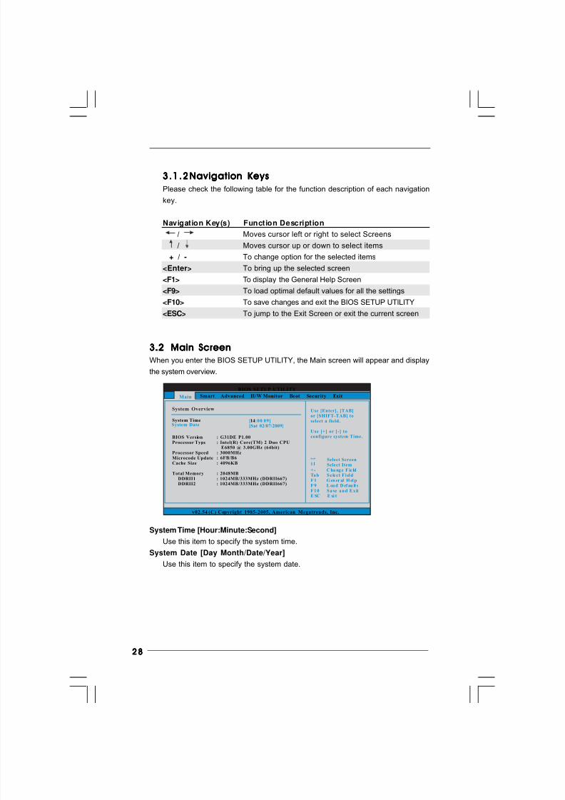
3.23. 23.23. 23.2 Main ScreenMain ScreenMain ScreenMain ScreenMain Screen
When you enter the BIOS SETUP UTILITY, the Main screen will appear and display
the system overview.
System Time [Hour:Minute:Second]
Use this item to specify the system time.
System Date [Day Month/Date/Year]
Use this item to specify the system date.
BIOS SETUP UTILITY
Main Smart H/W Monitor Boot Security ExitAdvanced
System Overview
System TimeSystem Date
[ :00:09][Sat 02/07/2009]
Use [Enter], [TAB]or [SHIFT-TAB] to
select a field.
Use [+] or [-] toconfigure system Time.
Select ScreenSelect Item
+ - C ha ng e F ie ldTa b S e le c t F i el dF 1 G en er al H el pF 9 L oa d D ef au lt sF 1 0 S a ve a n d E x itE SC E xi t
v02.54 (C) Copyright 1985-2005, American Megatrends, Inc.
14
BIOS VersionProcessor Type
Processor SpeedMicrocode UpdateCache Size
Total MemoryDDRII1DDRII2
: G31DE P1.00: Intel(R) Core(TM) 2 Duo CPU
E6850 @ 3.00GHz (64bit): 3000MHz: 6FB/B6: 4096KB
: 2048MB: 1024MB/333MHz (DDRII667): 1024MB/333MHz (DDRII667)
8/2/2019 G31DE
http://slidepdf.com/reader/full/g31de 29/45
2929292929
3.33. 33.33. 33.3 Smart ScreenSmart ScreenSmart ScreenSmart ScreenSmart Screen
In the Smart screen, you can load the BIOS setup according to your requirements.
BIOS SETUP UTILITY
Main A dv an ce d H / W M on i to r B oo t S ec ur it y E xi t
Smart Settings Exit system setupafter saving thechanges.
F10 key can be usedfor this operation.
Select ScreenSelect Item
Enter G o to Sub ScreenF 1 G en er al H el pF 9 L oa d D ef au lt sF 1 0 S a ve a n d E x itE SC E xi t
v02.54 (C) Copyright 1985-2005, American Megatrends, Inc.
Smart
Save Changes and Exit
Load BIOS DefaultsLoad Performance Setup Default (IDE/SATA)Load Power Saving Setup Default
EZ Overclocking
Load Optimized CPU OC Setting [Press Enter]
Save Changes and Exit
When you select this option, it will pop-out the following message, “Save
configuration changes and exit setup?” Select [OK] to save the changes
and exit the BIOS SETUP UTILITY.
Load BIOS Defaults
Load BIOS default values for all the setup questions. F9 key can be used
for this operation.Load Performance Setup Default (IDE/SATA)
This performance setup default may not be compatible with all system
configurations. If system boot failure occurs after loading, please resume
optimal default settings. F5 key can be used for this operation.
Load Power Saving Setup Default
Load power saving setup default. F6 key can be used for this operation.
EZ Overclocking
Load Optimized CPU OC Setting
This option appears only when you adopt Wolfdale E5000 series or E8000
series CPU. You can use this option to load the optiomized CPU overclocking
setting. The configuration options may be different according to the CPU you
adopt. Please note that overclocing may cause damage to your CPU and
motherboard. It should be done at your own risk and expense.
8/2/2019 G31DE
http://slidepdf.com/reader/full/g31de 30/45
3030303030
Setting wrong values in this section may cause
the system to malfunction.
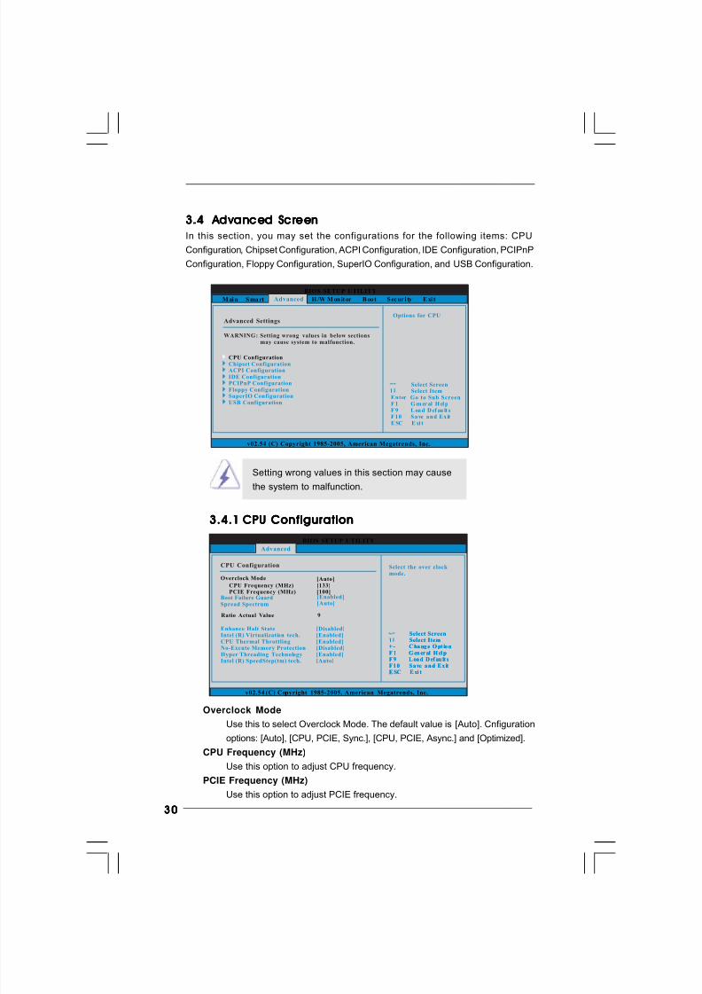
3.4.13.4.13.4.13.4.13.4.1 CPU ConfigurationCPU ConfigurationCPU ConfigurationCPU ConfigurationCPU Configuration
BIOS SETUP UTILITY
M ai n S ma rt H /W M on it or B oo t S ec ur i ty E xi t
Select ScreenSelect Item
Enter G o to Sub ScreenF 1 G en er al H el pF 9 L oa d D ef au lt sF 1 0 S a ve a n d E x itE SC E xi t
v02.54 (C) Copyright 1985-2005, American Megatrends, Inc.
Advanced
Advanced Settings
WARNING : Setting wrong values in below sectionsmay cause system to malfunction.
CPU ConfigurationChipset Configuration
IDE ConfigurationPCIPnP ConfigurationFloppy ConfigurationSuperIO ConfigurationUSB Configuration
ACPI Configuration
Options for CPU
BIOS SETUP UTILITY
CPU Configuration
CPU Frequency (MHz)PCIE Frequency (MHz)
Select the over clock mode.
Select ScreenSelect Item
+ - C ha ng e O pt io nF 1 G en er al H el pF 9 L oa d D ef au lt sF 1 0 S a ve a n d E x itE SC E xi t
v02.54 (C) Copyright 1985-2005, American Megatrends, Inc.
Advanced
Overclock Mode
[133][100]
[Auto]
Boot Failure GuardSpread Spectrum
[Enabled][Auto]
Select ScreenSelect Item
+ - C ha ng e O pt io nF 1 G en er al H el pF 9 L oa d D ef au lt sF 1 0 S a ve a n d E x itE SC E xi t
Ratio Actual Value 9
Enhance Halt StateIntel (R) Virtualization tech.
No-Excute Memory ProtectionCPU Thermal Throttling
Hyper Threading TechnologyIntel (R) SpeedStep(tm) tech.
[Disabled][Enabled][Enabled][Disabled][Enabled][Auto]
Overclock Mode
Use this to select Overclock Mode. The default value is [Auto]. Cnfiguration
options: [Auto], [CPU, PCIE, Sync.], [CPU, PCIE, Async.] and [Optimized].
CPU Frequency (MHz)
Use this option to adjust CPU frequency.
PCIE Frequency (MHz)
Use this option to adjust PCIE frequency.
3.43. 43.43. 43.4 Advanced Screen Advanced Screen Advanced Screen Advanced Screen Advanced Screen
In this section, you may set the configurations for the following items: CPU
Configuration, Chipset Configuration, ACPI Configuration, IDE Configuration, PCIPnP
Configuration, Floppy Configuration, SuperIO Configuration, and USB Configuration.
8/2/2019 G31DE
http://slidepdf.com/reader/full/g31de 31/45
3131313131
Boot Failure Guard
Enable or disable the feature of Boot Failure Guard.
Spread Spectrum
This item should always be [Auto] for better system stability.
Ratio Status
This is a read-only item, which displays whether the ratio status of this
motherboard is “Locked” or “Unlocked”. If it shows “Unlocked”, you will find
an item Ratio CMOS Setting appears to allow you changing the ratio
value of this motherboard.
Ratio Actual ValueThis is a read-only item, which displays the ratio actual value of this
motherboard.
Ratio CMOS Setting
If the ratio status is unlocked, you will find this item appear to allow you
changing the ratio value of this motherboard. If the CPU you adopt supports
EIST (Intel (R) SpeedStep(tm) tech.), and you plan to adjust the ratio value,
please disable the option “ Intel (R) SpeedStep(tm) tech.” in advance.
Enhance Halt State
All processors support the Halt State (C1). The C1 state is supported
through the native processor instructions HLT and MWAIT and requires no
hardware support from the chipset. In the C1 power state, the processor
maintains the context of the system caches.
Intel (R) Virtualization tech.
When this option is set to [Enabled], a VMM (Virtual Machine Architecture)
can utilize the additional hardware capabilities provided by Vanderpool
Technology. This option wil l be hidden if the installed CPU does not support
Intel (R) Virtualization Technology.
CPU Thermal Throttling
You may select [Enabled] to enable P4 CPU internal thermal control mecha-
nism to keep the CPU from overheated. This option will be hidden if the
current CPU does not support CPU Thermal Throttling.
No-Excute Memory Protection
No-Execution (NX) Memory Protection Technology is an enhancement to
the IA-32 Intel Architecture. An IA-32 processor with “No Execute (NX)
Memory Protection” can prevent data pages from being used by malicioussoftware to execute code. This option will be hidden if the current CPU
does not support No-Excute Memory Protection.
8/2/2019 G31DE
http://slidepdf.com/reader/full/g31de 32/45
3232323232
Please note that enabling this function may reduce CPU voltage and lead to system
stability or compatibility issue with some power supplies. Please set this item to
[Disable] if above issue occurs.
Hyper Threading Technology
To enable this feature, it requires a computer system with an Intel Pentium®
4 processor that supports Hyper-Threading technology and an operating
system that includes optimization for this technology, such as Microsoft®
Windows® XP. Set to [Enabled] if using Microsoft® Windows® XP, or Linux
kernel version 2.4.18 or higher. This option will be hidden if the installed
CPU does not support Hyper-Threading technology.
Intel (R) SpeedStep(tm) tech.
Intel (R) SpeedStep(tm) tech. is Intel’s new power saving technology.
Processor can switch between multiple frequency and voltage points toenable power savings. The default value is [Auto]. Configuration options:
[Auto], [Enabled] and [Disabled]. If you install Windows ® XP and select
[Auto], you need to set the “Power Schemes” as “Portable/Laptop” to en-
able this function. If you install Windows® VistaTM and want to enable this
function, please set this item to [Enabled]. This item will be hidden if the
current CPU does not support Intel (R) SpeedStep(tm) tech..
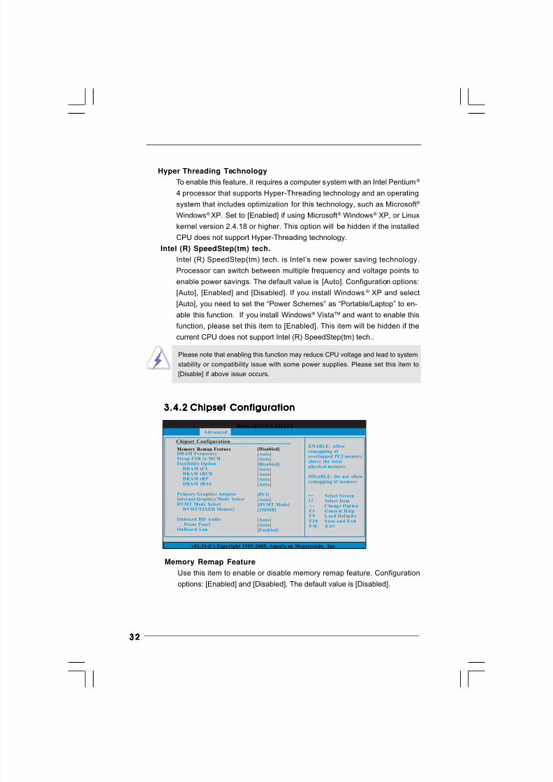
3.4.23.4.23.4.23.4.23.4.2 Chipset ConfigurationChipset ConfigurationChipset ConfigurationChipset ConfigurationChipset ConfigurationBIOS SETUP UTILITY
v02.54 (C) Copyright 1985-2005, Americ an Megatrends, Inc.
Chipset Configuration
Memory Remap FeatureDRAM FrequencyStrap FSB to MCHFlexibility Option
DRAM tCLDRAM tRCDDRAM tRPDRAM tRAS
Primary Graphics AdapterInternal Graphics Mode Select
Onboard HD AudioFront Panel
OnBoard Lan
DVMT Mode SelectDVMT/FIXED Memory
[Auto]
[Disabled]
[Auto]
[Auto]
[Auto]
[Auto]
[Auto][Auto]
[PCI][Auto]
[Auto][Enabled]
[DVMT Mode][256MB]
[Disabled]
Select ScreenSelect Item
+ - C ha ng e O pt io nF 1 G en er al H el p
F 1 0 S a ve a n d E x itE SC E xi t
F 9 L oa d D ef au lt s
ENABLE: Allowremapping of overlapped PCI memoryabove the totalphysical memory.
DISABLE: Do not allowremapping of memory.
Advanced
Memory Remap Feature
Use this item to enable or disable memory remap feature. Configuration
options: [Enabled] and [Disabled]. The default value is [Disabled].
8/2/2019 G31DE
http://slidepdf.com/reader/full/g31de 33/45
3333333333
DRAM Frequency
If [Auto] is selected, the motherboard will detect the memory module(s) in-
serted and assigns appropriate frequency automatically. You may also select
other value as operating frequency: [333MHz (DDRII667)], [400MHz (DDRII800)]
and [533MHz (DDRII1066)].
Strap FSB to MCH
Use this item to strap FSB to MCH. Configuration options: [Auto], [800], [1066]
and [1333]. The configuration options depend on the CPU you adopt. The
default value is [Auto].
Flexibility OptionThe default value of this option is [Disabled]. It will allow better tolerance for
memory compatibility when it is set to [Enabled].
DRAM tCL
Use this item to adjust the means of memory accessing. Configuration
options are [6], [5], [4], [3] and [Auto].
DRAM tRCD
This controls the latency between the DRAM active command and the
read / write command. Configuration options: [3 DRAM Clocks], [4 DRAM
Clocks], [5 DRAM Clocks], [6 DRAM Clocks] and [Auto].
DRAM tRP
This controls the idle clocks after a precharge command is issued.
Configuration options: [3 DRAM Clocks], [4 DRAM Clocks], [5 DRAM
Clocks], [6 DRAM Clocks] and [Auto].
DRAM tRAS
Thhis controls the number of DRAM clocks for TRAS. Configuration
options: [9 DRAM Clocks] to [18 DRAM Clocks] and [Auto].
Primary Graphics Adapter
This item shows the primary graphics adapter. The default value is [PCI].
Configuration options: [Onboard], [PCI] and [PCI Express].
Internal Graphics Mode Select
If you select [Auto], the onboard VGA will be automatically disabled when
you install VGA card; the onboard VGA will be enabled without the installa-
tion of any add-on VGA card. If you select [Enabled, 8MB] or [Enabled,
1MB], the onboard VGA will be enabled.
DVMT Mode SelectUse this option to adjust DVMT mode. Configuration options: [Fixed Mode]
and [DVMT Mode]. The default value is [DVMT Mode]. DVMT (Dynamic Video
Memory Technology) is an architecture that offers breakthrough perfor
mance for the motherboard through efficient memory utilization. In Fixed
mode, a fixed-size fragment of the system memory is allocated to the
graphics core. In DVMT mode, the graphics driver allocates memory as
needed for running graphics applications and is cooperatively using this
8/2/2019 G31DE
http://slidepdf.com/reader/full/g31de 34/45
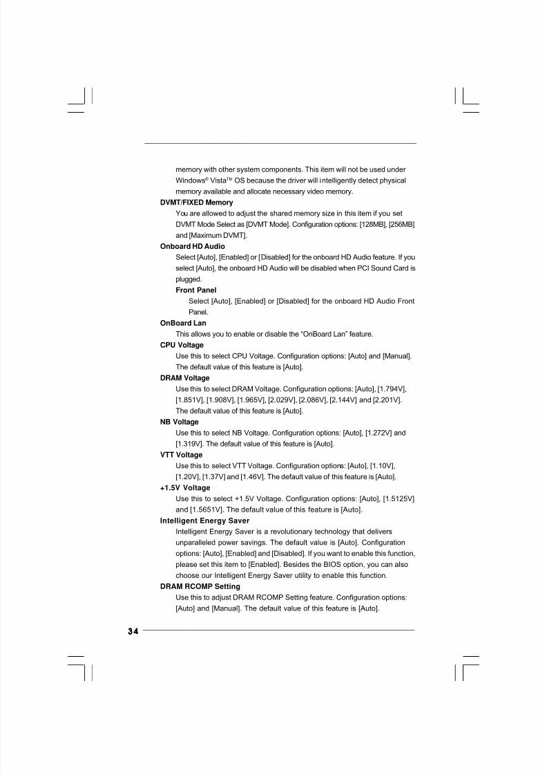
3434343434
memory with other system components. This item will not be used under
Windows® VistaTM OS because the driver will intelligently detect physical
memory available and allocate necessary video memory.
DVMT/FIXED Memory
You are allowed to adjust the shared memory size in this item if you set
DVMT Mode Select as [DVMT Mode]. Configuration options: [128MB], [256MB]
and [Maximum DVMT].
Onboard HD Audio
Select [Auto], [Enabled] or [Disabled] for the onboard HD Audio feature. If you
select [Auto], the onboard HD Audio will be disabled when PCI Sound Card isplugged.
Front Panel
Select [Auto], [Enabled] or [Disabled] for the onboard HD Audio Front
Panel.
OnBoard Lan
This allows you to enable or disable the “OnBoard Lan” feature.
CPU Voltage
Use this to select CPU Voltage. Configuration options: [Auto] and [Manual].
The default value of this feature is [Auto].
DRAM Voltage
Use this to select DRAM Voltage. Configuration options: [Auto], [1.794V],
[1.851V], [1.908V], [1.965V], [2.029V], [2.086V], [2.144V] and [2.201V].
The default value of this feature is [Auto].
NB Voltage
Use this to select NB Voltage. Configuration options: [Auto], [1.272V] and
[1.319V]. The default value of this feature is [Auto].
VTT Voltage
Use this to select VTT Voltage. Configuration options: [Auto], [1.10V],
[1.20V], [1.37V] and [1.46V]. The default value of this feature is [Auto].
+1.5V Voltage
Use this to select +1.5V Voltage. Configuration options: [Auto], [1.5125V]
and [1.5651V]. The default value of this feature is [Auto].
Intelligent Energy Saver
Intelligent Energy Saver is a revolutionary technology that delivers
unparalleled power savings. The default value is [Auto]. Configurationoptions: [Auto], [Enabled] and [Disabled]. If you want to enable this function,
please set this item to [Enabled]. Besides the BIOS option, you can also
choose our Intelligent Energy Saver utility to enable this function.
DRAM RCOMP Setting
Use this to adjust DRAM RCOMP Setting feature. Configuration options:
[Auto] and [Manual]. The default value of this feature is [Auto].
8/2/2019 G31DE
http://slidepdf.com/reader/full/g31de 35/45
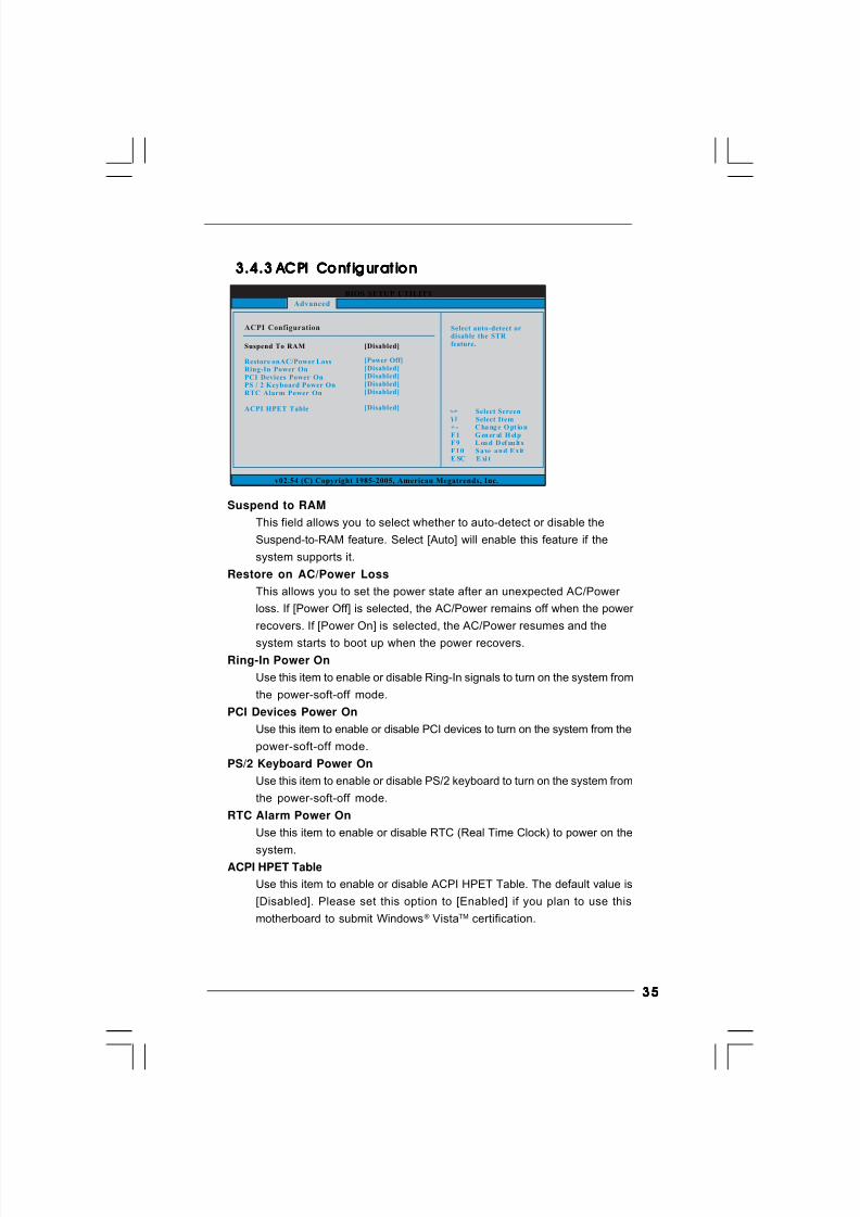
3535353535
BIOS SETUP UTILITY
ACPI Configuration Select auto-detect ordisable the STR feature.
Select ScreenSelect Item
+ - C ha ng e O pt io nF 1 G en er al H el pF 9 L oa d D ef au lt sF 1 0 S a ve a n d E x itE SC E xi t
v02.54 (C) Copyright 1985-2005, American Megatrends, Inc.
Advanced
Suspend To RAM
Restore onAC/Power LossRing-In Power OnPCI Devices Power OnPS / 2 Keyboard Power OnRTC Alarm Power On
ACPI HPET Table
[Disabled]
[Power Off][Disabled][Disabled][Disabled][Disabled]
[Disabled]
3.4.33.4.33.4.33.4.33.4.3 ACPI Conf igurat ion ACPI Conf igurat ion ACPI Conf igurat ion ACPI Conf igurat ion ACPI Conf igurat ion
Suspend to RAM
This field allows you to select whether to auto-detect or disable the
Suspend-to-RAM feature. Select [Auto] will enable this feature if the
system supports it.
Restore on AC/Power Loss
This allows you to set the power state after an unexpected AC/Power
loss. If [Power Off] is selected, the AC/Power remains off when the power
recovers. If [Power On] is selected, the AC/Power resumes and the
system starts to boot up when the power recovers.
Ring-In Power On
Use this item to enable or disable Ring-In signals to turn on the system from
the power-soft-off mode.
PCI Devices Power On
Use this item to enable or disable PCI devices to turn on the system from the
power-soft-off mode.
PS/2 Keyboard Power On
Use this item to enable or disable PS/2 keyboard to turn on the system from
the power-soft-off mode.
RTC Alarm Power On
Use this item to enable or disable RTC (Real Time Clock) to power on the
system.ACPI HPET Table
Use this item to enable or disable ACPI HPET Table. The default value is
[Disabled]. Please set this option to [Enabled] if you plan to use this
motherboard to submit Windows® VistaTM certification.
8/2/2019 G31DE
http://slidepdf.com/reader/full/g31de 36/45
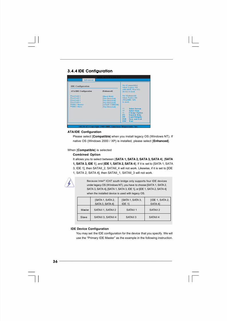
3636363636
BIOS SETUP UTILITY
IDE Configuration Set [Compatible]when Legacy OS(MS-DOS, Win NT)device is used.
Set [Enhanced]when Native OS(Win2000 / XP)is used.
v02.54 (C) Copyright 1985-2005, American Megatrends, Inc.
Advanced
ATA/IDE Configuration [Enhanced]
Select ScreenSelect Item
+ - C ha ng e O pt io nF 1 G en er al H el pF 9 L oa d D ef au lt sF 1 0 S a ve a n d E x itE SC E xi t
Select ScreenSelect Item
+ - C ha ng e O pt io nF 1 G en er al H el pF 9 L oa d D ef au lt sF 1 0 S a ve a n d E x itE SC E xi t
IDE1 MasterIDE1 Slave
SATAII 1SATAII 2SATAII 3SATAII 4
[Hard Disk][Not Detected][Not Detected][Not Detected][ATAPI CDROM][Not Detected]
3.4.43.4.43.4.43.4.43.4.4 IDE ConfigurationIDE ConfigurationIDE ConfigurationIDE ConfigurationIDE Configuration
ATA/IDE Configuration
Please select [Compatible] when you install legacy OS (Windows NT). If
native OS (Windows 2000 / XP) is installed, please select [Enhanced].
When [Compatible] is selected
Combined Option
It allows you to select between [SATA 1, SATA 2, SATA 3, SATA 4], [SATA
1, SATA 3, IDE 1], and [IDE 1, SATA 2, SATA 4]. If it is set to [SATA 1, SATA
3, IDE 1], then SATAII_2, SATAII_4 will not work. Likewise, if it is set to [IDE1, SATA 2, SATA 4], then SATAII_1, SATAII_3 will not work.
Because Intel® ICH7 south bridge only supports four IDE devices
under legacy OS (Windows NT), you have to choose [SATA 1, SATA 2,
SATA 3, SATA 4], [SATA 1, SATA 3, IDE 1], or [IDE 1, SATA 2, SATA 4]
when the installed device is used with legacy OS.
[SATA 1, SATA 2, [SATA 1, SATA 3, [IDE 1, SATA 2,
SATA 3, SATA 4] IDE 1] SATA 4]
Master SATAII 1, SATAII 2 SATAII 1 SATAII 2
Slave SATAII 3, SATAII 4 SATAII 3 SATAII 4
IDE Device Configuration
You may set the IDE configuration for the device that you specify. We will
use the “Primary IDE Master” as the example in the following instruction.
8/2/2019 G31DE
http://slidepdf.com/reader/full/g31de 37/45
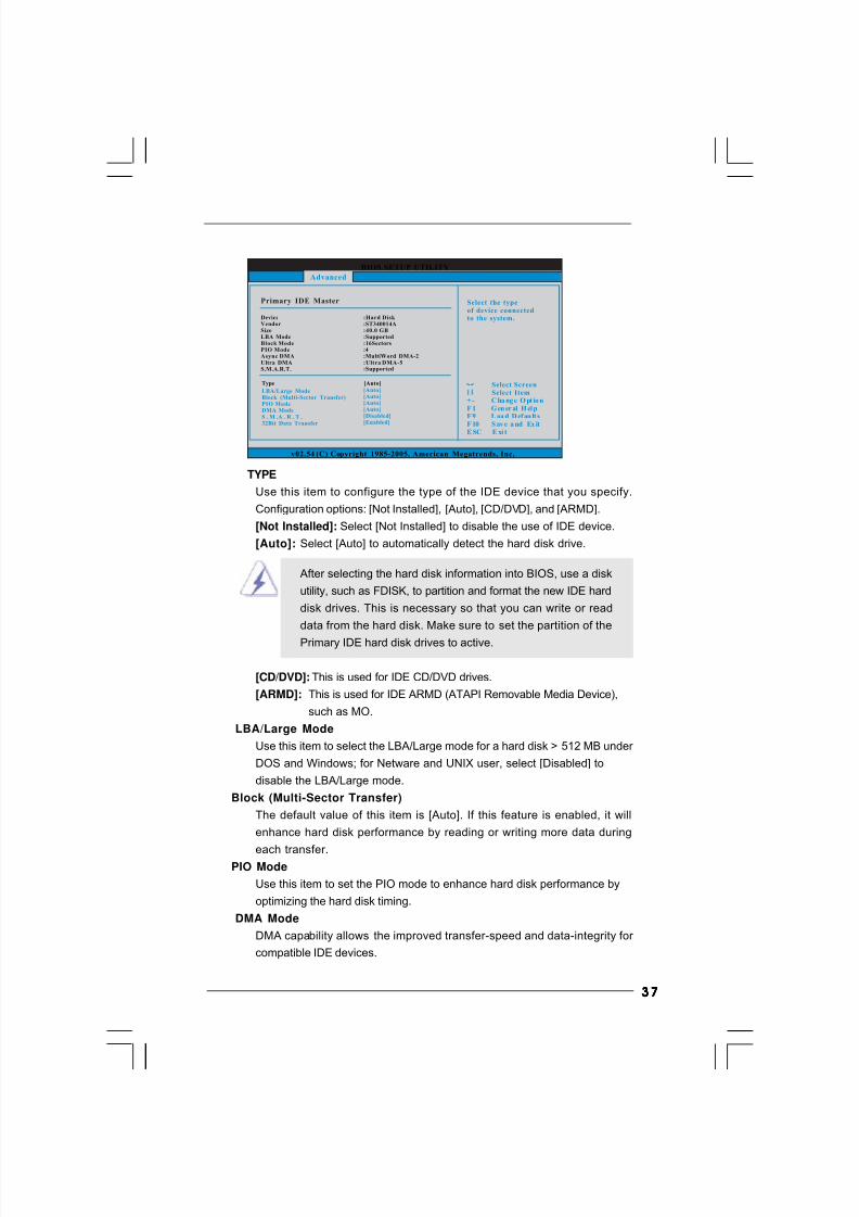
3737373737
TYPE
Use this item to configure the type of the IDE device that you specify.
Configuration options: [Not Installed], [Auto], [CD/DVD], and [ARMD].
[Not Installed]: Select [Not Installed] to disable the use of IDE device.
[Auto]: Select [Auto] to automatically detect the hard disk drive.
After selecting the hard disk information into BIOS, use a disk
utility, such as FDISK, to partition and format the new IDE hard
disk drives. This is necessary so that you can write or read
data from the hard disk. Make sure to set the partition of the
Primary IDE hard disk drives to active.
[CD/DVD]: This is used for IDE CD/DVD drives.
[ARMD]: This is used for IDE ARMD (ATAPI Removable Media Device),
such as MO.
LBA/Large Mode
Use this item to select the LBA/Large mode for a hard disk > 512 MB under
DOS and Windows; for Netware and UNIX user, select [Disabled] to
disable the LBA/Large mode.
Block (Multi-Sector Transfer)
The default value of this item is [Auto]. If this feature is enabled, it will
enhance hard disk performance by reading or writing more data during
each transfer.PIO Mode
Use this item to set the PIO mode to enhance hard disk performance by
optimizing the hard disk timing.
DMA Mode
DMA capability allows the improved transfer-speed and data-integrity for
compatible IDE devices.
BIOS SETUP UTILITY
Primary IDE Master Select the typeof device connectedto the system.
Select ScreenSelect Item
+ - C ha ng e O pt io nF 1 G en er al H el pF 9 L oa d D ef au lt s
F 10 S av e a nd Ex itE SC E xi t
v02.54 (C) Copyright 1985-2005, American Megatrends, Inc.
Advanced
Type
LBA/Large ModeBlock (Multi-Sector Transfer)PIO ModeDMA ModeS . M .A . R . T .32Bit Data Transfer
[Auto]
[Auto][Auto][Auto][Auto][Disabled][Enabled]
DeviceVendorSizeLBA ModeBlock ModePIO ModeAsync DMAUltra DMAS.M.A.R.T.
:Hard Disk :ST340014A:40.0 GB:Supported:16Sectors:4:MultiWord DMA-2:Ultra DMA-5:Supported
8/2/2019 G31DE
http://slidepdf.com/reader/full/g31de 38/45
3838383838
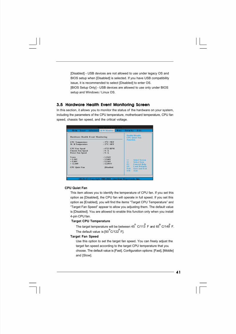
S.M.A.R.T.
Use this i tem to enable or disable the S.M.A.R.T. (Self-Monitoring, Analysis,
and Reporting Technology) feature. Configuration options: [Disabled], [Auto],
[Enabled].
32-Bit Data Transfer
Use this item to enable 32-bit access to maximize the IDE hard disk data
transfer rate.
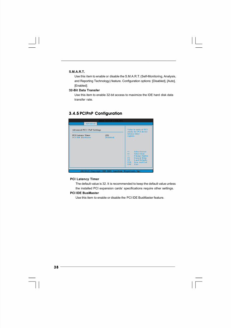
3.4.53.4.53.4.53.4.53.4.5 PCIPnP ConfigurationPCIPnP ConfigurationPCIPnP ConfigurationPCIPnP ConfigurationPCIPnP Configuration
PCI Latency Timer
The default value is 32. It is recommended to keep the default value unless
the installed PCI expansion cards’ specifications require other settings.
PCI IDE BusMaster
Use this item to enable or disable the PCI IDE BusMaster feature.
BIOS SETUP UTILITY
Advanced PCI / PnP Settings Value in units of PCIclocks for PCI devicelatency timerregister.
Select ScreenSelect Item
+ - C ha ng e O pt io nF 1 G en er al H el pF 9 L oa d D ef au lt sF 1 0 S a ve a n d E x itE SC E xi t
v02.54 (C) Copyright 1985-2005, American Megatrends, Inc.
PCI Latency TimerPCI IDE BusMaster
[32][Enabled]
Advanced
8/2/2019 G31DE
http://slidepdf.com/reader/full/g31de 39/45
3939393939
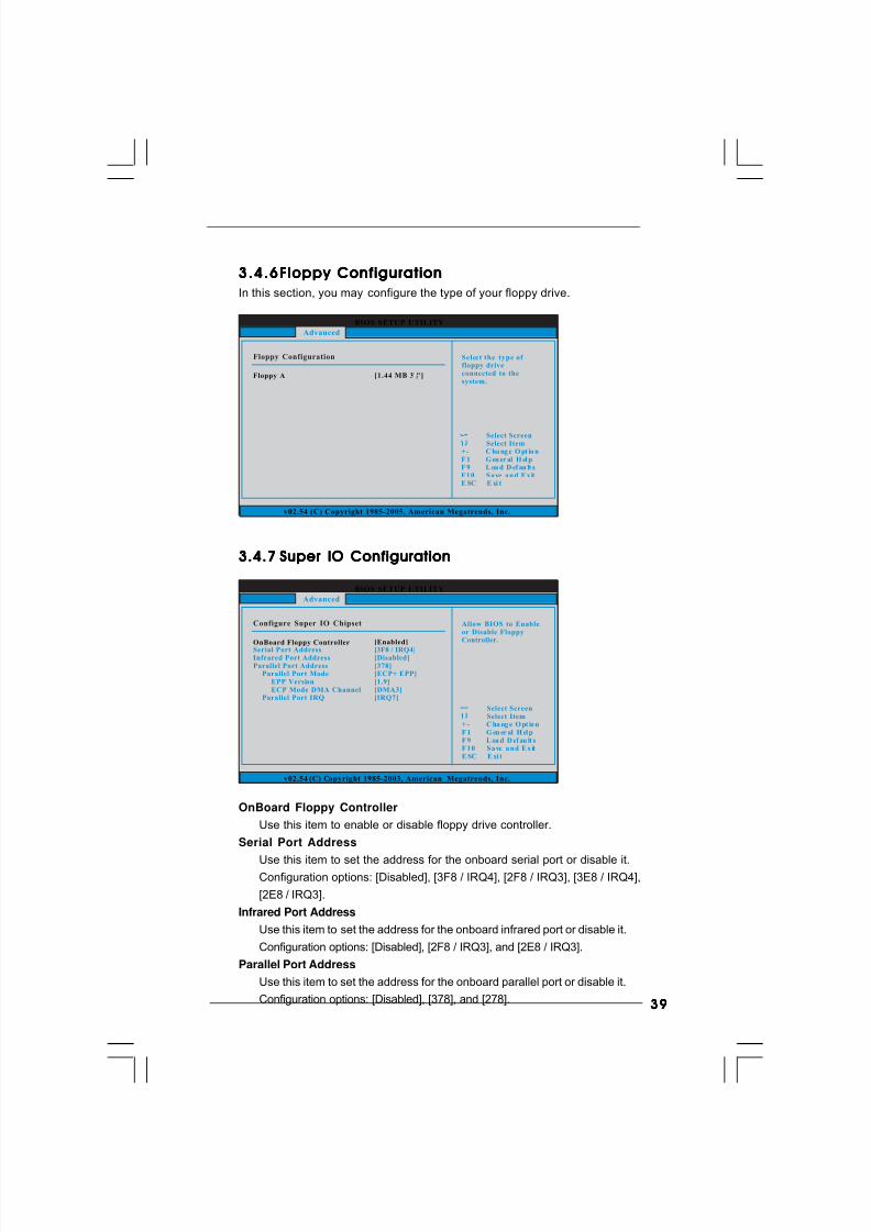
3.4.63.4.63.4.63.4.63.4.6Floppy ConfigurationFloppy ConfigurationFloppy ConfigurationFloppy ConfigurationFloppy Configuration
In this section, you may configure the type of your floppy drive.
3.4.73.4.73.4.73.4.73.4.7 Super IO ConfigurationSuper IO ConfigurationSuper IO ConfigurationSuper IO ConfigurationSuper IO Configuration
OnBoard Floppy Controller
Use this item to enable or disable floppy drive controller.
Serial Port Address
Use this item to set the address for the onboard serial port or disable it.Configuration options: [Disabled], [3F8 / IRQ4], [2F8 / IRQ3], [3E8 / IRQ4],
[2E8 / IRQ3].
Infrared Port Address
Use this item to set the address for the onboard infrared port or disable it.
Configuration options: [Disabled], [2F8 / IRQ3], and [2E8 / IRQ3].
Parallel Port Address
Use this item to set the address for the onboard parallel port or disable it.
Configuration options: [Disabled], [378], and [278].
BIOS SETUP UTILITY
Floppy Configuration Sel ect the type of floppy driveconnected to thesystem.
Select ScreenSelect Item
+ - C ha ng e O pt io nF 1 G en er al H el pF 9 L oa d D ef au lt sF 1 0 S a ve a n d E x itE SC E xi t
v02.54 (C) Copyright 1985-2005, American Megatrends, Inc.
Advanced
Floppy A [1. 44 MB 3 "]12
BIOS SETUP UTILITY
Configure Super IO Chipset Allow BIOS to Enableor Disable FloppyController.
Select ScreenSelect Item
+ - C ha ng e O pt io nF 1 G en er al H el pF 9 L oa d D ef au lt sF 1 0 S a ve a n d E x itE SC E xi t
v02.54 (C) Copyright 1985-2003, American Megatrends, Inc.
Advanced
OnBoard Floppy ControllerSerial Port AddressInfrared Port AddressParallel Port Address
Parallel Port ModeEPP VersionECP Mode DMA Channel
Parallel Port IRQ
[Enabled]
[3F8 / IRQ4][Disabled][378][ECP+ EPP][1.9][DMA3][IRQ7]
8/2/2019 G31DE
http://slidepdf.com/reader/full/g31de 40/45
4040404040
BIOS SETUP UTILITY
USB Configuration To enable or disablethe onboard USBcontrollers.
Select ScreenSelect Item
+ - C ha ng e O pt io nF 1 G en er al H el pF 9 L oa d D ef au lt sF 1 0 S a ve a n d E x itE SC E xi t
v02.54 (C) Copyright 1985-2005, American Megatrends, Inc.
Advanced
USB Controller
USB 2.0 SupportLegacy USB Support
[Enabled]
[Enabled][BIOS Setup Only]
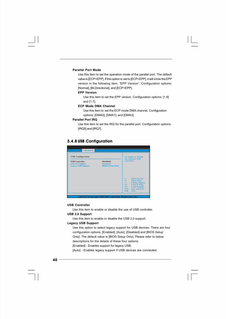
3.4.83.4.83.4.83.4.83.4.8 USB ConfigurationUSB ConfigurationUSB ConfigurationUSB ConfigurationUSB Configuration
USB Controller
Use this item to enable or disable the use of USB controller.
USB 2.0 Support
Use this item to enable or disable the USB 2.0 support.
Legacy USB SupportUse this option to select legacy support for USB devices. There are four
configuration options: [Enabled], [Auto], [Disabled] and [BIOS Setup
Only]. The default value is [BIOS Setup Only]. Please refer to below
descriptions for the details of these four options:
[Enabled] - Enables support for legacy USB.
[Auto] - Enables legacy support if USB devices are connected.
Parallel Port Mode
Use this item to set the operation mode of the parallel port. The default
value is [ECP+EPP]. If this option is set to [ECP+EPP], it will show the EPP
version in the following item, “EPP Version”. Configuration options:
[Normal], [Bi-Directional], and [ECP+EPP].
EPP Version
Use this item to set the EPP version. Configuration options: [1.9]
and [1.7].
ECP Mode DMA Channel
Use this item to set the ECP mode DMA channel. Configurationoptions: [DMA0], [DMA1], and [DMA3].
Parallel Port IRQ
Use this item to set the IRQ for the parallel port. Configuration options:
[IRQ5] and [IRQ7].
8/2/2019 G31DE
http://slidepdf.com/reader/full/g31de 41/45
4141414141
3.53. 53.53. 53.5 Hardware Health Event Monitoring ScreenHardware Health Event Monitoring ScreenHardware Health Event Monitoring ScreenHardware Health Event Monitoring ScreenHardware Health Event Monitoring Screen
In this section, it allows you to monitor the status of the hardware on your system,
including the parameters of the CPU temperature, motherboard temperature, CPU fan
speed, chassis fan speed, and the critical voltage.
BIOS SETUP UTILITY
Hardware Health Event Monitoring
Select ScreenSelect Item
F 1 G en er al H el pF 9 L oa d D ef au lt sF 1 0 S a ve a n d E x itE SC E xi t
v02.54 (C) Copyright 1985-2003, American Megatrends, Inc.
CPU TemperatureM / B Temperature
CPU Fan SpeedChassis Fan Speed
Vcore+ 3. 30V+ 5. 00V+ 12. 00V
Power Fan Speed
: 37 C / 98 F
: 4722 RPM: N / A
: 1.216V: 3.248V: 5.136V: 12.091V
: 27 C / 80 F
: N / A
M a in S mart A d va n ced B oo t S ec ur it y E xi tH/W Monitor
Enable/DisableCPU Quiet FanFunction.
CPU Quiet Fan [Disabled]
CPU Quiet Fan
This item allows you to identify the temperature of CPU fan. If you set this
option as [Disabled], the CPU fan will operate in full speed. If you set this
option as [Enabled], you will find the items “Target CPU Temperature” and
“Target Fan Speed” appear to allow you adjusting them. The default value
is [Disabled]. You are allowed to enable this function only when you install
4-pin CPU fan.
Target CPU Temperature
The target temperature will be between 45 C/113 F and 65 C/149 F.
The default value is [50 C/122 F].
Target Fan Speed
Use this option to set the target fan speed. You can freely adjust the
target fan speed according to the target CPU temperature that you
choose. The default value is [Fast]. Configuration options: [Fast], [Middle]
and [Slow].
[Disabled] - USB devices are not allowed to use under legacy OS and
BIOS setup when [Disabled] is selected. If you have USB compatibility
issue, it is recommended to select [Disabled] to enter OS.
[BIOS Setup Only] - USB devices are allowed to use only under BIOS
setup and Windows / Linux OS.
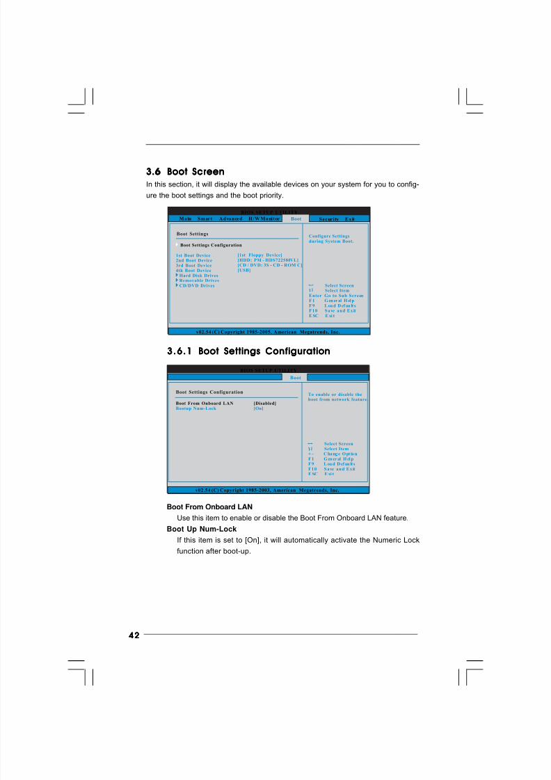
8/2/2019 G31DE
http://slidepdf.com/reader/full/g31de 42/45
4242424242
Boot From Onboard LAN
Use this item to enable or disable the Boot From Onboard LAN feature.
Boot Up Num-Lock
If this item is set to [On], it will automatically activate the Numeric Lock
function after boot-up.
3.63.63.63.63.6 Boot ScreenBoot ScreenBoot ScreenBoot ScreenBoot Screen
In this section, it will display the available devices on your system for you to config-
ure the boot settings and the boot priority.
3.6.13.6.13.6.13.6.13.6.1 Boot Settings ConfigurationBoot Settings ConfigurationBoot Settings ConfigurationBoot Settings ConfigurationBoot Settings Configuration
BIOS SETUP UTILITY
M a in S mart A d va n ced H /W M o nit or S ecurity E x it
Boot SettingsConfigure Settingsduring System Boot.
Select ScreenSelect Item
Enter G o to Sub ScreenF 1 G en er al H el pF 9 L oa d D ef au lt sF 1 0 S a ve a n d E x itE SC E xi t
v02.54 (C) Copyright 1985-2005, American Megatrends, Inc.
Boot
Boot Settings Configuration
1st Boot Device2nd Boot Device3rd Boot Device4th Boot Device
Hard Disk DrivesRemovable DrivesCD/DVD Drives
[1st Floppy Device][HDD: PM - HDS722580VL][CD / DVD: 3S - CD - ROM C][USB]
BIOS SETUP UTILITY
Boot Settings ConfigurationTo enable or disable theboot from network feature.
Select ScreenSelect Item
+ - C ha ng e O pt io nF 1 G en er al H el pF 9 L oa d D ef au lt sF 1 0 S a ve a n d E x itE SC E xi t
v02.54 (C) Copyright 1985-2003, American Megatrends, Inc.
Boot
Boot From Onboard LAN
Bootup Num-Lock
[Disabled]
[On]
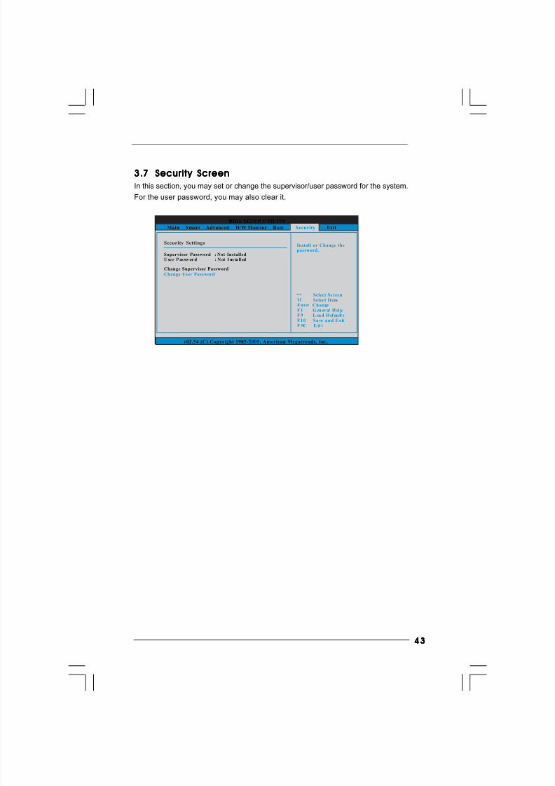
8/2/2019 G31DE
http://slidepdf.com/reader/full/g31de 43/45
4343434343
3.73.73.73.73.7 Security ScreenSecurity ScreenSecurity ScreenSecurity ScreenSecurity Screen
In this section, you may set or change the supervisor/user password for the system.
For the user password, you may also clear it.
BIOS SETUP UTILITY
Main Smart Advanced H/W Monitor Boot Exit
Install or Change thepassword.
Select ScreenSelect Item
Enter ChangeF 1 G en er al H el p
F 1 0 S a ve a n d E x itE SC E xi t
F 9 L oa d D ef au lt s
v02.54 (C) Copyright 1985-2005, American Megatrends, Inc.
Security
Change Supervisor Password
Change User Password
Security Settings
Supervisor Password : Not InstalledU se r P as sw or d : N ot I ns ta ll ed
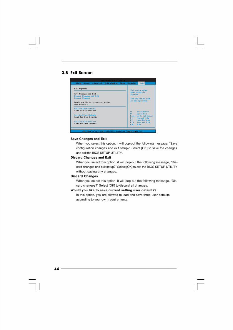
8/2/2019 G31DE
http://slidepdf.com/reader/full/g31de 44/45
4444444444
BIOS SETUP UTILITY
M ai n S ma rt A dv an ce d H /W M on it or B oo t S ec ur i ty
Exit system setupafter saving thechanges.
F10 key can be usedfor this operation.
Select ScreenSelect Item
Enter G o to Sub ScreenF 1 G en er al H el p
F 1 0 S a ve a n d E x itE SC E xi t
F 9 L oa d D ef au lt s
v02.54 (C) Copyright 1985-2005, American Megatrends, Inc.
Exit
Save Changes and Exit
Discard Changes and ExitDiscard Changes
Exit Options
Would you like to save current settinguser defaults ?
Save 1st User Defaults
Save 2nd User Defaults
Save 3rd User Defaults
Load 1st User Defaults
Load 2nd User Defaults
Load 3rd User Defaults
3.83.83.83.83.8 Exit ScreenExit ScreenExit ScreenExit ScreenExit Screen
Save Changes and Exit
When you select this option, it will pop-out the following message, “Save
configuration changes and exit setup?” Select [OK] to save the changes
and exit the BIOS SETUP UTILITY.
Discard Changes and Exit
When you select this option, it will pop-out the following message, “Dis-
card changes and exit setup?” Select [OK] to exit the BIOS SETUP UTILITY
without saving any changes.
Discard Changes
When you select this option, it will pop-out the following message, “Dis-
card changes?” Select [OK] to discard all changes.
Would you like to save current setting user defaults?
In this option, you are allowed to load and save three user defaults
according to your own requirements.
8/2/2019 G31DE
http://slidepdf.com/reader/full/g31de 45/45
4545454545
Chapter 4 Sof Chapter 4 Sof Chapter 4 Sof Chapter 4 Sof Chapter 4 Sof tware Suppor tware Suppor tware Suppor tware Suppor tware Suppor t t t t t 4.14.14.14.14.1 Install Operating SystemInstall Operating SystemInstall Operating SystemInstall Operating SystemInstall Operating System
This motherboard supports various Microsoft® Windows® operating systems: 2000 /
XP / XP 64-bit / VistaTM / VistaTM 64-bit. Because motherboard settings and hardware
options vary, use the setup procedures in this chapter for general reference only.
Refer to your OS documentation for more information.
4.24.24.24.24.2 Support CD InformationSupport CD InformationSupport CD InformationSupport CD InformationSupport CD Information
The Support CD that came with the motherboard contains necessary drivers and
useful utilities that enhance the motherboard features.
4.2.14.2.14.2.14.2.14.2.1 Running The Support CDRunning The Support CDRunning The Support CDRunning The Support CDRunning The Support CD
To begin using the support CD, insert the CD into your CD-ROM drive. The CD
automatically displays the Main Menu if “AUTORUN” is enabled in your computer.
If the Main Menu did not appear automatically, locate and double click on the
file “ASSETUP.EXE” from the BIN folder in the Support CD to display the menus.
4.2.24.2.24.2.24.2.24.2.2 Drivers MenuDrivers MenuDrivers MenuDrivers MenuDrivers Menu
The Drivers Menu shows the available devices drivers if the system detects
installed devices. Please install the necessary drivers to activate the devices.
4.2.34.2.34.2.34.2.34.2.3 Uti l i t ies MenuUti l i t ies MenuUti l i t ies MenuUti l i t ies MenuUti l i t ies Menu
The Utilities Menu shows the applications software that the motherboard
supports. Click on a specific item then follow the installation wizard to install it.
4.2.44.2.44.2.44.2.44.2.4 Contact Informat ionContact Informat ionContact Informat ionContact Informat ionContact Informat ion
If you need to contact ASRock or want to know more about ASRock, welcome
to visit ASRock’s website at http://www.asrock.com; or you may contact your
dealer for further information.


