Embed Size (px)
Citation preview

User and Installation Guide
11C10C


READ THIS WARNING BEFORE USING THE GEONAV
WARNING
THE ELECTRONIC CHART IS AN AID TO NAVIGATION DE-SIGNED TO FACILITATE THE USE OF AUTHORIZED GOV-ERNMENT CHARTS, NOT TO REPLACE THEM.ONLY OFFICIAL GOVERNMENT CHARTS AND NOTICESTO MARINERS CONTAIN ALL INFORMATION NEEDED FORTHE SAFETY OF NAVIGATION AND, AS ALWAYS, THECAPTAIN IS RESPONSIBLE FOR THEIR PROPER USE.
The use of the GEONAV implies knowledge and accep-tance of this warning by the user.
NOTE: Technical characteristics and functions described in this manual are subject tochange as a result of improvements or changes to the product.This unit runs Linux, developed under GNU General Public License. Linux is aregistered trademark by Linus Torvalds.

4
English
INTRODUCTION
The GEONAV is a chart plotter that can be interfaced with aGPS receiver, autopilot and other onboard instruments, andallows displaying the boat’s geographical position with respectto an electronic chart. Thanks to the GEONAV and aNAVIONICS Platinum™ or Gold™ electronic chart, you willnever get lost even in case of fog, bad weather or dark.
The GEONAV has been designed to allow flush mounting.Equipped with an easy-to-use keyboard, the GEONAV allowscontrolling the autopilot directly from the plotter (Easy Pilotfunction) and, thanks to the unlimited capacity of theCompactFlash™ cartridges - that can also be used on PCs aspersonal hard disks - can store a large amount of route, trackand marker data.
The GEONAV is ready for connection with the wind stationand echosounder and, thanks to windows enabled automati-cally, able to display the relevant data, if available. The con-nection supports the NMEA 0183 standard protocol.
The Route functions will allow you to plan a trip, while, thanksto the new multimedia NAVIONICS Platinum™ electroniccharts, you will always know exactly the boat’s position.NAVIONICS Platinum™ charts provide a detailed coverage ofall the most popular boating areas, offer new functions - suchas 3D display, satellite photographs, etc. - and can be used inaddition to official paper charts to obtain additional informa-tion such as the availability of port services, as well as tidesand currents data. NAVIONICS Platinum™ and Gold™ elec-tronic charts are available worldwide from authorizedNAVIONICS dealers.
When new functions are available, it will be possible to up-date the GEONAV internal software at any GEONAV dealer.
Introduction

5
English
CHARACTERISTICS
General characteristics• Easy Pilot™ function for easy and direct control of autopi-
lot• Possibility to transfer routes from one plotter station to
another through network connection• EBL and VRM functions• Multiple display of tracks• Storage of track data including significant additional in-
formation such as date, time, latitude/longitude, depth,temperature, wind data, etc.
• GOTO function (Waypoint, Port, Nearest Service, Marker,Track, Lat/Lon, R/B)
• Screen Amplifier™ function• Autozoom™ function• Overzoom™ function• 8 marker shapes, 8-character name• Reverse route function• Selectable depth units (meters, feet and fathoms)• Platinum™ electronic charts• EasyView™ function• X-Plain™ function• ARPA display function• Heading vector• CompactFlash™ cartridge• Storage of routes, tracks and markers in separate files on
CompactFlash™ cartridges• NMEA 0183 interface• Ethernet connection• Display of depth and water temperature data (if interfaced
with an echosounder)• Display of wind data (if interfaced with wind instruments)• Backlit keypad• Color LCD, transflective TFT 10.4”, daylight visible (G10C
model)• Color LCD, TFT 10.4”, enhanced contrast and brightness,
sunlight visible (G11C model)
Characteristics

6
English
• Water resistant (IPX6)
Electrical characteristics• Power supply: 9 to 36 Vd.c.• Power consumption: Max. 13 W (G10C model)• Power consumption: Max. 21 W (G11C model)• Auxiliary voltage output: 10 to 36 Vd.c.
(same as input voltage) - Max. 250 mA• Protection against: Reverse polarity
Input overvoltage (up to 40 Vd.c.)Overcurrent at auxiliary voltage out-put (over 250 mA)
• Operating temperature: 0°C to +55°C• Storage temperature: -20°C to +70°C
Memory characteristics• Up to 100 waypoints per route• Up to 5000 trackpoints (multiple tracks)• Up to 3000 markers per group• Number of routes, tracks and markers: unlimited, depend-
ing on the size of the CompactFlash™ utilised
Interface characteristics• Standard NMEA 0183 sentences
- from position sensor:GLL, VTG, GGA, RMC, GSV, ZDA, RMA, GSA, GNS,
DTM- from wind instrument:
MWV- from depth sounder:
DBT, MTW- from ARPA radar:
TLL, TTM- to autopilot:
APA, APB, XTE, RMB, BWC, GLL, VTGIf received from the GPS, the following sentences are trans-mitted: GGA, RMC, ZDA.
Characteristics

7
English
Accessories• Bracket for detachable installation• Gasket and drilling template for panel mounting• Plastic frame and drilling template for flush mounting• Power supply cable• Auxiliary power supply cable• User and Installation Guide• Protection cap• Carrying case

8
English
INSTALLATION AND PRECAUTIONS
PrecautionsWherever possible, the power supply cable shield should beconnected to the boat’s ground plate.
The GEONAV is water resistant but not waterproof, thereforeit should not be immersed totally in water.
The cartridge slot cover, located on the plotter’s right-handside, should always be kept closed and opened only whenreplacing cartridges. Make sure that the cartridge replacementis carried out as the unit is perfectly dry and that no waterenters the unit.Rear connectors, when not in use, should always be protectedby the appropriate rubber covers.
CleaningIt is recommended the use of a non-alcoholic product to cleanthe glass, since alcoholic products may damage the glass sur-face or make it opaque.
Panel mountingLocate the area where the GEONAV is to be installed, thenuse the drilling template supplied with the plotter to properlycut holes and sockets out of the instrument’s panel.
The neoprene adhesive gasket supplied must be applied tothe GEONAV rear side to avoid moisture penetration and toreduce vibrations.
Mounting screws must be 4 mm in diameter and maximum 5mm in length, plus the thickness of the panel. Do not exceedtightening the screws, in order to avoid damaging the screwseats.
Installation and Precautions

9
English
Flush mountingLocate the area where the GEONAV is to be installed, thenuse the cutting template supplied with the plotter to cut thepanel.
Apply a layer of silicone glue (the use of black colored glue isrecommended, in order to prevent the area from going yellowwhen exposed to sunlight) to the plastic frame rear part; placethe frame into the socket cut out of the panel, so that theframe edge leans against the panel.
Make sure that the frame and the panel are correctly fixed; ifnecessary, apply additional metal brackets (not supplied inthe package) as shown in the relevant figure.
Let the silicone glue dry, then apply the neoprene gasket tothe plotter rear side, insert the instrument into the frame andlock it by the screws supplied.
Do not exceed tightening the screws, in order to avoid damag-ing the screw seats.

10
English
Bracket mountingFix the bracket to the boat’s dashboard with screws 6mm indiameter.
Returning used electrical and electronic devices in EU countriesUsers of electrical and electronic devices are obligated to collect used devicesseparately. Electrical (electronic) used devices may not be disposed of together withunsorted household refuse. The separate collection is a condition for reuse, recyclingand utilisation of used electrical (electronic) devices, which ensures the protection ofresources. Electrical (electronic) used devices from private household can be re-turned free of charge. To return your used device, pleaseuse the country-specific return and collection systemsavailable to you. Electrical (electronic) devices whichare marked with one of the symbols shown may not bedisposed of with household refuse in accordance withthe EU directive.
Installation and Precautions

11
English
CONNECTIONS
Power supply and data connector (9 pins)1. Power supply
1 + VDC2 GND
2. NMEA 0183 data input3 GPS IN +4 GPS IN -
3. NMEA 0183 data output5 DATA OUT +6 DATA OUT -
4. Auxiliary output voltage (Vaux)7 Vaux+, 250mA *8 GND9 SHIELD
* Vaux voltage is the same as the plotter’s input voltage.
Auxiliary connector (7 pins)Allows connecting the GEONAV to anauxiliary instrument equipped withNMEA 0183 interface (e.g., echosounderand masthead transducer).
1. NMEA 0183 auxiliary data input1 DATA IN +2 DATA IN -
Network connector (6 pins)1. Ethernet connection
1 I AN GND 12 RX +3 RX -
Connections

12
English
4 I AN GND 25 TX +6 TX -
Connections

13
English
CARTRIDGE INSTALLATION
Installing the CompactFlash™Open the cartridge slot cover located on the plotter’s frontside.
Insert the cartridge into the appropriate slot, with the labelside towards the right, and push it down.
Close the cover exercising light pressure and check that it isperfectly closed, in order to avoid any water infiltration.
NOTE: Ensure that the cartridge is correctly inserted. Attempts to insert the cartridgeupside down with force into the slot may result in damage to the plotter or thecartridge. This type of damage is not covered by our warranty policy.
Cartridge Installation

14
English
Removing the CompactFlash™Make sure that the plotter is perfectly dry.
Open the cartridge slot cover located on the plotter’s frontside, then extract the cartridge.
WARNING: Always use CompactFlash™ cartridges certified by Navionics. Theuse of non-certified cartridges may result in improper operation of the unit.
The CompactFlash™ cartridges can be used as a mass-storagewith any personal computer, so can be the cartridge used bythe plotter. However, the plotter needs to find some free spacein the cartridge in order to work properly. Prior to use a newcartridge, always make sure that there are at least 2.5MB offree space.
WARNING: Be careful when handling the cartridge files by using the PC. Windowsallows deleting and moving files easily, therefore pay attention when using WindowsExplorer not to erase the content of the \NAVIONIC and \GEONAV folders. Damagingthe files stored in such directories may result in loss of data or improper operation ofthe unit.
Cartridge Installation

15
English
KEYBOARD
ZOOM-/ZOOM+• Increases/decreases
the chart scale• Enables/disables the
Autozoom function
JOYSTICK (right/left - up/down)• Moves the cursor across
the screen• Switches from Naviga-
tion mode to Cursormode
• Selects the options frommenus and submenus
If pressed:• Displays the chart object
attributes
ENT (ENTER):Cursor mode:• Inserts a waypoint at
the cursor’s position• Inserts a marker at the
cursor’s position (if heldpressed)
Navigation mode:• Changes the target
waypoint• Inserts a marker at the
ship’s position (if heldpressed longer)
Keyboard

16
English
Keyboard
Menu:• Confirms a selection
GOTO• Accesses the main menu and enables the MOB function (if
held pressed longer)
CLR• Cancels the setting of data in the windows• Cancels the option selection from the menuCursor mode:• Deletes all waypoints, starting from the last entered• Deletes the waypoint pointed by the cursor• Deletes the marker pointed by the cursorNavigation mode:• Deletes the whole current route
KNOB• Adjusts EBL/VRM parameters• Selects the several options from the menu windows• Scrolls letters and numbers when entering data in the
windows
If pressed:Navigation mode:• Switches from EBL to VRMMenu:• Switches from vertical to horizontal scrolling and confirms
the selection
EXIT• Cancels a selectionCursor mode:• Switches from Cursor mode to Navigation modeNavigation mode:• Turns the pages of navigation data

17
English
PWR• Switches the GEONAV
on• Opens the brightness
window• Switches the GEONAV
off (if held pressed formore than 3 seconds)

18
English
DIAGNOSTIC
The GEONAV features a diagnostic program to verify its cor-rect performance, once installed, and to detect problems thatmay occur during the use of the unit.To access the diagnostic program, hold the ENTER key pressedwhen switching the unit on.
The GEONAV will switch on and carry out automatically atest of the whole system; as soon as the memory test is com-pleted, the program will allow checking the correct operationof the unit’s parts.Press ENTER to run one test or CLR to skip it and pass to thefollowing test.
WARNING: The unit’s internal memory can be cleared by holding the CLR keypressed when switching the unit on. This operation will delete all the settings storedin the GEONAV and restore factory settings. Moreover, the routes, tracks and mark-ers not saved on the CompactFlash™ cartridge will be deleted.
NOTE: In case of damaged cartridge or abnormal power spikes, the unit might lock,requiring a power shutdown to restart. In that case, the unit can be turned off withoutthe need of detaching the power, by simply holding the PWR key pressed for morethan 10 seconds. This function is useful if the unit is panel mounted or flush mountedand the power switch cannot be easily accessed.
Diagnostic

19
English
NAVIONICS ELECTRONIC CHARTS
The GEONAV includes a built-in world map. Additional car-tography details relative to a specific area of navigation areavailable from the CompactFlash™ cartridges storingNAVIONICS Platinum™ or Gold™ electronic charts.
NAVIONICS electroniccharts contain a detailed setof symbols, similar to thoseused on official nauticalcharts.
To display the boundaries ofthe chart loaded, press theGOTO key to display themenu, select SETUP, SETCHART DETAIL and, by thejoystick, choose the optionUSER or ALL.
A small square will locatethe area covered by the car-tridge installed; position the cursor within the square andthen decrease the chart scale by the ZOOM+ key to display thedetails of the area covered by the cartridge.
The maximum detail level is obtained within port plans wherethe smallest point on screen can be equivalent to approxi-mately 1 meter, depending on the cartridge type and coverage.
Increasing/decreasing the chart scalePress the -ZOOM+ key. The current chart scale, ranging from4096 NM down to 1/8 NM, is displayed in a small windowlocated in the upper left-hand corner of the screen. The scaleunits are shown in the range window.
NAVIONICS Electronic Charts

20
English
Converting depth values into the unitssetPress GOTO to display the menu,select SETUP, DEPTH UNITS andthen set the unit desired inmeters, feet or fathoms. TheGEONAV will convert all thedepth values in the unit selected,making them appear like those re-ported in the official nauticalcharts (see the figure).
Displaying abbreviated navaid characteristicsPosition the manual cursor on the navaid symbol. A windowwill show the abbreviated characteristics relative to the navaidselected.
Description of navaid characteristics:
Displaying object attributesMove the manual cursor on top of an object on the chart, thenpress the joystick. A window will show the description of allthe objects present on the chart at the cursor’s position. Se-lect one object from this window and press the joystick toshow all of the object attributes.
NAVIONICS Electronic Charts
ABBREVIATIONS FOR LIGHT ABBREVIATIONS FOR COLOURAL alternating AM amberF fixed B blackFLL fixed and flashing BL blueFL (...) group flashing G greenFL single flashing OR orangeIQ interrupted quick R redOC single-occulting VL violetOC (...) composite group occulting W whiteQ continuous group Y yellow
ABBREVIATION FOR PERIOD ABBREVIATION FOR RANGEx x S xx seconds x x M xx nautical miles

21
English
The objects that can be queried include depth contours, depthareas, point objects (lights, navaids, landmarks, etc.), land ar-eas, spot soundings, coastlines, rocks, wrecks and, in gen-eral, any symbol present on the chart.
By querying the lights and navaids, the X-Plain™ functionwill give the description of the object in natural language,thus avoiding the use of abbreviations and symbols that aredifficult to understand.
By querying the symbols for wrecks or obstructions, NAVIONICSPlatinum™ or Gold™ charts will provide the most detailedinformation available. For example, as far as a boat is con-cerned, the chart will show its name, the wreck year, the hulllength, the depth, etc.
Chart presentation modeThe symbols used to represent the objects on the chart (buoys,lights, landmarks, etc.), as well as chart colors, can be se-lected between paper-chart International or US styles.Press GOTO to display the menu, select SETUP and PRESEN-TATION (INTER. or US).

22
English
NAVIONICS Electronic Charts
Depth contoursThis function allows the user to select the display of depthcontours; the options available are:
5m: display of contours only with depths up to 5 meters10m: display of contours only with depths up to 10 meters20m: display of contours only with depths up to 20 metersALL: all depth contours displayed
Safety contoursThis function allows the user to display the depth areas corre-sponding to the safety contour desired. The options availableare:
OFF: no depth area displayedOther values: the areas with depths up to the value selectedare displayed in shades going from darker blue (for lower depths)to lighter blue (for higher depths).
The areas whose depths are over the limit set, and thereforenavigable under safety conditions, will be displayed in white.Dryline areas are always displayed in green.
NOTE: In NIGHT mode, the areas with depths over the limit set, and thereforenavigable under safety conditions, are displayed in black.
Displaying chart detailsThe display of spot soundings, landmarks and other chartdetails can be selectively enabled or disabled from the SETUP,SET CHART DETAIL menu.
Displaying light sectorsThe display of light sectors can be enabled or disabled fromthe Setup menu.
Press GOTO to display the menu, select SETUP, SET CHARTDETAIL, then LIGHT SECTORS (ON/OFF/AUTO).

23
English
Displaying port services
NOTE: This function is available only with the NAVIONICS Platinum™ cartridgescontaining the Port Services feature. If the NAVIONICS Gold™ cartridges are used,the supported functions will be those provided by the chart plotters employing onlythe Gold™ charts.
Position the cursor on the port icon and press ENTER.
A menu will show the options PORTS, PHOTOS, PILOTS andINFO. Select PORTS to display the list of the possible marinaspresent in the current port: choose the desired marina andpress ENTER to display the information available.
Select PHOTOS, choose one item from the list to display oneof the photographs available for the marina, then use the ZOOMkey to enlarge or reduce the image, and the joystick to pan it.Select PILOTS to gain access to the main information on themarina. To display more detailed information available, selectthe INDEX option from the submenu.

24
English
NAVIONICS Electronic Charts
Select INFO to display the list of the services available; a win-dow will show the list of the port services available in the portselected. Choose the service desired by the joystick. The num-ber and the type of icon differ from one port to another.Port services are identified by the following icons:
Once displayed the list of the services available, those shownin light blue offer further information; select one of them bythe joystick and press ENTER to display the additional data avail-able, such as the address, telephone number, business hours,etc. Press ENTER again to carry out a GOTO operation to theservice selected.
Fuel
Customerservices
Repairs
Provisions Information
Info marina

25
English
Displaying Tides and Currents data
NOTE: This function is available only with the NAVIONICS cartridges containingTides and Currents data.
Position the cursor on the icon of a Tide or Cur-rent station.
If the zoom level is adequate, the present tide or currentvalue will show in the vicinity of the cursor position,together with the curve estimated in the subsequenthours. Press ENTER to display the whole graph.
A graph will show the tide rate or the tidal stream relevant tothe station selected, as measured during the current day.

26
English
Displaying aerial / satellite charts
NOTE: This function is available only with the NAVIONICS Platinum™ cartridgesstoring aerial and satellite photographs.
Press GOTO to display the menu, select SETUP, PHOTO OVER-LAY and then LAND or FULL.From a given zoom level onwards, where available, aerial orsatellite photographs will overlay the traditional chart items,only in land areas (LAND) or both in land and sea areas (FULL).
NAVIONICS Electronic Charts

27
English

28
English
GRAPHIC ITEMS
Besides chart data, the GEONAV displays some graphic itemsuseful during navigation.
The figure below shows some of these items.
1 - MarkerIndicates a point of interest as-sociated with a symbol, a nameand a color.
2 - Track segmentRecording of the track actuallyfollowed by the boat; the track isdisplayed as a colored dashedline.
3 - Boat’s positionBoat’s position according to thedata received from the GPS re-ceiver.
4 - Rubber bandLine joining the last waypoint entered to the manual cursor,or the boat’s position to the manual cursor when no waypointhas been entered.To delete this band, press the EXIT key and switch to Naviga-tion mode.
5 - Route legPart of route between two waypoints.
6 - WaypointWaypoints are identified by a circle and a number. The routestarting point is marked by the “X” symbol. The target waypointis identified by a filled circle, whereas the route leg currentlyfollowed is identified by a thicker line.
Graphic Items

29
English
7 - CursorIndicates the position expressed in geographical coordinates(latitude and longitude).It is displayed when the plotter is in Cursor mode.
8 - Heading vectorIndicates graphically the boat’s current route.
9 – North indicatorIndicates the north direction when the Chart rotation func-tion is enabled.
10 – True wind vectorIndicates the direction of true wind detected by onboard in-struments.
11 – LaylineIndicates the direction after the next tack or gybe. In order toachieve the best performance, the tack or gybe should be car-ried out as soon as the layline crosses the target waypoint.

30
English
FUNCTIONAL CHARACTERISTICS
This chapter describes some of the most important functionsof the GEONAV, as well as the terms most commonly used inthis document.
Switching on/Switching off the unitTo switch the GEONAV on, press the PWR key. To switch itoff, keep the PWR key pressed for more than 3 seconds.
Welcome pageAt start-up, the GEONAV displays a welcome page whose text(e.g., the boat’s name) can be edited by the Setup menu (see theSetup Section). To freeze the page displayed, press ENTER. Tounfreeze the page and continue with the instrument’s opera-tion, press ENTER again.
Depth sounderIf connected to a depth sounder via NMEA, the GEONAV willenable the depth sounder mode, showing a graph of the seabed or the relevant data in numerical form and the water tem-perature.The depth value can be expressed in meters (default value),feet or fathoms; to select the unit, press GOTO, then chooseSETUP and DEPTH UNITS (M/FT/FA).
Sailing functionsIf connected to a masthead transducer (anemometer), theGEONAV will automatically enable the Sailing mode, once thewind speed and direction data have been received, and pro-vided that the Sailing window is enabled via the Setup menu.
Navigation mode (automatic)At start-up, the GEONAV automatically enables the Navigationmode, as soon as the GPS transmits a valid fix; when in Navi-gation mode:• The manual cursor is not displayed• The depth sounder window can be accessed
Functional Characteristics

31
English
This mode is also called automatic because the unit automati-cally updates the boat’s position on the screen.
Cursor mode (manual)When in Cursor mode, the manual cursor is displayed. It ispossible to insert, delete and move waypoints, insert and deletemarkers, display navaid information, etc., but it is not possibleto gain access to the depth sounder window.To switch from Navigation mode to Cursor mode, use thejoystick. To go back to Navigation mode, press the EXIT key.
Chart rotationCharts are traditionally displayed in north-up mode. This,however, does not correspond to reality. For example, whentraveling southwards, the chart shows, on the right side ofthe boat, what is actually located on the left side, and viceversa.
The Chart Rotation function allows rotating the electronic chartdisplayed according to the plotted route (COG - Course Over
Without Chart Rotation With Chart Rotation

32
English
Functional Characteristics
Ground), as detected by the GPS receiver. Since the COG valuevaries continuously, a filter has been inserted to prevent thechart from bouncing.
The Chart Rotation function is enabled at a speed greater than1 knot. To enable the Chart Rotation function, press GOTO,select SETUP, CHART ROTATION and ON. A message willprompt the user to select the chart scale before activating thechart rotation. Confirm by pressing ENTER.The northern direction will be indicated by the symbol
AutozoomWith the Autozoom function the GEONAV will always displayautomatically the boat’s position and the target waypoint atthe best available chart scale. This function is enabled pro-vided that at least one waypoint has been previously entered.
To enable the Autozoom function, press ZOOM+ until the“AUTOZOOM ? ENTER = YES” message is displayed, thenconfirm by pressing ENTER. To disable the Autozoom function,press ZOOM.When the GEONAV is turned on, and if at least one waypointhas been previously entered, the Autozoom function will beautomatically enabled.
Screen AmplifierThis function automatically redraws the chart according tothe boat’s course, so as to maintain 2/3rds of the screen ahead

33
English
of the boat, provided that the boat’s speed is greater than 3knots. This function will be enabled provided that no waypointhas been previously entered.
EBL/VRM functionsThe EBL (Electronic Bearing Line) and VRM (Variable RangeMarker) functions allow entering markers and waypoints asrange and bearing coordinates with respect to the current po-sition.
To enable these functions, rotate the knob to display the EBL,position the line on the bearing desired, then press the knob

34
English
Functional Characteristics
to enable the VRM ring and adjust its size by rotating the knobso as to reach the range desired. To edit the values set, pressthe knob to switch from the VRM function to the EBL func-tion.
To insert a waypoint where the EBL and VRM intersect, pressENTER; to insert a marker, hold ENTER pressed.Range and bearing values are displayed in the upper left-handside of the screen, together with the indication of the func-tion currently enabled. Press CLR to disable the two functionsin sequence.
The VRM ring can also be used to set the range for navigationfrom the coast, for example to avoid navigating out of the limitallowed. In this case, set the EBL to any value, adjust theVRM ring size as desired, then navigate making sure that atleast one point in the ring is always touching the coast.
Easy Pilot functionThe Easy Pilot function allows editing tempo-rarily a route set and followed by the autopilot,but keeping the route unchanged. This func-tion is useful to make real time corrections(e.g., because of other boats or to approachpoints of interests), without having to edit theroute planned or disable the autopilot.
To enable this function, rotate the knob andposition the EBL on the new route to follow,then press ENTER. The EBL will change color,as the boat starts following the new route; theplanned route will be abandoned, although dis-played. To go back to the planned route, thuscanceling the temporary correction, press CLR.
NOTE: The Easy Pilot function can be enabled only if a route is present.

35
English
OverzoomThe Overzoom function allows expanding the chart range.The Overzoom does not provide any additional chart detail,only improves the readability of the available information, act-ing as a magnifying glass.When the Overzoom is enabled, the unit will add OVZ to thescale displayed in the Navigation window.
To enable/disable the Overzoom function, press GOTO to dis-play the menu bar, then select SETUP, OVERZOOM and ON/OFF.
Position calibrationAll position sensors are affected by intrinsic errors that makethe boat’s position incorrect (from few meters to several hun-dred meters).The position calibration function allows correcting manuallythe position error present in all GPS, provided that this erroris not greater than 2 nautical miles.
Press GOTO and then, by using the joystick, select SETUP,CALIBRATION and then ON. A message will prompt the userto move the cursor to the boat’s true position, appropriatelyenlarged by the ZOOM+ key. Press ENTER to move the GPS boat’sposition to the point indicated by the cursor. This operationwill save the calibration for use in future calculations.
NOTE: When the calibration is enabled, the coordinates (latitude/longitude) in theGeneral Info window will be marked by (*).
To cancel the calibration, press GOTO, select SETUP, CALI-BRATION and then OFF.
Local timeThis function allows entering local time instead of the Green-wich time (GMT) supplied by the GPS receiver.

36
English
Functional Characteristics
To enter local time, press GOTO and then, by using the joy-stick, select SETUP, SET TIME and then LOCAL.
The joystick will allow entering local time as well as confirm-ing and saving the operation. To cancel local time, press GOTO,select SETUP, SET TIME and then GMT.
BrightnessPress the PWR key to display the LIGHT window. Use thejoystick to adjust the brightness level. Press ENTER to exit.
ColorBesides displaying color nautical charts, the GEONAV allowsselecting the track and marker colors.Press the GOTO key to access the menu, select TRACK orMARKER, then COLORS and confirm by pressing ENTER; choosethe color desired and confirm the selection.The color of markers can also be selected when entered oredited, whereas the track segment color can be selected bypositioning the manual cursor on the segment itself.
The color of chart items can be chosen from DAY, NIGHT orBRIGHT. Press GOTO to display the menu, select SETUP, MODEand then DAY, NIGHT or BRIGHT.
Backup copy in the CompactFlash™To be sure that no data can be accidentally lost, every timedata are saved or the unit is turned off, one copy of route,track and marker information will be saved on the cartridge.
The file names are the following:
• For tracks: TRKBCK01 and TRKBCK02
• For markers: MRKBCK01 and MRKBCK02
• For routes: RUTBCK01 and RUTBCK02

37
English
Anchor alarmThis function allows generating an anchor alarm message thatwarns the user when the ship moves farther than the se-lected distance from its anchoring position, that is the ship’sposition when the alarm is enabled. The reference distancevalue for the alarm can also be set. After the alarm is issued,press any key to reset it by using the current ship’s positionas the new anchor position. To set this function, press GOTO,select SETUP and then ANCHOR ALARM.
ARPAYour GEONAV allows displaying the position of targets trackedby any radar featuring the ARPA (Automatic Radar PlottingAid) or MARPA (Mini-ARPA) function.
To activate the ARPA display function select ACTIVATE fromthe GOTO, SETUP, ARPA menu. When the ARPA display func-tion is active, the instrument shows the target data receivedfrom the ARPA radar connected to the plotter through theNMEA0183 port.
ARPA target representationThe figure below shows a sample of tracked ARPA targets.The following graphic items are displayed:
1 - Target nameThe name of the target being tracked.
2 - VectorShows the current direction of the target. The longer the vec-tor, the faster the target.
3 - MarksEach mark provides the forecasted position of the target - basedon its own current speed and direction - every minute.

38
English
Functional Characteristics
4 - Thicker markThe last mark - thicker than the others - shows the forecastedposition of the target - based on its own current speed anddirection - after six minutes.
5 - Target shapeThe target shape provides information on the target trackingstatus. The status can be:
- Target being tracked (still in process of acquisition)
- Target being tracked (steady, i.e., currently tracked ok)

39
English
- CPA/TCPA warning: target falls within the CPA/TCPA lim-its
- Target lost
NOTE: When the ARPA function is active, the own ship vector shows the six marks- like the target vectors - providing the forecasted position of the own ship everyminute for the following six minutes.
ARPA target informationTo display the information concerning any ARPA target, movethe cursor on the target icon and press ENTER.A window containing the information on the target will show.

40
English
CPA/TCPA limitsPress the GOTO key, select SETUP, then the SET CPA/TCPALIM. option to set the CPA (Closest Point of Approach) andTCPA (Time to Closest Point of Approach) limits. As soon asthe CPA or TCPA parameters of a target become lower than theselected limits, a warning message is issued.
Radar offsetPress the GOTO key, select SETUP, then the OFFSET GPSRADAR option to recall the menu that will allow setting theposition of the radar antenna with respect to the GPS an-tenna, so as to improve the accuracy of target representation.
Functional Characteristics

41
English
QUICK TOUR
We recommend that you use the GEONAV intuitively, since nodamage will be caused by pressing an incorrect button.
Make sure that the GPS receiver is connected, insert a Com-pact Flash™ cartridge and press the PWR key. At start-up, allthe NAVIONICS charts stored into the Compact Flash™ willbe automatically loaded.A message will warn the user that electronic nautical chartsdo not replace official government charts.
Press the PWR key to turn the display backlight on and adjustthe brightness by the joystick; press ENTER to continue (en-abling the Geonav mode).
The Satellite window will show the configuration of the satel-lites in use. As soon as the GPS receiver has obtained a validfix (it can take a few minutes), the boat’s position and therelevant area will be displayed at the best scale available.
The default language is English. To change the language, pressGOTO to display the menu, then select SETUP, LANGUAGEand the desired language by the joystick.
The line, or vector, starting from the boat indicates the boat’sdirection, to be ignored if the boat is stationary.Windows will display the boat’s speed, route, chart scale andlocal time.The GEONAV is in Navigation mode; by the joystick, it is pos-sible to switch to Cursor mode (editing mode). The cursor posi-tion is shown by two windows. The joystick allows moving inall directions.
To plot a route starting from the boat’s position, move the cur-sor to the position desired and press ENTER to insert a waypoint,that will be indicated by a circle containing the number 1.
Quick Tour

42
English
Quick Tour
The windows will also show the time to reach the targetwaypoint, distance, bearing and estimated time to arrive.
Press the EXIT key to go back to Navigation mode. To add morewaypoints, enter the Cursor mode by using the joystick andrepeat the operations described above.
As new waypoints are added, the numbering will increaseprogressively. In case of error, waypoints can be deleted bypressing the CLR key (Cursor mode), starting from the last en-tered. To go back to Navigation mode, press EXIT.
If an autopilot is connected to the GEONAV, the plotted routeis automatically followed as soon as the Navigation mode isenabled.
NOTE: The cursor can be moved to the desired position by using the GOTO functionsas well. See the relevant sections for more details.
The NAVIONICS Platinum™ charts provide detailed informa-tion that can be displayed at any time.

43
English
By using the joystick, position the cursor on the chart itemdesired (symbol for light, buoy, depth area, etc.) and then pressthe joystick; the relative information of the object will be shown.
Use the joystick to scroll the information list, then press EXITto exit and select another item. Press EXIT again to go back toNavigation mode.

44
English
OPERATING MODES
When switching on the GEONAV, the user can select one ofthe two main operating modes available.Press the PWR key and wait for the message on official nauti-cal charts to show (if required, select one chart among thosecontained in the cartridge), then press GOTO to enable the ECSmode, or ENTER to enable the standard GEONAV mode.
It is also possible to press ZOOM+ to enter the demo mode, inwhich the unit automatically shows, in sequence, differentviews relative to the chart currently loaded.
ECS modeThis mode allows displaying the chart data according to theRTCM standard. During navigation, only the ship’s position,the heading vector and a set of chart items - defined by theapplicable regulations (and known as standard display) - aredisplayed at full screen.
Markers are not displayed and navigation data are made ac-cessible only by quitting the standard display. By enablingthe manual cursor by the joystick, the markers will show again.
Geonav modeThis is the unit standard mode. During navigation, the win-dows showing position and route (if present) data, as well asthe waypoints and markers, are enabled.It is not possible to disable the marker display, whose rel-evant option does not appear in the Setup menu.
In Geonav mode, the unit displays different types of data,according to the operating mode enabled (Cursor mode or Navi-gation mode). The following paragraphs will describe the dif-ferences between the modes available.
Operating Modes

45
English
CURSOR MODE
To plan a new route, or to append waypoints to the existingroute, move the cursor by using the joystick and press ENTER.The GEONAV will display the following data:
• Route overall length
• Time to the end of the route (estimated on the speed valuemanually entered in the ROUTE menu; see the Route Sec-tion)
• Distance from the last waypoint to the cursor
• Chart scale
To edit the existing route, move the cursor by using the joy-stick. The GEONAV will display the following data:
• Distance from the boat’s position to the cursor
• Time to arrive to the cursor
• Bearing from the boat’s position to the cursor
• Chart scale
Now it will be possible to move the cursor on a route item toedit it, or press ENTER to lengthen the route by appending newwaypoints.

46
English
NAVIGATION MODE
By pressing the EXIT key repeatedly, it will be possible to ac-cess the several windows available, provided that they havebeen previously enabled by the appropriate option of the Setupmenu.
When the fix is valid, the window sequence will be the fol-lowing:
SAILING > NAVIGATION > DEPTH SOUNDER > 2D/2D SPLIT > 2D/3D SPLIT> TRIP > SATELLITE > GENERAL INFO > TIDE INFO > RUNWAY
If data is received from the wind instrument, an arrow on theship’s position will indicate the true wind direction and, if aroute is present, the Sailing windows will be displayed.The Tide Info window is displayed provided that a NAVIONICScartridge featuring Tides and Currents data is active (see theTide Info Window Section).
CHART ONLY MODE
To hide the Navigation windows and display a full screenchart, press GOTO and EXIT at the same time. Press any key toshow the windows again.In Chart only mode, chart details and display parameters willbe automatically set as required by the RTCM display stan-dard.
Operating Modes

47
English
RANGE WINDOW
This window, always present, shows thefollowing information:
• Zoom status (top left corner):- Z+ means the chart can be further enlarged by pressing
ZOOM+;- no indication means the chart is shown at the best pos-
sible level;- OVZ means the chart is shown in Overzoom mode, i.e.,
it is overzoomed without adding any further graphic de-tail.
• Chart range (right hand side), ranging between 4096 NMand 1/8 NM. The icon aside means that the range matchesthe overall screen width.
• Units for depth and heights (left hand side):- meters (m)- feet (ft)- fathoms (fa)
To change the units, press the GOTO key, then select SETUP,DEPTH UNITS and choose the unit desired.
Range Window

48
English
SAILING WINDOWS
These windows are enabled automatically as soon as the GPSreceiver has obtained a valid fix (FIX OK), data is receivedfrom the wind instruments, a route is present and providedthat they have been enabled via the Setup menu.
They display the following information:
• Boat’s speed
• Chart scale
• Target waypoint
• Distance to the target waypoint
• Bearing to the target waypoint
• Angle to steer
• Sea depth (if available)
Sailing Windows
49
English
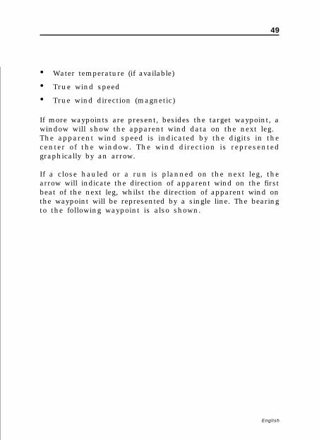
• Water temperature (if available)
• True wind speed
• True wind direction (magnetic)
If more waypoints are present, besides the target waypoint, awindow will show the apparent wind data on the next leg.The apparent wind speed is indicated by the digits in thecenter of the window. The wind direction is representedgraphically by an arrow.
If a close hauled or a run is planned on the next leg, thearrow will indicate the direction of apparent wind on the firstbeat of the next leg, whilst the direction of apparent wind onthe waypoint will be represented by a single line. The bearingto the following waypoint is also shown.

50
English
NAVIGATION WINDOWS
These windows are automatically enabled as soon as the GPSreceiver has obtained a valid fix (FIX OK).If no route has been entered, the following data will be shown:
• Boat’s speed
• Chart scale
• Course
• Sea depth (if available)
• Water temperature (if available)
• Local time
To change the chart scale, press the -ZOOM+ key.
Navigation Windows

51
English
If a route has been entered, the Navigation window will showthe following data:
• Boat’s speed
• Chart scale
• Target waypoint
• Distance to the target waypoint
• Time to arrive to the target waypoint
• Estimated time to the route end
• Sea depth (if available)
• Water temperature (if available)
NOTE: To display sea depth and temperature values, the GEONAV must be inter-faced with a depth sounder.
52
English
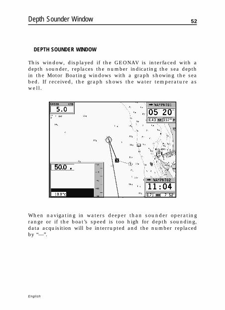
DEPTH SOUNDER WINDOW
This window, displayed if the GEONAV is interfaced with adepth sounder, replaces the number indicating the sea depthin the Motor Boating windows with a graph showing the seabed. If received, the graph shows the water temperature aswell.
When navigating in waters deeper than sounder operatingrange or if the boat’s speed is too high for depth sounding,data acquisition will be interrupted and the number replacedby “—”.
Depth Sounder Window

53
English
2D/2D SPLIT WINDOWS
The 2D/2D split windows allow displaying, at the same time,two different areas on the chart. For instance you can seeyour ship’s position at two different zoom levels in the twowindows. Or, while you insert a route in one window, youcan keep under control your ship’s position in the other one.To activate the 2D/2D split windows press GOTO to displaythe menu, select SETUP, 2D/2D SPLIT WINDOWS and editthe option as desired.
After enabling this option, the two windows can be shown bypressing repeatedly the EXIT key. The two windows, the leftone and the right one, can be operated independently. Theusual operations (zoom, pan, waypoint and marker insertion,etc.) are available in the active window, i.e. the one markedby a surrounding frame.
2D/2D Split Windows

54
English
To change the active window from left to right or vice versa,hold EXIT pressed for a short time. Note that if a window is inCursor mode, because the cursor has been moved, pressingEXIT returns in Navigation mode, without changing the activewindow. Press EXIT again to change the active window.
To exit from the 2D/2D split windows, hold the EXIT keypressed for a few seconds.
2D/2D Split Windows

55
English
2D/3D SPLIT WINDOWS
NOTE: This function is available only with the NAVIONICS Platinum™ cartridges.
The 2D/3D split windows allow displaying, at the same time,standard cartography (2D) and three-dimensional cartogra-phy (3D); this requires a Navionics Platinum™ chart.
To activate the 2D/3D split windows press GOTO to displaythe menu, select SETUP, 2D/3D SPLIT WINDOWS and editthe option as desired.
After enabling this option, the two windows can be shown bypressing repeatedly the EXIT key. The two windows, the leftone and the right one, can be operated independently.
When the 2D window is active, i.e. marked by a surroundingframe, the usual plotter operations (zoom, pan, waypoint andmarker insertion, etc.) are available.
2D/3D Split Windows

56
English
To change the active window from 2D to 3D or vice versa,hold EXIT pressed for a short time. When the 3D window isactive, use the joystick to displace the view point, the ZOOMkey to enlarge or reduce the image and the knob to rotate theview.
The knob allows also to raise the view point and to change itsangle. Press the knob to switch from one function to another.After changing the point of view, using either the joystick orthe knob, it is possible to restore the original point of view bypressing EXIT.
To exit from the 2D/3D split windows, press EXIT and hold itpressed for a few seconds.
2D/3D Split Windows

57
English
TRIP WINDOW
The Trip window shows general data relating to the routefollowed:
• Average speed from departure
• Maximum speed from departure
• Time elapsed from departure
• Partial distance covered from departure
• Overall distance covered
To reset all counters (except for the overall distance) beforestarting a new journey, press the CLR key.
Trip Window

58
English
SATELLITE WINDOW
At start-up the satellite window displays how many and whichsatellites are tracked by the GPS receiver.The outer circle represents the horizon, the inner one identi-fies a 45° elevation with respect to the horizon, and the cen-tral circle points to the zenith.
The small squares with numbers show the satellites avail-able. As soon as a satellite is tracked by the GPS receiver, thenumber inside the square is displayed in reverse.
The bars displayed on the left identify the signal quality; thelonger the bar, the higher the signal quality.On the left of each bar, two digits indicate the signal/noiseratio.
Satellite Window

59
English
Additional information:
• Day, month, year, local or Greenwich time (at the firststart-up the GEONAV is initialized to Greenwich Time).
• Boat’s position (lat/lon) (or the latest valid fix if the GPSreceiver is still searching for satellites).
• Data on the current satellite situation (number and fix).
• SOG, COG and altitude.
The latitude and longitude values relevant to the boat’s posi-tion are displayed as soon as three satellites are tracked and a2D fix (two dimensions) is available.The altitude value is available only if four satellites are trackedand a 3D fix is obtained.
As soon as a valid fix is available, the GEONAV will automati-cally switch to Navigation mode and display the boat’s posi-tion at the best chart range available; the window at the bot-tom of the screen will indicate the boat’s course and speed.
To recall the Satellite window, press the EXIT key repeatedlyuntil it appears.

60
English
GENERAL INFO WINDOW
This window displays the following information on the boat’scurrent position:
• Geographical coordinates (latitude/longitude)
• The position correction applied to the latitude and longi-
tude (SETUP, CALIBRATION)
• Magnetic variation value received by the GPS
• Course (COG)
• Speed (SOG)
NOTE: This window is available in Navigation mode only.
General Info Window

61
English
TIDE INFO WINDOW
When a NAVIONICS cartridge featuring Tides and Currentsdata is present, this window displays further information,besides the forecast data supplied by selecting the Tides andCurrents station.The following data is displayed:
• Latitude and longitude at the
current boat’s position
• Current time and date
• Value of magnetic variation
received by the GPS
• Dawn and sunset time
• Moonrise and moonset time
• Moon phase
• Graph of estimated tide level
with respect to the current
position
WARNING: Unlike the graph displayed at a T&C station position (accessible throughthe GOTO function, or by positioning the cursor on the Tides and Currents stationsymbol) that is accurate since it is supplied by hydrographic offices, this graphshows estimated data, being the result of interpolation between the two Tides andCurrents stations nearest to the point of interest. The accuracy of the estimate mayvary, depending on the coast type, the distance to the nearest stations, and othergeographical features.
Tide Info Window

62
English
RUNWAY WINDOW
This window displays the fol-lowing information on the tar-get waypoint:
• Name of the target waypoint
• Distance from the target
waypoint
• Estimated time of arrival to
the target waypoint
• Bearing
• Course
• Steering angle
• XTD (right/left distance
from the planned route)
• XTD limit (runway width)
The graph shows the boat’s position with respect to the route.When the XTD reaches the extreme value shown in the lowerright-hand corner of the window, the boat symbol will reachthe runway right or left side.To change the XTD limit, see the Setup Section.
NOTE: This window is available in Navigation mode only.
Runway Window

63
English
MAIN MENU
The main menu bar, that appears when pressing the GOTOkey, allows accessing the following options:
ROUTE: To display route information, reverse and delete theroute, set the consumption data and save or read data from thecartridge.
TRACK: To enable/disable the track function, delete a track,choose the track color, show the used percentage of trackmemory and save or read data from the cartridge.
MARKER: To delete markers, choose the marker color, showthe number of markers used and available, and save or readmarker data from the cartridge.
GOTO PORT: To plan a route to a selected port.
GOTO NEAREST: To plan a route to the nearest port service.
SETUP: To enable/disable and change the plotter’s setup.
GOTO LAT/LON: To plan a route to a known geographical posi-tion.
GOTO RANGE/BEARING: To plan a route to a position whose rangeand bearing values are known.
NOTE: The majority of menu items, once selected, show a series of submenus. Usethe joystick to move from one menu to another and press ENTER to choose one item.
Main Menu

64
English
ROUTE
EDITING A ROUTE (CURSOR MODE)Creating a waypointUsing the joystick, move the cursor on the position desiredand press ENTER to insert a waypoint.To enter further waypoints, move the cursor and press ENTER.The new waypoint will be appended to the existing route.
Up to 99 waypoints per route can be entered, also by using theGOTO functions available from the main menu.
Deleting the last waypointPress CLR. If the last waypoint is out of screen, the “DELETEWP? ENTER = YES” message will be displayed.Press ENTER to confirm the deletion.
Deleting a waypointUse the joystick to position the cursor on the waypoint todelete and press the CLR key.
Deleting all waypoints in a routePress the CLR key repeatedly until the “NO WP PRESENT”message is displayed.
Moving a waypointPosition the cursor exactly on the waypoint to be moved; pressENTER to capture the waypoint, then move the waypoint to theposition desired and confirm the operation by pressing ENTER.
Inserting a new waypoint in a routePosition the cursor exactly on the route leg to edit and pressENTER to capture the leg. Once captured, the leg will show athicker line to distinguish it more easily from the other routelegs. A window will also show the leg captured and its length.Move the manual cursor to the position desired, insert thenew waypoint and confirm by pressing ENTER.
Route

65
English
EDITING A ROUTE (NAVIGATION MODE)If the manual cursor is displayed, press the EXIT key to enterNavigation mode.
Changing the target waypointUse the “Route to a waypoint” function (see the Functions inthe Route Menu Section).
WARNING: The route will be modified and the new target waypoint selected will bethe first waypoint in the route.
Deleting all waypointsPress the CLR key to show the “DELETE ROUTE? ENTER =YES” message. Press the ENTER key to confirm the deletion oranother key to exit.
FUNCTIONS IN THE ROUTE MENURoute InfoRoute information is displayed on several adjacent pages con-taining general route information and the geographical coor-dinates of all waypoints. Press GOTO to display the main menu,then select ROUTE, CURRENT and GOTO WP. A windowwill show the following information:
WP NAME : Waypoint name
DISTANCE: Distance from START to current waypoint
TIME: Estimated time from START to current waypoint
FUEL LITERS: Estimated fuel consumption (liters or gallons)
BRG: Bearing from previous waypoint to current waypoint
POSITION: Waypoint latitude / longitude

66
English
Route
The arrival time at the waypoint and the fuel consumptionwill be displayed provided that estimated speed and fuel con-sumption values have been inserted previously (see the Enter-ing speed and fuel consumption data Section).
To move within the page and scroll the adjacent pages, usethe joystick. To go back to the menu, use the joystick; to exit,press the EXIT key.
Entering speed and fuel consumption dataThe data are used to calculate the values displayed in theROUTE window.Press the GOTO key to display the menu, select ROUTE, CUR-RENT, SET SPEED and press ENTER. Use the joystick to enterthe data required and to confirm the operation.
Storing a route in the CompactFlash™Press the GOTO key to display the menu, select ROUTE, CUR-RENT, SAVE and press ENTER. To change the default name,use the joystick. To confirm the operation, press ENTER.
67
English
A message will confirm that the route has been stored cor-rectly. Once stored, the route will disappear from the screen.
Recalling a route from the CompactFlash™Press the GOTO key to display the menu, select ROUTE, OLDand press ENTER to open the route catalog; select the route bythe joystick and then press ENTER to confirm, or EXIT to exit.The route recalled will be displayed, the Autozoom functionautomatically enabled and a window will allow selecting thetarget waypoint.
Deleting a routeTo delete the route displayed, press the GOTO key to show themenu, select ROUTE, CURRENT, DELETE and press ENTER toconfirm.To delete a route stored in the CompactFlash™, press the GOTOkey to show the menu, then select ROUTE and OLD.Select the route from the list of the routes stored in theCompactFlash™, then press CLR to delete it and ENTER to con-firm the operation.
Reversing a routePress the GOTO key to display the menu, select ROUTE, CUR-RENT and then REVERSE.The waypoint order will be automatically reversed allowingnavigation in the opposite direction.
Route to a waypointPress the GOTO key, select ROUTE, CURRENT, GOTO WP andmove the cursor within the waypoint list by using the joy-stick. Press ENTER and select the target waypoint by the joy-stick. Press ENTER to confirm the selection, or EXIT to exit.
As the GEONAV plots a new route, the waypoint selected be-comes the first waypoint in the route, whereas previouswaypoints are deleted.

68
English
TRACK
The Track function allows recording the track actually fol-lowed by the boat. The Track function can be enabled anddisabled several times during navigation; in this case, sepa-rate track segments will be drawn.
Starting a trackTo enable the Track function, press the GOTO key to displaythe main menu, select TRACK, START and press ENTER toconfirm. A small circle on the boat’s position will indicate thetrack starting point.
Stopping a trackTo disable the Track function, press the GOTO key to displaythe main menu, select TRACK, STOP and press ENTER to con-firm.
Storing a track in the CompactFlash™Press the GOTO key to display the main menu, select TRACK,
Track

69
English
CURRENT, SAVE ALL and press ENTER to confirm. To changethe default file name, use the joystick. To confirm the opera-tion, press ENTER.
A message will confirm that the track has been stored cor-rectly. Once stored, the track will disappear from the screen.Each time a track is stored in the CompactFlash™, the plotter’smemory is cleared and the indicator of memory used in theTRACK menu is reset to 0%.
Recalling a track from the CompactFlash™Press the GOTO key to display the main menu, select TRACK,OLD and press ENTER to open the track catalog.Select the track desired, then press ENTER to confirm the op-eration or EXIT to exit.
Deleting a trackTo delete the track displayed, press the GOTO key to show themain menu, select TRACK, CURRENT, DELETE ALL and pressENTER to confirm.
To delete a track stored in the CompactFlash™, press the GOTOkey to show the menu, then select TRACK and OLD.Select the track from the list of the tracks stored in theCompactFlash™ , then press CLR to delete it and ENTER to con-firm the operation.
Setting the track colorThe track color can be selected from the menu; press the GOTOkey to display the main menu, select TRACK, CURRENT,COLOR, choose a color by the joystick and confirm the selec-tion by pressing ENTER. The selected color will be stored to-gether with the track.
NOTE: The track color cannot be changed while the recording is active.
70
English
Displaying and changing track segment dataPosition the manual cursor on a point in the track segment.A window will show the navigation data recorded in that po-sition.
• Recording date
• Recording time
• Sea depth
• Water temperature
• True wind direction
• True wind speed
Wind and depth values are displayed only if available.
By positioning the manual cursor on the starting point of atrack segment, a menu will allow changing the segment name,displaying average/maximum speed data, trip length/time, de-leting the single segment as well as changing the single seg-ment color.
When the menu pops up, press ENTER to access the options,then use the joystick to select the desired option and pressENTER to confirm.
Route to a track segmentPress the GOTO key and select TRACK, CURRENT, GOTOTRACK by the joystick. A window will show, for each tracksegment, the line color, the name, the recording start dateand time as well as the recording duration and length.
The list can be sorted by using the joystick to select the sortfield and ENTER to confirm. Use the joystick to select the targetsegment (the latest 8 segments used will be highlighted) fromthe catalog and then press ENTER to confirm.
Track

71
English
The GEONAV will position the manual cursor at the begin-ning of the track segment selected; insert a waypoint by press-ing ENTER, or a marker by holding ENTER pressed.
Setting the track densityPress the GOTO key and select TRACK, CURRENT, TRACKDENSITY by the joystick. A window will allow setting thetrackpoint saving density by time interval, distance or auto-matically.
Automatic trackWhen no track has been manually enabled by the user, theAutomatic track function will allow keeping the record of theroute anyway.The automatic track is active provided that no track has beenpreviously set by the user and is displayed in a different colorso as to distinguish it from the user’s track.
To save the automatic track, press GOTO, select TRACK, CUR-RENT and SAVE ALL. To change the default file name, usethe joystick.
NOTE: The symbol identifying the track starting point will not be shown in case ofautomatic track.
72
English
MARKERS
Markers are used to identify points of interest to which namesand symbols can be assigned.
When a marker is entered, the plotter records also date, timeand sea depth and temperature (if available). This data is storedtogether with the marker name, symbol and color and can bedisplayed in the window shown by the GOTO MARKER menu.
NOTE: Marker names are displayed starting from the 32 NM chart scale.
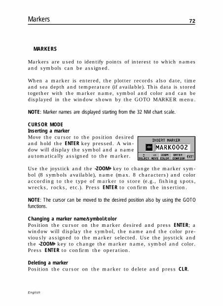
CURSOR MODEInserting a markerMove the cursor to the position desiredand hold the ENTER key pressed. A win-dow will display the symbol and a nameautomatically assigned to the marker.
Use the joystick and the -ZOOM+ key to change the marker sym-bol (8 symbols available), name (max. 8 characters) and coloraccording to the type of marker to store (e.g., fishing spots,wrecks, rocks, etc.). Press ENTER to confirm the insertion.
NOTE: The cursor can be moved to the desired position also by using the GOTOfunctions.
Changing a marker name/symbol/colorPosition the cursor on the marker desired and press ENTER; awindow will display the symbol, the name and the color pre-viously assigned to the marker selected. Use the joystick andthe -ZOOM+ key to change the marker name, symbol and color.Press ENTER to confirm the operation.
Deleting a markerPosition the cursor on the marker to delete and press CLR.
Markers

73
English
NAVIGATION MODEInserting a markerHold the ENTER key pressed to insert a marker at the boat’sposition. A window will display the symbol and the nameautomatically assigned to the marker; to change the markersymbol, name and color according to the type of marker tostore (e.g., fishing spots, submerged wrecks, rocks, etc.), usethe joystick and the -ZOOM+ key. Press ENTER to confirm theinsertion.
Route to a markerPress the GOTO key and select MARKER, CURRENT, GOTOMARKER by the joystick. The catalog displayed will list, withrespect to each marker, the symbol, the name, the insertiondate/time, as well as, if available, the sea depth and tempera-ture values as detected when entered.
Moreover, the catalog shows the number of markers enteredin the current page and the number of markers still available.The list can be sorted by using the joystick to select the sortfield and ENTER to confirm.

74
English
By using the joystick, choose the desired marker (the latest 8markers used will be highlighted) from the catalog displayed,then press ENTER to confirm.
Once the desired marker has been selected, the GEONAV willinsert a waypoint at the marker position and append the newleg to the existing route (if no route is available, the newwaypoint will be connected to the boat’s position).Press the EXIT key to go back to Navigation mode and enableautomatically the Autozoom function.
NOTE: To delete a single marker, select it from the GOTO Marker list and press theCLR key.
FUNCTIONS IN THE MARKER MENUStoring a set of markers in the CompactFlash™Press the GOTO key to display the menu, select MARKER, CUR-RENT, SAVE ALL and press ENTER. Use the joystick to changethe default name and press ENTER to confirm the operation.
A message will confirm that markers have been stored cor-rectly. Once stored, markers will disappear from the screen.Each time a set of markers is stored in the CompactFlash™,the plotter memory is cleared and the indicator of the markersavailable is reset to the maximum value.
Recalling a set of markers from the CompactFlash™Press the GOTO key to display the menu, select MARKER, OLDand press ENTER to open the marker catalog.Select the marker set desired by using the joystick, then pressENTER to confirm the operation, or EXIT to exit.
Deleting markersTo delete the set of markers displayed, press the GOTO key toshow the menu, select MARKER, CURRENT, DELETE ALLand press ENTER to confirm.
Markers

75
English
To delete a single marker among those displayed, press theGOTO key to show the menu, select MARKER, CURRENT andGOTO MARKER. Select the marker desired from the list shown,then press CLR to delete it and ENTER to confirm the operation.
To delete a set of markers stored in the CompactFlash™, pressthe GOTO key to show the menu, then select MARKER andOLD.By using the joystick, select the set of markers from the list ofthose stored in the CompactFlash™, then press CLR to deleteit and ENTER to confirm the operation.

76
English
GOTO PORT
Press the GOTO key and select PORT by the joystick.
The list will display the latest ten ports previously selected.Choose the desired port by the joystick, or select New to dis-play the whole list of the ports stored in the cartridge.
By moving the joystick in the four directions, form the portname, or part of it; when the desired port is shown, highlightit by the joystick and confirm its selection by pressing ENTER.
Once the desired port has been selected, the GEONAV willinsert a waypoint in the port position and append the new legto the existing route (if no route is available, the new waypointwill be connected to the boat’s position).Press the EXIT key to go back to Navigation mode and enableautomatically the Autozoom function.
Goto Port

77
English

78
English
GOTO NEAREST
NOTE: This option is available only with the NAVIONICS cartridges containing thePort Services features. It allows finding and heading for the nearest port featuring theservice desired. The NAVIONICS Platinum™ cartridges offer a wide choice of ser-vices, whereas, when using NAVIONICS Gold™ cartridges, the functions supportedwill be those provided by plotters employing Gold™ charts only.
Press the GOTO key, select NEAREST by the joystick, choosethe desired service and press ENTER to confirm, or EXIT to can-cel the operation.
The GEONAV will show the three destinations closest to theboat’s position (if in Navigation mode), or to the cursor’s posi-tion (if in Cursor mode), and position automatically on theclosest destination (flashing).
Select one port at a time by using the joystick; a window willshow the distance and time to arrive (estimated on the boat’scurrent speed). Press ENTER to confirm the selection.
Goto Nearest

79
English
The GEONAV will insert a waypoint in the port selected, de-lete automatically the existing route (if in Navigation mode), orappend the waypoint to the existing route (if in Cursor mode),then go back to Navigation mode and enable automatically theAutozoom function.
Besides the specific set of services shown in the figure, ageneric set is available. It gathers several additional services(such as hotels, restaurants, airports, shops, etc.) that can besearched for and located thanks to the Nearest function.
Tide or current forecast at the nearest survey station
NOTE: This function is available only with the NAVIONICS cartridges containingTides and Currents data.
This function allows displaying, within the space of twenty-four hours with respect to the selected date, the tide level andtidal current speed and direction at a survey station in thevicinity. Unlike the estimated data shown in the Info win-dow, this forecast is much more accurate, being supplied di-rectly by tidal surveying stations.
Press the GOTO key, select NEAREST by the joystick, choosethe Tides or Currents service, then press ENTER to confirm.The GEONAV will allow selecting one of the three nearestTides and Currents stations. Use the joystick to choose thestation desired, then press ENTER to confirm. A window willshow the information reported below.
Tide station• Name of the station
• Forecast reference date
• Time and height with respect to the cursor’s position in
the graph
• Time and height of high/low water

80
English
Goto Nearest
• Dawn and sunset time
• Moonrise and moonset time
• Moon phase
• Tide level graph (24 hours)
Tidal current station• Name of the station
• Forecast reference date
• Time, speed and direction with respect to the cursor’s po-
sition in the graph
• Time, speed, direction and slack time of daily flood and
ebb streams
• Dawn and sunset time
• Moonrise and moonset time
• Moon phase
• Tide level graph (24 hours)

81
English
In both cases above, the default date is today. A different datecan be set by pressing ENTER or -ZOOM+.
NOTE: The same information can be accessed by positioning the manual cursor onthe icon of a Tides or Currents station, and pressing ENTER to confirm.

82
English
SETUP
The Setup menu allows setting the available options. To ac-cess the Setup menu, press GOTO to display the main menu,then select SETUP by using the joystick.
The menu items are grouped in seven sets. When selecting aset by the joystick, the list of the available options will bedisplayed. Press ENTER to select one set, then use the joystickto switch from one option to another and edit the setting. Togo back to the set list, press EXIT.
DISPLAY• Mode (BRIGHT/DAY/NIGHT)
Selects the colors suitable for the environment.• Safety Depth (OFF/2m/5m/10m/20m)
Enables the display of theareas corresponding to thedepth safety contour.
• Depth Contours (ALL/5m/10m/20m)Selects the display of depthcontours.
• Photo Overlay (LAND/FULL/OFF)Selects the enabling of the overlay of satellite photographsfor charts: only on land, everywhere or off, respectively.
• Chart Rotation (ON/OFF)Enables/disables the Chart Rotation function.
• Set Chart Detail (ON/OFF)By selecting ON, the chart details to display (STD/USR/ALL) can be chosen. It is possible to select one of the twosettings available (STD - equivalent to the standard displaysetting, as defined by ECS regulations - and ALL, that en-ables the display of all the items on the chart), or, by choos-ing USER, enable/disable the display of the single items.
Setup

83
English
• Easy View (ON/OFF)Enables/disables the Chart Magnification function.
• Overzoom (ON/OFF)Enables/disables the Overzoom function.
• Presentation (INTER./U.S.)Selects the symbols and colors of chart presentation.
• Own Ship IconSelects the icon that will identify the ship’s position onthe screen.
3D DISPLAY• Photo (ON/OFF)
Selects the type of texture forthe 3D display, to choose fromsatellite photograph andsimple texture.
NAVIGATION• Route Plan (GREAT C./RHUMB L.)
Selects the Route Planning mode between Great Circle orRhumb line.
• XTD Alarm (ON/OFF)Sets the maximum deviation allowed from the route set.
• Calibration (ON/OFF)Calibrates the ship’s position received by the GPS.
• Anchor Alarm (OFF/15m/30m/50m)Enables/disables the alarmand sets the distance rangefor the anchor alarm.
UNITS AND LANGUAGE• Set Time (LOCAL/GMT)
Enters local time.• Distance Units (NAUT/METR/STAT)
Selects distance units.

84
English
Setup
• Depth Units (M/FT/FA)Selects depth units.
• Bearings (TRUE/MAG)Sets the magnetic mode for all bearings.
• Language (EN/FR/ES/DE/DK/IT/SV/NL/SU/NO/GR)Selects the language.
WINDOWS• Selects the auxiliary windows to dis-
play. For every window, a previewimage - whose display can be en-abled/disabled (ON/OFF) - is avail-able.
ARPA• Activate ARPA (ON/OFF)
Enables/disables the display of ARPA targets.• Set CPA/TCPA Limits (ON/OFF)
Sets the limits for CPA (Closest Point of Approach) and TCPA(Time to Closest Point of Approach)alarms.
• Offset GPS Radar (ON/OFF)Sets the offset between the GPS unitand the radar antenna.
OTHER• Chart Info
By selecting ON, a window willshow the catalog of the charts storedin the cartridge.Select one chart by the joystick andpress ENTER to display the information associated, or EXIT toexit.
• Welcome Message (ON/OFF)Enables/disables the display of a message in the welcomepage, appearing as the instrument is turned on.By selecting ON, a window will allow writing or editingthe message.

85
English
86
English
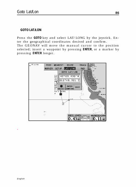
GOTO LAT/LON
Press the GOTO key and select LAT/LONG by the joystick. En-ter the geographical coordinates desired and confirm.The GEONAV will move the manual cursor to the positionselected; insert a waypoint by pressing ENTER, or a marker bypressing ENTER longer.
.
Goto Lat/Lon

87
English
GOTO RANGE/BEARING
Press the GOTO key and select R&B by the joystick. Enter therange and bearing values relative to the position desired andconfirm.The GEONAV will move the manual cursor to the positionselected; insert a waypoint by pressing ENTER, or a marker byholding ENTER pressed.
Goto Range/Bearing

88
English
MOB FUNCTION
If one member of the crew should accidentally fall overboard,the MOB (Man Overboard) function allows plotting the posi-tion where the fall occurred, providing useful pieces of infor-mation for the rescue.
To enable the MOB function, hold the GOTO key pressed longer.The GEONAV will place a special marker on the current posi-tion and show a window with the following data:
• Geographical coordinates of the man overboard position
• Time elapsed from the fall
• Distance and bearing of the man overboard with respect to
the boat’s subsequent positions
If the unit is connected to an autopilot, the transmission ofcommands to the autopilot is stopped.All the unit’s functions are disabled as long as the MOB func-tion is active. It will be only possible to zoom in / out thechart.
To disable the MOB function and go back to the standard func-tions, press EXIT.
MOB Function

89
English
ETHERNET CONNECTION
The GEONAV features Ethernet Connection, a system for thenetwork connection (Ethernet) of several plotters. This sys-tem makes it possible to transfer the changes to a route - in-cluding temporary changes made through the Easy Pilot func-tion - from one plotter to another.Another innovative feature is the sharing of the electronicchart among several instruments, without having to purchasemore than one original chart to be used on one GEONAV; allthe other instruments connected to the network can use cop-ies of the original chart (see Chart sharing).
NOTE: No GPS receiver suitable for network connection to the Ethernet Connectionhas been put on sale yet. Therefore, it is necessary to connect each plotter to a GPSreceiver by the NMEA0183 standard port. In any case, a single GPS receiver can beconnected to several plotters. The autopilot, however, must be connected to only oneof the plotters on the network, still using the NMEA0183 standard port.
Connecting the instrumentsThe installation of the Ethernet Connection system, to be car-ried out only by skilled personnel, requires the use of stan-dard Ethernet cables and connectors (UTP cat. 5 cables andRJ-45 connectors). To connect to the network more than twoinstruments, use one cable (Code no. N1016140) for each plot-ter and connect one another by a network hub available on themarket. To execute a link between two instruments only, usethe Ethernet kit (Code no. P201086) including two networkcables, two adapters and one crossover 10 meters long.
Once the network has been appropriately implemented andset as described in the following paragraph, the Ethernet Con-nection system will be automatically detected at start-up andthe instruments made ready for data transfer.
Setting the networkTo ensure a correct network communication, the plotters have
Ethernet Connection

90
English
Ethernet Connection
to be assigned network addresses different from those assignedto any external device (PC, printer, server, etc.) connected tothe same network.
The setting of network parameters is automatic. To solve pos-sible conflicts that cannot be handled automatically, this op-eration can also be carried out manually. Press GOTO to displaythe main menu, select SETUP, OTHER and then press theGOTO and ENTER keys simultaneously.
Transferring the routeThe operations that allow editing an active route - and thatare therefore transferable to all the instruments on the net-work - are the following:
- Route editing (insertion, deletion and displacement of awaypoint; recall and deletion of a route)
- Insertion of a waypoint and selection of the target waypointby the GOTO function
- Temporary editing of the route by the Easy Pilot function(EBL knob)
As one of the above operations has been carried out from anyinstrument connected to the network, switch from Cursor modeto Navigation mode by pressing the EXIT key.

91
English
The route edited will be transferred to all the instrumentsconnected to the network, thus overwriting the local routedata (if any). To cancel the route transfer operation, press CLR.
NOTE: After canceling the transfer of the edited route, it is still possible to save thechanges to the cartridge inside the instrument; press ENTER to confirm the saving orCLR to cancel. In both cases, as the operation has been completed, the instrumentrestores the original active route. The route saved to the local cartridge can berecalled later and then transferred to the network.
Chart sharingUsually the plotter can read the electronic chart exclusivelyfrom the CompactFlash™ cartridge to which it was saved atthe moment of purchase. Now, thanks to the Chart Sharingfunction, that allows copying the electronic chart to as manyCompactFlash™ cartridges as the instruments connected tothe network, all the plotters will be able to read them: it isrequired just to insert the original CompactFlash™ cartridgeinto any instrument.
To make a copy of the charts, a PC equipped with aCompactFlash™ reader is required. Access the original car-tridge by the MS-Windows File Manager, copy the\NAVIONIC\CHARTS folder to a temporary location in the harddisk, then insert a new CompactFlash™ into the reader andcopy the content of the \NAVIONIC\CHARTS folder from thehard disk to the \NAVIONIC\CHARTS folder in theCompactFlash™. If necessary, create the \NAVIONIC\CHARTSfolder in the new CompactFlash™ by the File Manager.
Be careful not to delete the chart files already present in thetarget CompactFlash™ (if any). Repeat the operation for as manyCompactFlash™ cartridges as necessary to fit all the plotterson the network.
NOTE: The Chart Sharing function is active provided that the instrument with theoriginal CompactFlash™ is connected to the network and turned on.

92
English
AUTOPILOT
The GEONAV allows a boat equipped with an autopilot to fol-low automatically the entered route, compensating for any di-version caused by external conditions (wind, currents, etc.).
The GEONAV will display the “PROXIMITY TO WAYPOINT”message to warn the user that the boat is about to reach thetarget waypoint.
The GEONAV will display the “END OF TRIP” message towarn the user that the boat is about to reach the last waypointin the route.
WARNING: In order to avoid sudden change of course, it is always recommendedto disable the autopilot when editing and/or creating a route.
Autopilot

93
English
Table of Contents
TABLE OF CONTENTSINTRODUCTION ............................................................................................ 4CHARACTERISTICS ...................................................................................... 5INSTALLATION AND PRECAUTIONS .......................................................... 8CONNECTIONS .......................................................................................... 11CARTRIDGE INSTALLATION ....................................................................... 13KEYBOARD .................................................................................................. 15DIAGNOSTIC ................................................................................................ 18NAVIONICS ELECTRONIC CHARTS ........................................................ 19GRAPHIC ITEMS ......................................................................................... 28FUNCTIONAL CHARACTERISTICS .......................................................... 30QUICK TOUR ............................................................................................... 41OPERATING MODES .................................................................................. 44RANGE WINDOW ........................................................................................ 47SAILING WINDOWS .................................................................................... 48NAVIGATION WINDOWS ............................................................................. 50DEPTH SOUNDER WINDOW ..................................................................... 522D/2D SPLIT WINDOWS .............................................................................. 532D/3D SPLIT WINDOWS .............................................................................. 55TRIP WINDOW ............................................................................................. 57SATELLITE WINDOW .................................................................................... 58GENERAL INFO WINDOW .......................................................................... 60TIDE INFO WINDOW .................................................................................... 61RUNWAY WINDOW ..................................................................................... 62MAIN MENU ................................................................................................ 63ROUTE .......................................................................................................... 64TRACK ........................................................................................................... 68MARKERS .................................................................................................... 72GOTO PORT ................................................................................................. 76GOTO NEAREST .......................................................................................... 78SETUP ........................................................................................................... 82GOTO LAT/LON ............................................................................................. 86GOTO RANGE/BEARING ........................................................................... 87MOB FUNCTION ......................................................................................... 88ETHERNET CONNECTION ........................................................................ 89AUTOPILOT ................................................................................................... 92