Embed Size (px)
Citation preview

G 364: Mobile and Wireless NetworkingCLASS 21, Mon. Mar. 29 2004Stefano BasagniSpring 2004M-W, 11:40am-1:20pm, 109 Rob
3/29/04 2
Global System for Mobile Communications (GSM)
Digital wireless network standard designed in Europe
Provide a common set of compatible services and capabilities
User throughout Europe and more
Several millions of customers worldwide
3/29/04 3
Basic Requirements
Services
Quality of Service (QoS) and security
Radio frequency utilization
Network
Cost

3/29/04 4
Services
Service portability: MSs can be used in all participating countries Services like in the wireline network, as well as mobile-specific servicesService is provided to vehicle-mounted MSs, as well as to those used by pedestrian or on a ship

3/29/04 5
QoS and Security
GSM quality of voice services has to be as least as good as the one of previous analog systemsInformation encryption is provided to those who require itCost is kept low enough not to affect users that do not require it

3/29/04 6
Radio Frequency Utilization
High level of spectrum efficiency and state-of-the-art subscriber facilities
Operating in the entire allocated frequency band
Coexist with earlier systems in the same frequency

3/29/04 7
Network and Cost
Identification and numbering plan based on ITU recommendationsStandard signaling system for switching and mobility managementPublic network should not be significantly affectedDesign to limit the cost of the complete system, in particular the MSs

3/29/04 8
GSM Architecture
Mobile Station (MS), communicate withBase Station System (BSS), via theRadio InterfaceBSS is connected to the Network and Switching Subsystem (NSS) via aMobile Switching Center (MSC) usingA interface

3/29/04 9
Mobile Station
Consist of two partsSubscriber Identity Module (SIM)Mobile Equipment (ME)
Broader definitionTerminal Equipment (TE): PDA or PC connected to the METhe SIM + ME are called the Mobile Terminal
3/29/04 10
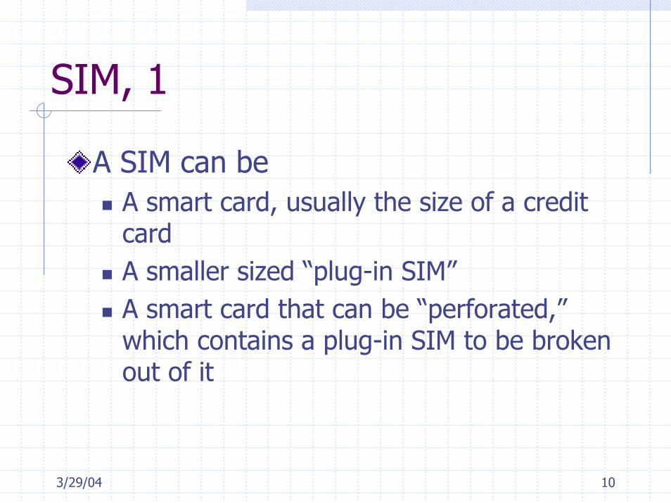
SIM, 1
A SIM can beA smart card, usually the size of a credit cardA smaller sized “plug-in SIM”A smart card that can be “perforated,” which contains a plug-in SIM to be broken out of it

3/29/04 11
SIM, 2
A SIM is protected by a Personal Identity Number (PIN), between 4 to 8 digits in lengthPIN is loaded on the SIM by the network operator at subscription timeCan be activated or changed by the userProtected by the PIN Unblocking Key (PUK)

3/29/04 12
SIM, 3
A SIM contains subscriber-related information (+ PIN + PUK)Include: Short list of abbreviated and customized short dialing numbersShort messages received when the user is not presentName of preferred networks to provide serviceRS232 modifiable (or via MS keypad)“SIM toolkit”

3/29/04 13
Mobile Equipment (ME), 1
The ME contains non-customer related hardware and software specific to the radio interface
It cannot be used to reach the service without SIM, except for emergency calls
A SIM can fit several MEs

3/29/04 14
ME, 2
At every connection, SIM sends to the network the classmark of its current METhis SIM-ME design enhances portability and securityThe ME is property of the userThe SIM is loaned to the subscriber, but it is owned by the service provider

3/29/04 15
ME Max Power: 5 Power Classes
portable0.8V
portable2IV
portable5III
vehicular8II
vehicular20I
Type of terminal
max power (watt)CLASS
Normally used
This was for 900 MHz – for 1800 MHz only two classes: 1W, and 0.25 W

3/29/04 16
Base Station System (BSS)
Connects the MSs to the Network Switching Subsystem (NSS)Consist of two parts:
The Base Transceiver Station(BTS)The Base Station Controller (BSC)

3/29/04 17
Base Transceiver Station
The BTS containsTransmitterReceiver Signaling equipment specific to the radio interface Transcoder/Rate Adapter Unit (TRAU): Implements GSM-specific encoding-decoding and rate adaptation in data transmission

3/29/04 18
TRAU possible placements
BTS TRAU BSC MSC
64 kbit/s64 kbit/sOn BTS 13 kbit/s
BSC TRAU
13 kbit/s
On BSC
64 kbit/s16 kbit/sMSCBTS
13 kbit/s
On MSC64 kbit/s
(4x16 sub-mux)
BTS BSC
16 kbit/sMSCTRAU
Why 16 kbps instead of 13? Inband signalling needed for BTS control of TRAU(TRAU needs to receive synchro & decoding information from BTS)

3/29/04 19
Base Station Controller
The BSC:Support radio channel allocation/releaseHandoff management
May connect to several BTSs (not in GSM) and maintain their cell configuration dataCommunicated to the BTS via ISDN protocols using the A-bis interfaceIn GSM BTS and BSC are usually co-located and integrated (do not need the A-bis interface)

3/29/04 20
BSC, Capacity Planning
Busy hours processor load allocation:Call activities: 20/25%Paging and SMSs: 10/15%Mobility management (handoff and location update): 20/25%Hardware checking/Network-triggered events: 15/20%
Overload rejects: 1) location update, 2) MS originating calls, 3) handoffs

3/29/04 21
GSM system hierarchy
BTS
BSCLOCATION AREA
MSC
MSC region
MSC: Mobile Switching CenterLA: Location AreaBSC: Base Station ControllerBTS: Base Transceiver Station
Hierarchy: MSC region n x Location Areas m x BSC k x BTS

3/29/04 22
Network and Switching Subsystems, NSS
NSS supportsSwitching functionsSubscriber profilesMobility management
Switching is performed by MSCsFollows a protocol used in the telephone networkMSC communicates also with extra-GSM entities (using the same protocol)

3/29/04 23
NSS, 2
MS current location is maintained by HLR and VLRRoaming operations are aided by the Authentication Center (AuC)
Security data management for the authentication of subscribersUsually co-located with the HLR

3/29/04 24
NSS, 3
Incoming calls are routed to MSC, called the Gateway MSC (GSMC)An MSC can function as GSMC by
Adding appropriate softwareHLR interrogation functionsProvisioning interface and signaling link to HLR
3/29/04 25
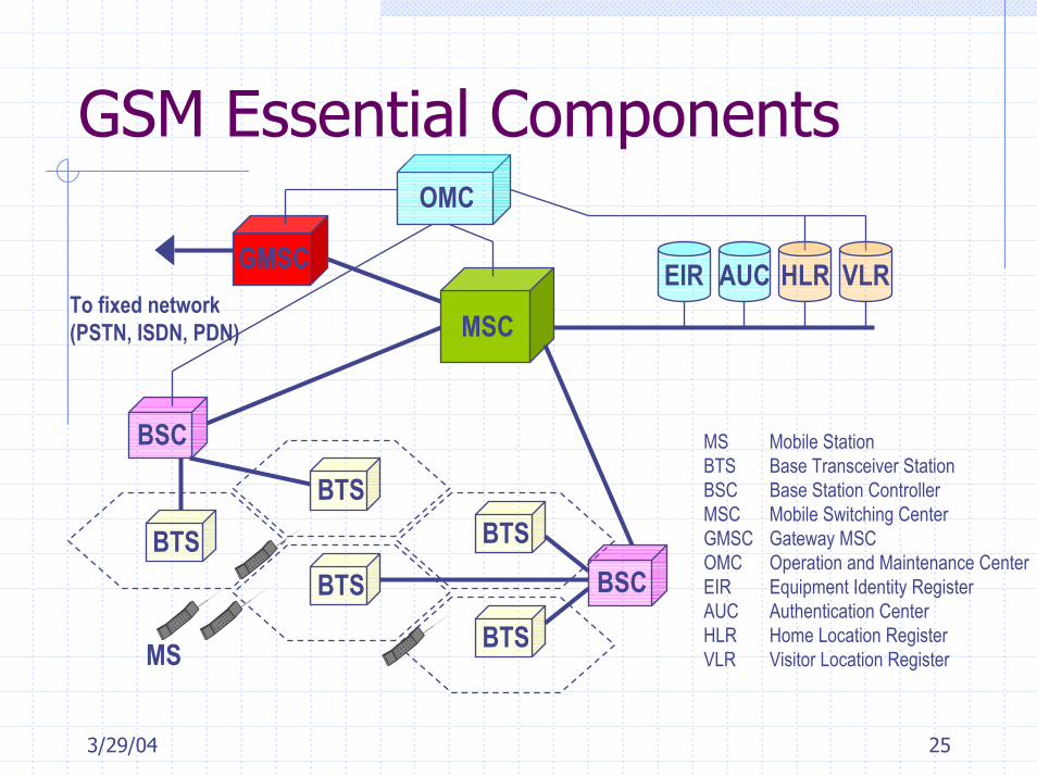
GSM Essential Components
BTS
BTSBTS
BTS
BTSBSC
GMSCTo fixed network (PSTN, ISDN, PDN)
MS
OMC
BSC
MSC
VLRHLRAUCEIR
MS Mobile StationBTS Base Transceiver StationBSC Base Station ControllerMSC Mobile Switching Center GMSC Gateway MSCOMC Operation and Maintenance CenterEIR Equipment Identity RegisterAUC Authentication CenterHLR Home Location RegisterVLR Visitor Location Register

3/29/04 26
Gateway MSC–GMSC
MSC
PLMNPublic Land
Mobile Network
MSCMSC
GMSC
Needed, as fixed networkswitches are not mobilecapable!!
GMSC task: query HLR forcurrent MS location
(if fixed network switcheswere able to query HLR,direct connection with local MSC would be available)
HLR
X X
X X
X

3/29/04 27
GSM Radio Spectrum2 x 25 Mhz band
Duplex spacing: 45 MHz124 carriers x band
200 KHz channelsSuggested use: only 122
Use top & bottom as additional guard
8 TDMA slots x carrierfull rate calls – 13 KbpsIf half-rate used, 16 calls at 6.5 kbps
Frequency [MHz]
890.2
890.4
“guard band”
1 2 3 4 5 6 7 8
( ) ( )[ ]( ) ( )[ ]MHz12.02.935
MHz12.02.890
−+=
−+=
nnF
nnF
dwlink
uplink
960
DOWNLINKBS MS
935
915
UPLINKMS BS
890

3/29/04 28
Adjacent Channels(due to GMSK)
35dB60dB
Specification: 9dBIn practice, due to power control and shadowing, adjacent channelsCannot be used within the same cell…

3/29/04 29
Physical Channel
200 KHz bandwidth + GMSK modulation1625/6 kbps gross channel rate (270.8333 kbps)
1 time slot = 625/4 bits156.25 bits15/26 ms = 576.9 µs
timeslot0 time
timeslot7
577 µs
1 frame = 60/13 ms = 4.615 ms26 frames = 120 ms (this is the key number)

3/29/04 30
Hybrid FDMA-TDMAphysical channel = (time slot, frequency)
577us 577us 577us 577us 577us 577us 577us 577us
frequency
200 KHz
200 KHz200 KHz
200 KHz
200 KHz
200 KHz
200 KHz
200 KHz
200 KHz
slot
Total n. of channels: 992
time

3/29/04 31
DCS 1800 radio spectrumGreater bandwidth available
EUROPE: 75 MHz band1710-1785 MHz uplink; 1805-1880 MHz downlink
ITALY: 45 MHz band from 20051740-1785 MHz uplink; 1835-1880 MHz downlink
Same GSM specification200 KHz carriers
A total of 374 carriers (versus124 in GSM)
DCS 1800 operatorsCommon rule in most of the countries:
First and second operators @ 900 MHz; Third etc @1800 MHzDCS 1800 deployment (1996+):
15 MHz (=75 carriers) to Wind; 7.5 (=37 carriers) to first and second operator (plus existing 27 GSM 900 carriers)

3/29/04 32
Other GSM BandsExtended GSM (E-GSM) band
Uplink: 880-915 MHzDownlink: 925-960 MHz
Other bands:450 MHz (450.4-457.6 up; 460.4-467.6 down)480 MHz (478.8-486 up; 488.8-496 down)1900 MHz (1850-1910 up; 1930-1990 MHz)

3/29/04 33
Duplexing- MS uses SAME slot number on uplink and downlink- Uplink and downlink carriers always have a 45 MHz separation
-I.e. if uplink carrier is 894.2 downlink is 919.2-3 slot delay shift!!
30 1 2 4 5 6 7UPLINK
31 2 5 6 70 4 DOWNLINK
MS: no need to transmit and receive at the same time on two different frequencies!

3/29/04 34
GP8.25
Structure of a TDMA SlotTB3
DATA57
S1
S1
Trainingsequence
26
Data57
TB3
Normal burst
148 bit burst156.25 bit (15/26 ms = 0.577 ms)
Symmetric structureDATA: 2 x 57 data bits
114 data bits per burst“gross” bits (error-protected; channel coded)“gross” rate: 24 traffic burst every 26 frames (120 ms)
22.8 kbps gross rate13 kbps net rate!
S: 2 x 1 stealing bit Also called stealing flags, toggle bitsNeeded to grab slot for FACCH (other signalling possible)

3/29/04 35
Tail & Training Bits
2 x TB = 3 tail bits set to 000At start and end of frameLeave time available for transmission power ramp-up/downAssures that Viterbi decoding starts and ends at known state
26 bit training sequenceKnown bit pattern (8 Training Sequence Code available)for channel estimation and synchronizationWhy in the middle?
Because channel estimate reliable ONLY when the radio channel “sounding” is taken!Multipath fading rapidly changes the channel impulse response…
3/29/04 36
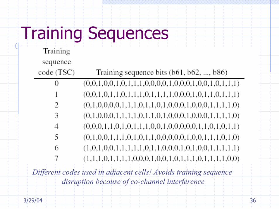
Training Sequences
Different codes used in adjacent cells! Avoids training sequencedisruption because of co-channel interference

3/29/04 37
Logical vs. Physical Channels
Physical channelsTime slots @ given frequenciesIssues: modulation, slot synchronization, multiple access techniques, duplexing, frequency hopping, etc
Logical channelsBuilt on top of phy channelsIssue: which information is exchanged between MS and BSS
Logical channels(traffic channels, signaling (=control) channels)
Physical channels(FDMA/TDMA)

3/29/04 38
GSM Logical Channels
MS BSSFast associated controlFACCH(dedicated to a specific MS)
MS BSSSlow associated controlSACCH(point-to-point signalling channels)
MS BSSStand-alone Dedicated control
SDCCHDedicated Control channel (DCCH)
BSS MSPagingPCH(used for access management)
BSS MSAccess GrantAGCH(point to multipoint channels)
MS BSSRandom AccessRACHCommon Control channel (CCCH)
BSS MSSynchronizationSCH
BSS MSFrequency CorrectionFCCH(same information to all MS in a cell)
BSS MSBroadcast controlBCCHBroadcast channel
MS BSSTCH half RateTCH/H
MS BSSTCH full rateTCH/FTraffic channel (TCH)
3/29/04 39
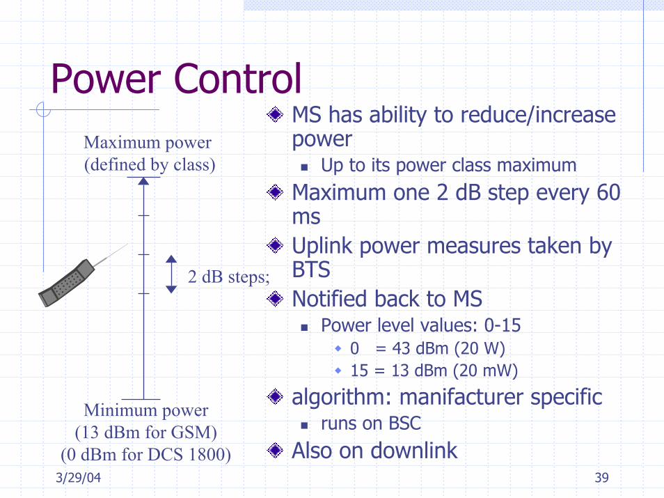
Power ControlMaximum power (defined by class)
Minimum power(13 dBm for GSM)
(0 dBm for DCS 1800)
2 dB steps;
MS has ability to reduce/increase power
Up to its power class maximumMaximum one 2 dB step every 60 msUplink power measures taken by BTSNotified back to MS
Power level values: 0-150 = 43 dBm (20 W)15 = 13 dBm (20 mW)
algorithm: manifacturer specificruns on BSC
Also on downlink

3/29/04 40
MS Powering Up
First operation when MS turned ON: spectrum analysis(either on list of up to 32 Radio Frequency Channel Numbers of current network)(or on whole 124 carriers spectrum)
3/29/04 41
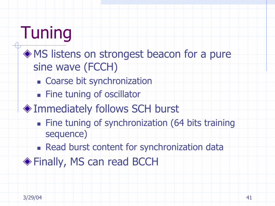
TuningMS listens on strongest beacon for a pure sine wave (FCCH)
Coarse bit synchronizationFine tuning of oscillator
Immediately follows SCH burstFine tuning of synchronization (64 bits training sequence)Read burst content for synchronization data
Finally, MS can read BCCH

3/29/04 42
Paging, 1Channel assignment:
only upon explicit request from MSPaging
needed to “wake-up” MS from IDLE state when incoming call arrives to MS
MS accesses on RACH to ask for a channel Generally SDCCH (but immediate TCH assignment is possible)
1) paging
BSS/MSC2) Random accessMS
3) Channel assignment
Paging channel: PCHAccess Grant Channel: AGCHRandom Access Channel: RACH
CCCHCommon ControlCHannel
PAGCH

3/29/04 43
Paging, 2
Paging message generated by MSC (receives incoming call)Transferred to subset of BSC
Paging limited to user’s location areaPaging message contains:
List of cells where paging should be performedIdentity of paged user
Paging message coded in 4 consecutive bursts over the air interfacePaging for more MSs may be joined in one unique paging message
3/29/04 44
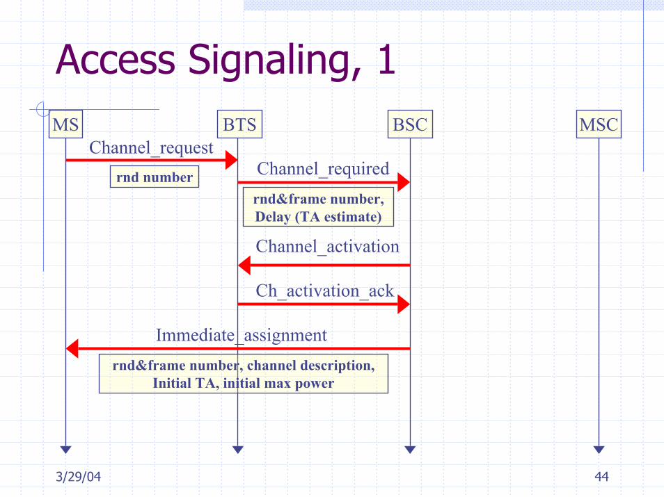
Access Signaling, 1MS BTS BSC MSC
Channel_requestrnd number Channel_required
rnd&frame number,Delay (TA estimate)
Channel_activation
Ch_activation_ack
rnd&frame number, channel description,Initial TA, initial max power
Immediate_assignment

3/29/04 45
Access Signaling, 2
MS BTS BSC MSC
Immediate_assignment… … … …
Initial_message
MS ID (IMSI or TMSI), MS capabilities (=classmark), establishment cause
Initial_message_ack (UA)
Copy of Initial message (including MS ID)
Establishment_indication
Further signaling: MSC to MS

3/29/04 46
Assignments
Read Chapter 9 of the textbook
Updated information on the class web
page:
www.ece.neu.edu/courses/eceg364/2004sp