Embed Size (px)
Citation preview

10/14/2016
10:5
4:0
1
AM
RE
VISIO
N
NO.
SHEET
NO.
INDEXDESCRIPTION:
REVISION
LAST
of DESIGN STANDARDS
FY 2017-18
s s
CONVENTIONAL LIGHTING
07/01/14 1 3 17500
Pole
Luminaire
Pull box
Ground rod
Luminaire
Ground Rod
Luminaire Cable
Luminaire Cable
Luminaire Cable
Breakaway Fuseholders
as 10 Amp fuse.
Slugs to be same size
with solid copper slugs.
Breakaway fuseholders
both lines to be fused.
fuse for line to line service
side with a 10 Amp slow blow
Breakaway fuseholder on 480V
Amp fuse.
Service). Slugs to be same size as 10
with solid copper slug (Line To Neutral
Breakaway fuseholders on Neutral side
Ground Wire (Bare)
#6 Solid Copper
Breakaway Fuseholders
#6 TW Green Bonding Ground
size as shown in plans. (Typical)
conduit. Circuit conductors and conduit
Circuit conductors in schedule 40 PVC
Surge Protective Device (SPD)
to line service both lines to be fused.
a 10 Amp slow blow fuse for line
Breakaway fuseholder on 480V side with
Amp fuse.
Service). Slugs to be same size as 10
with solid copper slug (Line To Neutral
Breakaway fuseholders on Neutral side
Ground Wire
#6 TW Green
clad with approved ground connection (At all pull boxes)
" diameter 20' long copper85U.L. approved Ground Rod
Access Panel
Equipment Ground Conductor
12" bed of Pearock or crushed stone for drainage
PVC Conduit
Copper Ground Wire (Bare)
1" PVC conduit with #6 Solid
PVC Conduit
Pole Ground Conductor
SPD Ground Conductor
Surge Protective Device (SPD)
Equipment Ground Conductor
for drainage.
or crushed stone
12" bed of Pearock
(Bare)
Wire
Ground
Copper
#6 Solid
Strain Relief Fitting (See Note #2)
(See Note #2)
Strain Relief Fitting
(See Note #2)
Strain Relief Fitting
Slugs to be same size as 10 Amp fuse.
Breakaway fuseholders with solid copper slugs. face of curb.
pavement or
Edge of traveled
Pole Wire Detail)
(See Metal
Pull Box
PVC conduit with Type TC Cable
Grounding Lug
(See Note #2)
Strain Relief Fitting
Length of Bracket Arm
Pole setback 20'
METAL POLE DETAIL
METAL POLE WIRING DETAIL
WIRING DIAGRAM
WIRING DETAILS
SURGE
ARRESTER
unless otherwise noted on plans
to prevent cable from slipping.
strain relief fittings or cable clamps at both ends of conduit
if the pole breaks away. Pull excess cable into pull box tighten
from the luminaire cable to provide tension on the fuseholders
base, pole base or pullbox for maintenance. Remove slack
2. Provide cable length to remove fuseholders from transformer
accordance with Section 992 of the Standard Specifications.
Barrier wall or bridge mounted poles: The wiring shall be in1.
NOTES:

10/14/2016
10:5
4:0
3
AM
RE
VISIO
N
NO.
SHEET
NO.
INDEXDESCRIPTION:
REVISION
LAST
of DESIGN STANDARDS
FY 2017-18
�
A A
CONVENTIONAL LIGHTING
01/01/12 2 3 17500
5'-
0"
5'-0"
SELECT MATERIAL
4"
6"
NOTES:
SLAB DIMENSIONS
SECTION A-A
LOCATIONPULL BOX
�
�
SLAB DETAILS FOR INTERMEDIATE PULLBOX LOCATIONS
in the price of pull box.
Concrete for slabs around pull boxes shall be included6.
adjusted as shown in the plans.
In urban areas or where space is limited slab dimensions may be
Slabs to be placed around all Poles and Pull Boxes in rural locations.5.
Section 635 of the Standard Specifications may be used.
The pull box shown is 13" x 24"; others approved under4.
Outside edge of slab shall be cast against formwork.3.
Concrete shall be Class NS with a minimum strength at 28 days of f'c=2.5 ksi.2.
Use compacted select material in accordance with Index 505.1.
24"
13"
Pull Box

10/14/2016
10:5
4:0
5
AM
RE
VISIO
N
NO.
SHEET
NO.
INDEXDESCRIPTION:
REVISION
LAST
of DESIGN STANDARDS
FY 2017-18
CONVENTIONAL LIGHTING
07/01/14 3 3 17500
Joint (Sealed)
" Expansion 21
Joint (Sealed)
" Expansion21
6"
4" SELECT MATERIAL
1'-9" 2'-6" 10"
7'-6"
4'-6"3'-0"
6'-
0"
Pull Box
2'-
6"
3'-
0"
NOTES:
�
�
SLAB DIMENSIONS
ST
RE
ET SID
E
SECTION B-B
LOCATIONPULL BOX
SHAFT LOCATION
BB
FOR POLE AND PULL BOX LOCATIONS
SLAB DETAILS
13"1'-4"
Typ.
24"
Typ.
requirements of Section 932.
pouring the slab and sealed with an APL approved Type A sealant meeting the
expansion material. The top ½" of expansion material shall be removed after
The expansion joint shall consist of ½" of closed-cell polyethelene foam 7.
in the price of pole or pull box.
Concrete for slabs around poles and pull boxes shall be included6.
adjusted as shown in the plans.
space is limited slab dimensions may be
Slabs to be placed around all Poles and Pull Boxes. In urban areas or where 5.
Section 635 of the Standard Specifications may be used.
The pull box shown is 13" x 24"; others approved under4.
Outside edge of slab shall be cast against formwork.3.
Concrete shall be Class NS with a minimum strength at 28 days of f'c=2.5 ksi.2.
Use compacted select material in accordance with Index 505.1.

10/14/2016
10:5
4:4
7
AM
RE
VISIO
N
NO.
SHEET
NO.
INDEXDESCRIPTION:
REVISION
LAST
of DESIGN STANDARDS
FY 2017-18
HIGH MAST LIGHTING
11/01/16 1 6 17502
HIGHMAST LIGHTING NOTES:
STANDARD POLE DESIGN NOTES
Specification Section 649-6.
B. After Installation: Place wire screen between top of foundation and bottom of baseplate in accordance with
A. Foundation: Specification Section 455 Drilled Shaft, except that payment is included in the cost of the Structure.
6. Construction:
B. Hot Dip Galvanize all other steel items: ASTM A123
A. Galvanize Anchor Bolts, Nuts and Washers: ASTM F2329
5. Coating:
6. Base Wall Thickness
5. Fy of Steel
4. Manufacturers’ Name3. Pole height
2. Pole Type
1. Financial Project ID
d. Include the following information on the ID Tag:
” diameter stainless steel rivets or screws. 81c. Secure to pole with
b. Locate on the inside of the pole and visible from the handhole.
a. 2”x 4” (Max.) aluminum identification tag. E. Identification Tag: (Submit details for approval.)
D. Hot Dip Galvanize after Fabrication.
" (Max.), prior to galvanizing.2
1C. Holes for Anchor Bolts: Anchor Bolt diameter plus
f. Circumferentially welded pole shaft, butt splices and laminated pole shafts are not permitted.
plus 6".
e. Longitudinal seam welds at telescopic field joints must be complete penetration welds for the splice length
d. Longitudinal seam welds within 6" of pole to base must be complete penetration welds.
c. Two longitudinal seam welds (Max.).
b. Pole Taper: Diameter changing at 0.14 inches per foot.
a. Round or 16-Sided (Min.)
B. Poles:
A. Welding: Specification Section 460-6.4
4. Fabrication:
I. Reinforcing Steel: Specification Section 415
H. Concrete: Class IV (Drilled Shaft)
G. Nut Covers: ASTM B26 (319-F)
c. Plate Washer: ASTM A36 (2 per anchor bolt)
b. Nuts: ASTM A563 Grade A Heavy-Hex (5 per anchor bolt)
a. Anchor Bolts: ASTM F1554 Grade 55
F. Anchor Bolts, Nuts and Washers:
E. Stainless Steel Screws: AISI 316
D. Weld Metal: E70XX
C. Pole Caps: ASTM A1011 Grade 50, 55, 60, or 65 or ASTM B209
B. Steel Plates: ASTM A709 or ASTM A36
c. ASTM A595 Grade A (55 ksi yield) or Grade B (60 ksi yield)
": ASTM A572 Grade 50, 55, 60 or 65163b. Greater than or equal to
": ASTM A1011 Grade 50, 55, 60 or 65163a. Less than
A. Poles and Backing Rings:
3. High Mast Structure Materials:
not detailed in the Plans.
2. Shop Drawings: This Index is considered fully detailed, only submit shop drawings for minor modifications
B. Eight (8) cylindrical luminaires with a maximum effective projected are of 1.5 sf and 77 lbs each.
A. One (1) cylindrical head assembly with a maximum effective projected area of 6 sf and 340 lbs (Max.)
1. Poles are designed to support the following:

10/14/2016
10:5
4:4
9
AM
RE
VISIO
N
NO.
SHEET
NO.
INDEXDESCRIPTION:
REVISION
LAST
of DESIGN STANDARDS
FY 2017-18
HIGH MAST LIGHTING
11/01/16 2 6 17502
Luminaire Head
(8 Maximum)
Luminaires
Handhole Door
Base Plate
Wire screen
Length Sectio
n (2)
Splice Length (1)
on Fill
to highmasts
Line adjacent
Natural Ground
(see Note #4E)
Identification Tag
shown for simplicity)
Pole (Faces not
Round or 16-Sided
Shaft
Drilled
(Max. Slope)21
25'
Maxim
um
Fill
Heig
ht
2'-0" Min.
Overall
Heig
ht
Length Sectio
n (1)
Joints
Tele
scopic Field
0.1
4 in/ft Taper,
Typ.
Length Sectio
n (n)
Joints
Tele
scopic Field
Splice Length (2)
ELEVATION POLE DESIGN TABLES
* Diameter Measured Flat to Flat
BASE PLATE AND BOLTS DESIGN TABLE
Design
Wind
Speed
Pole Overall
Height
Base Plate
Diameter
Base Plate
Thickness
Bolt
CircleNo.
Bolts
Bolt
Diameter
Bolt
Embedment
(ft) (in.) (in.) (in.) (in.) (in.)
130 mph
80 30.0 3.0 23.0 8 1.75 38
100 3.0 27.0 8 1.75 42
120 38.0 3.0 30.0 8 2.00 48
150 mph
80 30.0 3.0 23.0 8 1.75 43
100 36.0 3.0 28.0 8 2.00 47
120 44.0 35.0 8 2.25 52
170 mph
80 32.0 3.0 25.0 8 1.75 47
100 37.0 3.25 29.0 8 2.00 54
120 46.0 37.0 10 2.25 58
SHAFT DESIGN TABLE
Design
Wind
Speed
Pole Overall
HeightShaft
Diameter
Shaft
Length
Longitudinal
Reinforcement(ft)
130 mph
80 4'-0" 13'-0" 14- #11
100 4'-6" 14'-0" 16- #11
120 4'-6" 16'-0" 16- #11
150 mph
80 4'-0" 14'-0" 14- #11
100 4'-6" 16'-0" 16- #11
120 5'-0" 18'-0" 18- #11
170 mph
80 4'-6" 15'-0" 16- #11
100 4'-6" 17'-0" 16- #11
120 5'-0" 20'-0" 18- #11
POLE DESIGN TABLE*
Design
Wind
Speed
Pole Overall
Height (ft)Length
Wall
Thickness
(in.)
Minimum
Splice L.
Base Dia.
(in.)Length
Wall
Thickness
(in.)
Minimum
Splice L.
Base Dia.
(in.)Length
Wall
Thickness
(in.)
Minimum
Splice L.
Base Dia.
(in.)
130 mph
80 41'-0" 0.250 2'-0" 42'-0" 0.250 −− −− −− −− −−
100 23'-0" 0.179 2'-0" 41'-0" 0.250 2'-6" 0.250 −−
120 41'-0" 0.250 2'-0" 43'-0" 0.250 2'-9" 43'-0" 0.313 −−
150 mph
80 41'-0" 0.250 2'-0" 42'-0" 0.313 −− −− −− −− −−
100 23'-0" 0.179 2'-0" 41'-0" 0.250 2'-6" 43'-0" 0.313 −−
120 41'-0" 0.250 2'-6" 43'-0" 0.250 3'-0" 44'-0" 0.375 −−
170 mph
80 40'-0" 0.250 2'-3" 43'-0" 0.313 −− −− −− −− −−
100 23'-0" 0.250 2'-0" 42'-0" 0.313 2'-6" 44'-0" 0.375 −−
120 41'-0" 0.250 3'-0" 44'-0" 0.313 3'-6" 0.375 −−
34.0
3.875
3.875
5H:1V
4H:1V
3H:1V
2H:1V
Ground SlopeDrilled Shaft Diameter (ft)
ADDITIONAL SHAFT DEPTH DUE TO GROUND SLOPE (ft)
4 5
3
4
5
7
4
5
6
9
SECTION 1 (TOP) SECTION 2 SECTION 3
11
10
12
11
10
16
13
11
18
16
15
17
16
15
21
18
16
23
43'-0" 20
22
20
26
21
28
values in between those shown in the table, use the higher value.
additional shaft depth due to ground slope table. For slope or diameter
5H:1V and greater, increase the shaft depth in accordance with the
Foundation are assumed to be in level ground. For Foundation with slopes
NOTE:
45'-0"
Base Diameter
Pole Thickness (1" Min.)Inside Radius = Five Times
10/14/2016
10:5
4:5
4
AM
RE
VISIO
N
NO.
SHEET
NO.
INDEXDESCRIPTION:
REVISION
LAST
of DESIGN STANDARDS
FY 2017-18
HIGH MAST LIGHTING
11/01/16 3 6 17502
(See Table)
Equally Spaced.
Anchor Bolts
Handhole Ring
Base Plate
Edge of
Plate, and Pole
Shaft, Base
Center of Drilled
"411
6"
10"
Base
Bolt Circle
Base Plate
Drilled Shaft
Center of #5 Tie Bars
CSL tube (Typ.)
" x 6" Ring21
Padlock Tab
10"
1'-
8"
11"
1'-
9"
(Typ.)
Hinge Mount
Padlock Tab
" Plate Washer83
Nuts
Leveling
Shaft Diameter
Min.
2'-
0"
(Typ.)
6" Cover
Shaft Length
(Top)
4"
Cover
Anchor Bolts
1" x 1" Chamfer
"411
1'-
8"
12"
Min.
2'-
0"
Double Nuts (Typ.)
1:2 Max Slope
Finished Grade
see Spec. 649-6
Wire screen
Door
Handhole
Reinforcement)
(See Table For
Eq. Spaced
Reinforcement
Longitudinal
Shaft Length Is Based
On 2'-
0"
Heig
ht
Above Finis
hed
Grade
Nut Cover (not shown) for each bolt
height 'Jam' Nut. Provide individual
Double Nuts, Bottom Nut may be half
(Conduits Not Shown)
Joint
Partial Penetration
Diameter (Pole)
Diameter
(T = Wall Thickness)
(Min.)
2'-0" Lap
(Typ.)
6" Cover
(Anchor Bolts and Conduits Not Shown)
Shaft Diameter
"43
R=2
Full Pen.
Full Pen.
4"
4"
"43
R=2
Door
Handhole
" Thick41
Drilled Shaft
(Max.)
(1) Bolt Diameter
Thickness
Base Plate
Bolt Circle
measured flat to flat
Base Diameters
Tip Diameters or
Thickness
Wall
0.6 x Wall Thickness
Center of Arm
5"
7"
#5 Tie
s
Spacin
g
(Conduits Not Shown)
Diameter
Base Plate
Ring
Handhole
Drilled Shaft
Bolt E
mbed
ment
1"
SECTION E-E
SECTION C-C
SECTION B-BBASE PLATE AND ANCHORAGE ELEVATION
AA
E E
SECTION A-A
FOUNDATION PLAN
HANDHOLE RING HANDHOLE DOOR
BB
C C
POLE FOUNDATION
6 S
p.
@ 4"
Sp.
@ 1'-
0" (M
ax.)
to flat
measure center
Inside Radius
Base Plate
Opening
¼"
45 deg.
Wall Thk. + Ɗ"
2"X Ɓ" Backing Ring
¼"
2 X Bolt Diameter
Silicone Caulk
1" Min.
x Wall Thk.
(See welding note sheet 1)
Seam Weld (Typ.)
Anchor Bolt

10/14/2016
10:5
4:5
7
AM
RE
VISIO
N
NO.
SHEET
NO.
INDEXDESCRIPTION:
REVISION
LAST
of DESIGN STANDARDS
FY 2017-18
2'-
6"
2'
For Pull Boxes between Poles refer to Index 17500.3.
Slabs to be placed around all Poles and Pull Boxes.2.
Standard Specifications For Road And Bridge Construction.
At all pull boxes and pole bases, ends of conduit shall be sealed in accordance with Section 630 of the1.
NOTES:
HIGH MAST LIGHTING
01/01/12 4 6 17502
Pigtail Cord W/Female Receptacle
Male Inlet
conductors for grounding.
accommodate 2-4/0 and 2-#6
to winch support plate to
Straight Tongue, Two-Barrel)
Attach Copper Lugs (Two-Hole,
crushed stone for drainage.
12" bed of pearock or
#6 ground
4/0 ground
see Spec. 649-6
Wire Screen
or array.
grounding field
connected to
ground wire
4/0 Cu bare
wire.
bare ground
with 4/0 Cu
PVC conduit
Schedule 40
inside pole.
grounding lug
wire connected to
CU bare ground
4/0 AWG stranded
wire.
bare ground
with 4/0 Cu
PVC conduit
Schedule 40
approved ground rods.
" x 20' 85Minimum of (6)
joint (sealed)
" expansion83
and conduit size as shown in plans. (Typical).
Schedule 40 PVC conduit. Circuit conductors
approved ground connection.
diameter 20' long copper clad with
" 85U L approved ground rod
Twistlock disconnect
Circuit Breaker Panel Box.
fittings shall be used on all conductors entering
Panel Box for easy access. Service entrance
Arrester mounted to Top of Circuit Breaker
Circuit Breaker Panel Box with Surge
PVC conduit
Schedule 80
and conduit size as shown In plans. (Typical).
Schedule 40 PVC conduit. Circuit conductors
#6 Bonding Ground
be a minimum of 10'.
Interrod distances must
WIRING DETAILS
10/14/2016
10:5
4:5
9
AM
RE
VISIO
N
NO.
SHEET
NO.
INDEXDESCRIPTION:
REVISION
LAST
of DESIGN STANDARDS
FY 2017-18
HIGH MAST LIGHTING
01/01/12 5 6 17502
2" slip fitterCover
cables
Lift
Luminaires
Base plate
Lock nuts
Winch
Hand hole
for easy access.
at the front near hand hole
protector shall be mounted
the circuit breaker. The surge
be located in the pole with
A surge protector shall
Base plate
High mast pole
Pole Cable
position with Male Inlet.
luminaires when in the lowered
Covered receptacle to power
Luminaire support ring
Male Inlet
Power Cable Terminator
Lift cable sheaves
Head plate
Cover
switch
control
Remote
Slip clutch
Portable Motor(1) per project.
" heavy duty reversible or 1 HP 21
drill to pole shall be Stainless Steel.
All hardware for mounting heavy duty
Conduit
to Phase
480V Phase
Pull Box Rod
20' Ground
Grounding Array
4/0 Ground
Support Plate
Ground to Winch
Breaker
Circuit Panel
Lift cables (2 minimum)
by luminaire load.
Size of conductors to be determined
600 Volt rated Pole Cable.
Winch cable
by luminaire load.
Size of conductors to be determined
600 Volt rated Circuit Breaker Cable.
Female Plug
with Female Plug
Circuit Breaker Cable
same as Pole Cable.
25' minimum remote control cable
(see schematic)
drill & receptacle for supply cable.
120V. grounded receptacle for electric
Step-down transformer provided with
Ground Conductor
Equipment
and light distribution.
of luminaires, lamp wattage
See legend for number
& sheaves
Pole cable
Luminaire support ring
(equally spaced around ring)
2" Slip-fitter Assembly
Positive drive reversible winch
With Male Inlet
Power Cord
#6 Bonding Ground
ON
OF
F
Receptacle
Remote control switch
gnd.onoff
Supply cable receptacle
Luminaire
To
SCHEMATIC OF REMOTE AUXILIARY POWER UNIT
HIGH MAST POLE WIRING DIAGRAM
LOWERING DETAILS
SPD
shall correspond to the 0° axis of the refractor.
allow visual inspection of alignment. The marking
placed on the external face of the refractor to
lighting standard in the field. A marking shall be
photometric layout is physically produced at each
of these luminaires to ensure that the approved
attention must be exercised in the physical alignment
alignment of luminaire light distributions. Special
pole top. Particular attention is directed to
sheets detailing the mounting of luminaires at the
The contractor's attention is directed to those plan

10/14/2016
10:5
5:0
1
AM
RE
VISIO
N
NO.
SHEET
NO.
INDEXDESCRIPTION:
REVISION
LAST
of DESIGN STANDARDS
FY 2017-18
CC
�
HIGH MAST LIGHTING
07/01/14 6 6 17502
Joint (Sealed)
" Expansion 21
10'-0"
2'-0" Varies Varies 12"
5'
10'-
0"
" Expansion Joint (Sealed)21
6"
4" SELECT MATERIAL
6"
SECTION C-C
SHAFT LOCATION LOCATIONPULL BOX
SLAB DIMENSIONS
NOTES:
�
�
Pull B
ox
13"
SLAB DETAILS
Typ.
requirements of Section 932.
pouring the slab and sealed with an APL approved Type A sealant meeting the
expansion material. The top ½" of expansion material shall be removed after
The expansion joint shall consist of ½" of closed-cell polyethelene foam 7.
in the price of pole or pull box.
Concrete for slabs around poles and pull boxes shall be included6.
space is limited slab dimensions may be adjusted as shown in the plans.
Slabs to be placed around all Poles and Pull Boxes. In urban areas or where 5.
Section 635 of the Standard Specifications may be used.
The pull box shown is 13" x 24"; others approved under4.
Outside edge of slab shall be cast against formwork.3.
Concrete shall be Class NS with a minimum strength at 28 days of f'c=2.5 ksi.2.
Use compacted select material in accordance with Index 505.1.

UNDERGROUND FEED
1'
1'
5'-
6" (M
ax.)
5'-
6" (M
ax.)
5'-
6" (M
ax.)
5'-
6" (M
ax.)
10/14/2016
10:5
5:4
8
AM
RE
VISIO
N
NO.
SHEET
NO.
INDEXDESCRIPTION:
REVISION
LAST
of DESIGN STANDARDS
FY 2017-18
SERVICE POINT DETAILS
01/01/16 1 2 17504
Clevis With Insulators
By Power Company
Height Specified
Meter As RequiredBy Power Company
Height Specified
Meter As Required
Service DisconnectService Disconnect
As Required By Power Company
Conductor Weatherhead Height
Steel Conduit
Rigid Galvanized
"21Conductor In
Grounding Electrode
#6 AWG Insulated
Steel Conduit
Rigid Galvanized
" 21Conductor In
Grounding Electrode
#6 AWG Insulated
Concrete Pole Prestressed Type P-II, 36' Long
Concrete Pole, Prestressed Type P-II, 12' Long
Clad (All Service Points)
" Dia. 40' Long Copper 85
U.L. Approved Ground Rod,
Pull Box
Concrete Pad
And Ground Rod
Ground, Bond Wire,
Connection For Pole
And Ground Rod
Ground, Bond Wire,
Connection For Pole
Grade
Pull Box
Concrete Pad
Grade
For Drainage (Typ.)
Or Crushed Stone
12" Bed Of Pearock
For Drainage (Typ.)
Or Crushed Stone
12" Bed Of Pearock
4'
12'
8'
36'
29'
8'
7'
AERIAL FEED
DETAIL A DETAIL B
GENERAL NOTES:
4' (Min.)
4' (Min.)
4' (Min.)
4' (Min.)
4. A Pull Box is required at each service point, see Index 17700.
3. Shop drawings are not required for service equipment, unless noted in the plans.
and applicable local codes.
2. The service installation shall meet the requirements of the national electric code
as per the plans and service specifications.
1. It shall be the contractors responsibility to provide a complete service assembly
Ground Rod (T
yp.)
6" (Min.)
Depth To
(Typ.)
30"
(Typ.)
30"
Ground Rod (T
yp.)
6" (Min.)
Depth To
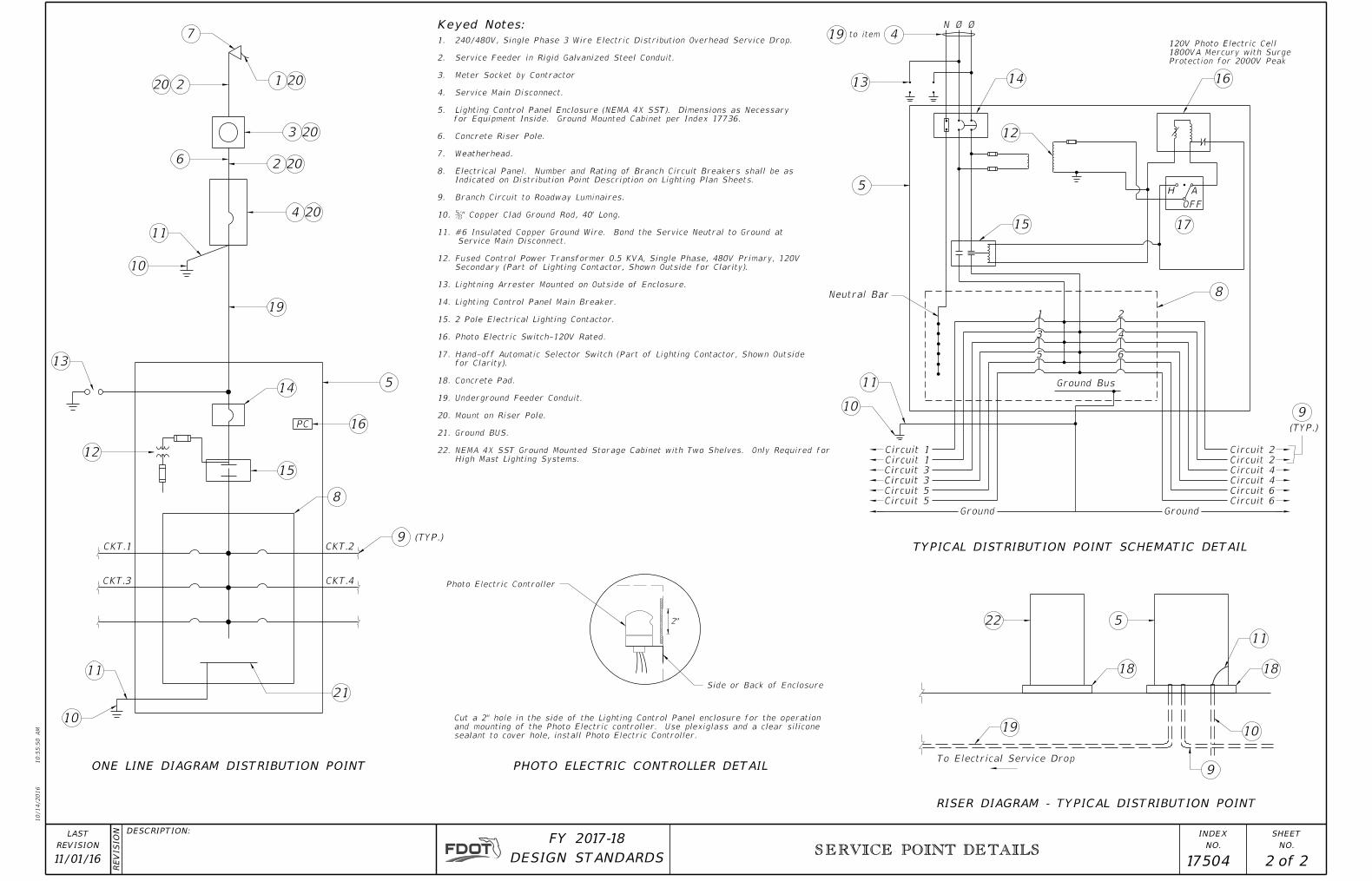
PHOTO ELECTRIC CONTROLLER DETAIL
High Mast Lighting Systems.
NEMA 4X SST Ground Mounted Storage Cabinet with Two Shelves. Only Required for 22.
Ground BUS.21.
Mount on Riser Pole.20.
Underground Feeder Conduit.19.
Concrete Pad.18.
for Clarity).
Hand-off Automatic Selector Switch (Part of Lighting Contactor, Shown Outside17.
Photo Electric Switch-120V Rated.16.
2 Pole Electrical Lighting Contactor.15.
Lighting Control Panel Main Breaker.14.
Lightning Arrester Mounted on Outside of Enclosure.13.
Secondary (Part of Lighting Contactor, Shown Outside for Clarity).
Fused Control Power Transformer 0.5 KVA, Single Phase, 480V Primary, 120V12.
Service Main Disconnect.
#6 Insulated Copper Ground Wire. Bond the Service Neutral to Ground at11.
ƅ" Copper Clad Ground Rod, 40' Long.10.
Branch Circuit to Roadway Luminaires.9.
Indicated on Distribution Point Description on Lighting Plan Sheets.
Electrical Panel. Number and Rating of Branch Circuit Breakers shall be as8.
Weatherhead.7.
Concrete Riser Pole.6.
for Equipment Inside. Ground Mounted Cabinet per Index 17736.
Lighting Control Panel Enclosure (NEMA 4X SST). Dimensions as Necessary5.
Service Main Disconnect.4.
Meter Socket by Contractor3.
Service Feeder in Rigid Galvanized Steel Conduit.2.
240/480V, Single Phase 3 Wire Electric Distribution Overhead Service Drop.1.
10/14/2016
10:5
5:5
0
AM
RE
VISIO
N
NO.
SHEET
NO.
INDEXDESCRIPTION:
REVISION
LAST
of DESIGN STANDARDS
FY 2017-18
SERVICE POINT DETAILS
11/01/16 2 2 17504
7
1 20220
3 20
2 20
4 20
11
10
19
5
13
12
15
14
16
8
21
11
10
9
15
14
5
13
17
16
419
10
11
9
8
522
10
18 18
11
9
19
Side or Back of Enclosure
6
12
Photo Electric Controller
PC
CKT.1
CKT.3
CKT.2
CKT.4
(TYP.)
ONE LINE DIAGRAM DISTRIBUTION POINT
AH
OFF
Protection for 2000V Peak
1800VA Mercury with Surge
120V Photo Electric Cell
to item
N Ø Ø
1
3
5 6
4
2
Ground Bus
Circuit 1
Circuit 1
Circuit 3
Circuit 3
Circuit 5
Circuit 5
Ground
Circuit 2
Circuit 2
Circuit 4
Circuit 4
Circuit 6
Circuit 6
Ground
(TYP.)
TYPICAL DISTRIBUTION POINT SCHEMATIC DETAIL
To Electrical Service Drop
RISER DIAGRAM - TYPICAL DISTRIBUTION POINT
2"
Keyed Notes:
Neutral Bar
sealant to cover hole, install Photo Electric Controller.
and mounting of the Photo Electric controller. Use plexiglass and a clear silicone
Cut a 2" hole in the side of the Lighting Control Panel enclosure for the operation
6" Otherwise
0" with Sidewalk
6'-
0"
To Metal Sign StructureGround Lug Attached
Luminaire
Sign Face
Pull Box
Drilled Shaft
Rigid Steel Conduit.
" Galvanized43THWN In
2-#10 AWG THW Or
" Galvanized Rigid Steel Conduit.21Lug In
Bond Wire To Run From Enclosure To Ground Maintaning Agency With Four Padlock Keys.
Padlock for the Enclosure. Provide The Away From Traffic. Install a Lockable
Amp Breaker, Mounted On Sign Structure Nema 3R Waterproof Enclosure With A 30
Then Properly Insulated & waterproofedSplices To Be Made With Compression Sleeves
Placed In Pull Box For Inspection Purposes. Clad With Approved Ground Connection To Be
" x 20' Copper85U.L. Approved Ground Rod
Hanger
Sign Structure Chord
Hanger
Sign Structure Chord
Sign
Luminaire
Wind Beam (Typ.)Zee Aluminum
Wind Beam (Typ.)Aluminum Zee
Bottom Hanger Pipe
Top Hanger Pipe
Caps (Typ.)
(See Sheet 2)Luminaire Support Structure
(See DETAIL 'A' Sheet 2)Luminaire Support Structure
(See DETAIL 'B' Sheet 2)Hanger Pipe Connection
calculations for each lighted sign for review by the Engineer.
The contractor may propose a different luminaire by submitting photometric
3. The Guide Sign Worksheet indicates the sign luminaire used for basis of design.
2. Luminaire spacing and arm length is shown on Guide Sign Worksheet.
requiring top luminaire support structures, the detail can be reversed.
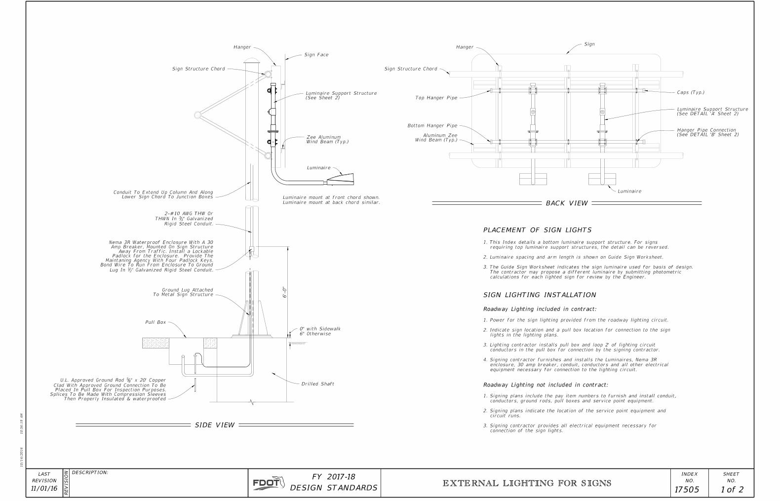
1. This Index details a bottom luminaire support structure. For signs
Lower Sign Chord To Junction BoxesConduit To Extend Up Column And Along
Luminaire mount at back chord similar.
Luminaire mount at front chord shown.
10/14/2016
10:5
6:1
9
AM
RE
VISIO
N
NO.
SHEET
NO.
INDEXDESCRIPTION:
REVISION
LAST
of DESIGN STANDARDS
FY 2017-18
EXTERNAL LIGHTING FOR SIGNS
11/01/16 1 2 17505
PLACEMENT OF SIGN LIGHTS
SIGN LIGHTING INSTALLATION
connection of the sign lights.
3. Signing contractor provides all electrical equipment necessary for
circuit runs.
2. Signing plans indicate the location of the service point equipment and
conductors, ground rods, pull boxes and service point equipment.
1. Signing plans include the pay item numbers to furnish and install conduit,
Roadway Lighting not included in contract:
equipment necessary for connection to the lighting circuit.
enclosure, 30 amp breaker, conduit, conductors and all other electrical
4. Signing contractor furnishes and installs the Luminaires, Nema 3R
conductors in the pull box for connection by the signing contractor.
3. Lighting contractor installs pull box and loop 2' of lighting circuit
lights in the lighting plans.
2. Indicate sign location and a pull box location for connection to the sign
1. Power for the sign lighting provided from the roadway lighting circuit.
Roadway Lighting included in contract:
SIDE VIEW
BACK VIEW

NOTES
SECTION B-B
Bolt Circle (4 Req'd)
" Ø Holes On 5" Ø169
3" Sch. 40 Pipe
" Sch. 40 Pipe212
To Roadway
¡ Set Parallel
" ¢216"x
SECTION A-A
" ¢216"x
" Sch. 40 Pipe212
Coupling(2 Holes Req'd)
Bolt Circles
Ø Bolt On 5" Ø
"21Drill & Tap For
PLATE 'A'
6"
4"
"4
32
"4
14
"83
Steel Plate
(Typ.)
" Ø Hole167
"4
3
"4
36
"8
31
89° ± 1
5'
" Pipe Cap212
" Sch. 40 Steel Pipe212
" Tee212
Threaded Nipple
" Sch. 40 Steel212
Plug
" Sch. 40 Steel Pipe212
" Pipe Coupling212
With Chain
Attach To Sleeve
Lock Washer;
" Mach. Bolt &41"x12
1
Pipe (18" Min.)
3" Sch. 40 Steel
"4
1
"4
1
Washers & Elastic Nut
Galvanized Bolt With Curved
" Ø41" Pipe For 2
1And 2
" Ø Hole Thru 3" Sleeve 165
Varie
s ~ 2'-
6"
Min.
PLATE 'A'PLATE 'A'
PLATE 'A'
Sleeve (Typ.)
" Pipe87"x28
3
Steel Pipe
" Sch. 40212
(Luminaire Support Structure)DETAIL 'A'
(Hanger Pipe Connection)DETAIL 'B'
Wind Beam (Typ.)
Sign
(2" Sch. 40 Pipe)
Hanger Pipe
¡ Bottom Or Top
(2" Sch. 40 Steel Pipe)
¡ Bottom Hanger Pipe
(2" Sch. 40 Steel Pipe)
¡ Top Hanger Pipe
I Beam Similar)
Beam Shown,
Hanger (Zee
Double Nuts
Washers And
" U-Bolt With 83
Double Nuts (2 Bolts Req'd)
" U-Bolt With Washers And 83
Double Nuts (2 Bolts Req'd)
" U-Bolt With Washers And 8
3
6''-0"
Max.
" Sch. 40 Steel Pipe212
"2
1± 2
Max.
"2
1± 2
Max.
Sign Face
See
Note #
5
10"
R
SleeveOf
Bottom
1'-
0"
" Reducing Coulpling 21" To 12
12
Hanger
Chord
Structue
Sign
Varie
s ~ 2'-
6"
Min.
Wind Beam (Typ.)
Aluminum Zee
(See DETAIL 'A')
Structure
Luminaire Support
See
Note #
5
LUMINAIRE SUPPORT STRUCTURE
(2" Sch. 40 Steel Pipe)
¡ Top Hanger Pipe
(2" Sch. 40 Steel Pipe)
¡ Bottom Hanger Pipe
1'-4"
Varries By Luminaire Type
¡ Of Luminaire
4'-0" (Unless Otherwise Shown In Plans) (6'-0" Max.)
10/14/2016
10:5
6:2
1
AM
RE
VISIO
N
NO.
SHEET
NO.
INDEXDESCRIPTION:
REVISION
LAST
of DESIGN STANDARDS
FY 2017-18
EXTERNAL LIGHTING FOR SIGNS
11/01/16 2 2 17505
2
"81
A AB B
"81
"81
"81
"81
"81
5. Chord O.D. + 5" (Min.)
4. All pipe dimensions are NPS.
ASTM A153.
shapes: ASTM A123, Fasteners and hardware:
3. Coating: Hot-Dip Galvanize pipes, plates, structural
E. Washers: ASTM F436
D. Hex Nuts: ASTM A563
C. Bolts: ASTM A307
B. Steel Plate: ASTM A36
A. Steel Pipe: ASTM A53 (Grade A or B)
2. Materials;
both ends of the horizontal pipe.
" U-Bolt, lock washers and hex nuts. Cap83 with a
1. Install hanger pipe to each vertical beam crossed

10/14/2016
10:5
7:2
1
AM
RE
VISIO
N
NO.
SHEET
NO.
INDEXDESCRIPTION:
REVISION
LAST
of DESIGN STANDARDS
FY 2017-18
STANDARD ALUMINUM LIGHTING
11/01/16 17515 1 8
GENERAL NOTES
7. Payment Note: Include the cost of the EJB in the cost of the median barrier or Traffic Railing it is embedded in.
c. Do not erect pole without Luminaire attached.
NCHRP Report 350 Guidelines (e.g. Akron Foundry TB1-17).
b. Certify the Base conforms to the current FHWA required AASHTO Frangibility Requirements, tested under
capacity.
a. Certify that the Clamp, Frangible Transformer Base, and Base Shoe Design are capable of providing the required
B. Frangible Base, Base Shoe, and Clamp:
A. Foundation: Specification Section 455, except payment for the foundation is included in the cost of the pole.
Construction:6.
C. Hot Dip Galvanize EJB and other steel items including poles: ASTM A123
B. Galvanize Steel Bolts, Screws, Nuts and Washers: ASTM F2329
A. Pole and Arm Finish: 50 grit satin rubbed.
5. Coatings/Finish:
3. Manufacturer’s Name2. Pole Height
1. Financial Project ID
d. Include the following information on the ID Tag:
” diameter stainless steel rivets or screws. 8
1c. Secure to transformer base with
b. Locate on the inside of the transformer base and visible from the door opening.
a. 2” x 4” (Max.) aluminum identification tag. J. Identification Tag: (Submit details for approval.)
d. Complete details and calculations for the reinforced 4”x 6” (Min.) handhole located 1’-6” above the base plate. capacity loads.
c. Test results showing the pole does not buckle at the shape transition area under the ultimate moment
the strong axis and 37 kip*ft in the weak axis.
” wall thickness achieves an ultimate moment capacity of 44 kip*ft in 16
5b. Tests demonstrating a pole with a
the strong axis and 30 kip*ft in the weak axis.
” wall thickness achieves and ultimate moment capacity of 36 kip*ft in 4
1a. Tests demonstrating a pole with a
fabrication:
free pole. The fabricator’s Department-approved QC Plan must contain the following information prior to I. For Median Barrier Mounted Aluminum Light Poles, the fabricator must demonstrate the ability to produce a crack
c. Provide a watertight cover with neoprene gasket and secure cover with galvanized screws.
b. Hot Dip Galvanize after Fabrication.
a. Weld all seams continuously and grind smooth.
H. Embedded Junction Boxes (EJB):
G. Perform all welding in accordance with AWS D1.2.
F. Equip poles located on bridges, walls and concrete median barriers/Traffic Railings with a vibration damper.
E. Provide 'J', 'S' or 'C' hook at top of pole for electrical wires.
7” oblong and 6” round respectively to simplify fabrication. oblong base. Portions of the pole near the base and at the arm connections may be held constant at 11”x
D. Median Barrier Mounted Light Pole Taper: Taper as required to provide a 6” O.D. round top with an 11” x 7” O.D. simplify fabrication.
of the pole near the base shoe and at the arm connections may be held constant at 10” and 6” respectively to C. Roadway Light Pole Taper: Taper as required to provide a round top O.D. of 6” and a base O.D. of 10”. PortionsB. Upright Splices: Not Allowed. Transverse welds are only allowed at the base.
temper after welding.
A. Weld Arm and Pole (Alloy 6063) in the T4 temper using 4043 filler. Age the Arm and Pole artificially to the T6
4. Fabrication:
L. Reinforcing Steel: Specification Section 415
K. Concrete: Class 1
J. Nut Covers: ASTM B26 (319-F)
I. Stainless Steel Fasteners: ASTM F593 Alloy Group 2, Condition A, CW1 or SH1
c. Plate Washer: ASTM A36
b. Nuts: ASTM A563 Grade A Heavy-Hex
a. Anchor Bolts: ASTM F1554 Grade 55
H. Anchor Bolts, Nuts, and Washers:
c. Washer: ASTM F436 Type 1
b. Nuts: ASTM A563 Grade DH Heavy-Hex
a. Shoe Base Bolts: ASTM F3125, Grade A325, Type 1
G. Bolts, Nuts and Washers:
F. Transformer and Frangible Base Materials: ASTM B26 or ASTM B108, Alloy 356-T6
E. Aluminum Weld Material: ER 4043
ASTM A709 or ASTM A36 Grade 36 :D. Steel Bearing Plate
C. Caps and Covers: ASTM B-26, Alloy 319-F
B. Bars, Plates, Stiffeners and Backer Ring: ASTM B221, Alloy 6063-T6
A. Pole, Pole Connection Extrusions and Arm Extrusions: ASTM B221, Alloy 6063-T6
3. Materials:
included in the Plans.
2. Shop Drawings: This Index is considered fully detailed, only submit shop drawings for minor modifications not
B. Weight: 75 lb.
A. Luminaire Effective Projected Area (EPA): 1.55 SF
1. Poles are designed to support the following:
10/14/2016
10:5
7:2
4
AM
RE
VISIO
N
NO.
SHEET
NO.
INDEXDESCRIPTION:
REVISION
LAST
of DESIGN STANDARDS
FY 2017-18
DANGER
HIGH VOLTAGE DO NOT TAMPER
DANGER
HIGH VOLTAGE DO NOT TAMPER
DANGER
HIGH VOLTAGE DO NOT TAMPER
DANGER
HIGH VOLTAGE DO NOT TAMPER
STANDARD ALUMINUM LIGHTING
11/01/16 17515 2 8
Straight
2'-6"
Straight
2'-6"
to poles on fill
Line adjacent
Natural Ground
on Sheet 4
foundation see details
2'-6" Ø Concrete
Finished Grade
� Pole
shown in Tables.
2'-6" to foundation depths
for grades up to 1:2 add
Grade flatter than 1:4
� Pole
Stainless Steel Set Screws (Typ.)
Cap attached to pole with 3
6" Ø Pole top with Cast Aluminum
to oblong shape
from round shape
Transition zone
Begin Pole Taper
Head screws.
and cover with Hex
with reinforced frame
4"x6" (Min.) Handhole
(See Roadway Plans)
Finished Grade
to poles on fill
Line adjacent
Natural Ground
See Sheet 3 (Typ.)
3'-0" or 5'-6"
see Sheet 3 (Typ.)
For Fixture Arm Details
to oblong shape
from round shape
Transition zone
Head screws.
and cover with Hex
with reinforced frame
4"x6" (Min.) Handhole
Begin Pole Taper
(See Roadway Plans)
Finished Grade
to poles on fill
Line adjacent
Natural Ground
(Typ.)
see Sheet 4
Base Shoe Casting
10" Ø Pole Base in
Base see Sheet 4
Transformer
Breakaway
17" High Frangible/
Internal Vibration Damper Internal Vibration Damper
A A A A
Win
d
Desig
n
Heig
ht at Fixture (F
or Pole
Desig
n)
Pole
Heig
ht
Fixture
Mountin
g
Heig
ht (fro
m Lig
htin
g
Desig
n Requir
em
ents)
Fixture Arm Length
Fixture
Mountin
g
Heig
ht (fro
m Lig
htin
g
Desig
n Requir
em
ents)
Win
d
Desig
n
Heig
ht at Fixture (F
or Pole
Desig
n)
40'
Desig
n
Mountin
g
Heig
ht (F
or Pole
Desig
n)
Pole
Heig
ht
25'
Max.
Fill
Heig
ht
70'
Max.
Fill
Heig
ht
Taper
Varie
s
Taper
Varie
s
Taper
Varie
s
Win
d
Desig
n
Heig
ht at Fixture (F
or Pole
Desig
n)
40'
Desig
n
Mountin
g
Heig
ht (F
or Pole
Desig
n)
Pole
Heig
ht
22'-
5"
(8', 10' or 12' only)
Fixture Arm Length
7"
70'
Max.
Fill
Heig
ht
1'-
6"
22'-
5"
(8', 10' or 12' only)
Fixture Arm Length
11"
7"
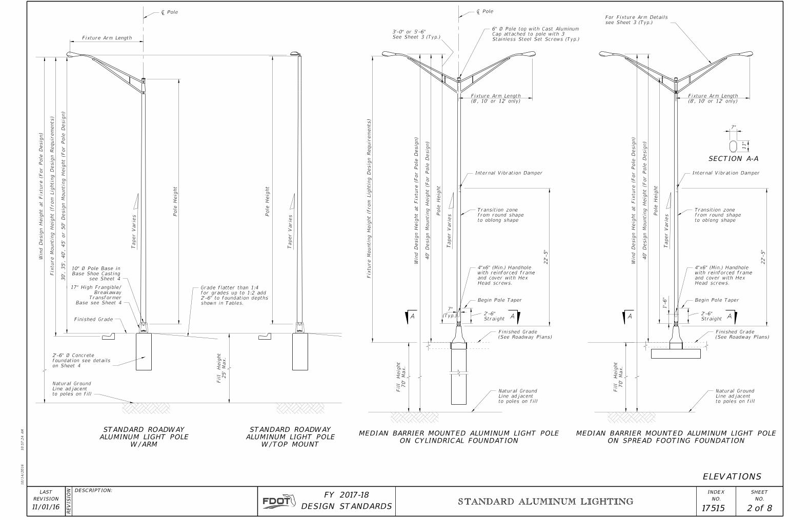
SECTION A-A
ON SPREAD FOOTING FOUNDATION
MEDIAN BARRIER MOUNTED ALUMINUM LIGHT POLE
ON CYLINDRICAL FOUNDATION
MEDIAN BARRIER MOUNTED ALUMINUM LIGHT POLE
ELEVATIONS
Taper
Varie
sPole
Heig
ht
W/ARM
ALUMINUM LIGHT POLE
STANDARD ROADWAY
W/TOP MOUNT
ALUMINUM LIGHT POLE
STANDARD ROADWAY
30', 35', 40', 45'
or 50'
Desig
n
Mountin
g
Heig
ht (F
or Pole
Desig
n)

10/14/2016
10:5
7:2
7
AM
RE
VISIO
N
NO.
SHEET
NO.
INDEXDESCRIPTION:
REVISION
LAST
of DESIGN STANDARDS
FY 2017-18
Watertight
Watertight
Dim
ple (s
ee
Detail)
4.634.63140 15
3.63 0.1888160
0.188
140
3.633.63 0.188
3.6312 3.63
160
4.634.63
4.63 0.3130.31315 4.63
10 3.63160
3.63 0.188
160 12
3.63
10
3.63 0.1880.1258 3.63
0.188 3.633.63120 10
Upper Arm Lower Arm
ARM TABLE
(mph)
Speed
Wind
Weld (in)
120
Weld (in)
140 8
0.1880.188 4.63
0.188
140
3.633.63 0.188
3.63 0.18812
0.188
120
15 4.63120
3.63 0.188
(ft)
Length
Arm
O.D. (in) O.D. (in)
0.250
0.250
0.250
0.250
0.250
0.250
0.250
0.250
STANDARD ALUMINUM LIGHTING
11/01/16 17515 3 8
At Lower Arm
Welded Cap
Press on or
Upper Arm
Vertical Axis
by Vendor
Supplied
Extrusion
Connection
of Upper Arm Only
Extrusion at Base
Hole in Connection
Provide 2" Ø Wiring " Long4
3"x281L 3x2x
" Ø Tapped Hole83
(See Cap Details)
Vinyl Cap (both ends)
" High Temp211
ASTM A36 Hot Rolled Rod
" long41" Ø x 112
11
B221 Alloy 6063-T6
Aluminum Pipe ASTM
2" x 12" Long Sch. 10
" Long (Typ.)43"x28
1L 3x2x
" Ø Tapped Hole83
surface
Spherical
" Ø41
� Fixture Arm
Level
Luminaire Attachment
" O.D.) for83Slipfitter (2
2" Nominal Pipe Size
See Arm Section Above
Upper Arm Tube
" O.D. x 0.125 (Min.)21Strut - 1
Face of Pole
� Arm at
Mounted Aluminum Light Poles
is only for Median Barrier
Double arm configuration
of Pole where Shown.
and a Split Lockwasher Each Side
" O.D. Flat Washers81and 2-1
Steel Bolts with Hex Nuts
" Ø Stainless21Provide
PVC Type 65500
ASTM D2287
" Ø Tapped Hole83
" Chamfer (Typ.)43
" Ø Tapped Hole83
B221 Alloy 6063-T6
Aluminum Pipe ASTM
2" x 12" Long Sch. 10
1" Min. I.D. Rubber Grommet
at � of Upper Arm for� of Wiring Hole in Pole
" From the Base Weld21of Arm Tubes 1
" (Min.) Drain Holes in Underside 81Provide
See Arm Section Above
Lower Arm Tube -
4" Min. Radius at Bend
Material Specification
See General Notes on Sheet 1 for
Pole Connection Extrusion (Typical)
163
Outside
Diameter
"8
32
Arm Data Tables
See "O.D." in
163
Lo
wer
Ar
m
Upper
Ar
m
&
Thickness (Nominal)
" Wall81*
for Weld Size.
See Arm Data Tables
Connection Extrusion.
Fillet Weld Arm Tube to
"±418
6"
(Connection At Lower Arm Similar)
81
"8
7
81"
87
1'-
2"
1'-
4"
"8
7
" Deep161
"831"8
31
3"
"2
11
"432
"2
11
" ID2112
" 1"
1"
Fixture Arm Length = 8', 10', 12' or 15'
3 x (Fixture Arm Length - 3'-0") / 43'-0"
6" 1'-4"
1'-0"
2°
6"
163
1'-
9"
6"
1
Varies
As Required
(Fixture Arm Length - 3'-0") /4
� Pole
upper and lower arms.
" at the83The outside diameter about the minor axis should be held at 2
Association Tolerances.
" nominal and within the Aluminum81provide minimum wall thickness of
area of the section equal or exceed that of the required section, and
tabulated, provided the section properties about the vertical axis and the
The fabricator may substitute elliptical cross sections other than those
connection.
Uniformly transition elliptical section to a cylindrical section at the arm
shown in the ARM SECTION and as tabulated in the ARM DATA Tables.
At the pole connections, provide arm tube extrusions with dimensions as
ARM TUBE EXTRUSIONS NOTES:
Detail
Connection
See Arm
4'-
6"
Maxim
um Radiu
s
Tube Extrusion Note
This Point - See Arm
" O.D. Pipe Beyond832
5'-6" (12' and 15' Fixture Arm Lengths)
3'-0" (8' and 10' Fixture Arm Lengths)
DIMPLE DETAIL
VIBRATION DAMPER ELEVATION
VINYL CAP DETAIL
HIGH TEMP
VIEW B-B
VIEW C-C
ARM CONNECTION DETAIL
ARM SECTION
SECTION A-A
ARM ELEVATION
C
B
C
B
A
A
ARM & DAMPER DETAILS
Connection
Saddle, or Other Acceptable
Side of Arms, Extruded
" Ø x 3" Bar Each21
Connection Weld Sizes Shown in the Arm and Pole Tables.
Minimum Requirements of the Welding Code for the
Increase Member Wall Thickness as Necessary to Meet*
6"
3"

3"
2Ƅ" ϕ
160
0.313
12,15 0.37545
0.188160 8,10 0.37545
0.313
8,10,12140 50 0.1880.375
12,15140 45 0.1880.313
0.313
8,10,12,15160 40 0.1880.313
0.31315140 50 0.375
(mph)
Speed
Wind
POLE TABLE WITH ARM
(ft)
Arm Length
5010,12,15 0.313 0.188120
508 0.313 0.125
140
458,10 0.313 0.125140
408,10,12,15 0.125
0.188 0.125
120
0.1888,10,12,15
wall (in)
Pole
Height (ft)
Mounting
Design
Weld (in)
Upper
120
Weld (in)
Lower
8,10
45 0.188
120
12,15
45 0.125
120
0.25
grades up to 1:2 add 2'-6" to foundation depths shown in table.
** Depths shown in table are for grades flatter than 1:4, for
NOTE:
minimum Aluminum Association thicknesses are not violated.
are permitted and tapered walls may be used provided the
shall be within the Aluminum Association Tolerances. Thicker walls
Pole wall thicknesses shown in the POLE TABLE are nominals and
35 & 40
120 8,10,12,15 0.125 0.125 0.12530
140 35 0.125
140 8,10,12,15 30 0.1250.188 0.188
8,10 0.188 0.188
8,10,12,15160 35 0.125
8,10,12,15160 30 0.125
0.25
0.188 0.188
160
850140
7
845 & 50160
120 6
(mph)
Wind Speed
(FT)**
Depth
Total
Height (ft)
Mounting
Design
140 630 & 45
120 745 & 50
FOUNDATION TABLE W/TOP MOUNT
30, 35 & 40
7140 40 & 45
160 30 6
35 & 40
45 & 50140 8
140 7
160 8
30 & 35160 7
(FT)**
Depth
Total
Height (ft)
Mounting
Design
(mph)
Wind Speed
FOUNDATION TABLE W/ARM
120
850120
630 & 35
7120 40 & 45
30, 35 & 40
40 & 45
0.250
0.250
0.250
0.250
0.250
0.250
0.250
0.250
0.250
0.250
0.250
0.250
0.250
POLE TABLE WITH TOP MOUNT
(mph)
Speed
Wind
wall (in)
Pole
Height (ft)
Mounting
Design
Weld (in)
Upper
0.2500.188
160 0.25040
0.313
0.1250.250 0.250
50140
0.125
50160 0.375 0.3130.250
0.250160
0.250
45 0.1880.313
45120 0.188 0.1880.125
0.188120
Weld (in)
Lower
40 0.1250.188
120
0.1250.188 0.188
45140
0.25050 0.125
140
0.250
0.125120 0.1250.12530 & 35
0.1250.125 0.12530140
35 & 40
160 30 0.1250.125
160 35 0.125
0.125
0.188 0.188
140 35 0.1250.250 0.25012, 15
STANDARD ALUMINUM LIGHTING
11/01/16 17515 4 8
5/25/2017
8:2
2:5
7
AM
RE
VISIO
N
NO.
SHEET
NO.
INDEXDESCRIPTION:
REVISION
LAST
of DESIGN STANDARDS
FY 2017-18
Slots for 15" Bolt Circle
Tie Bars *
Shaft is Installed.
as Shown when the
Anchor Bolts Oriented
4 - Equally Spaced
in Pole Base Elevation
Anchor Bolt, See Note
1" Chamfer
(Typ.)
Elbow 1" Min.
Conduit with
Nuts (Typ.)
Double
or Placed in Conduit
Wire Cast in Concrete
#6 AWG Bare Ground
Attachment Optional
Nut Cover - Bolted
Pressure Mounted
Cast Aluminum
(Typ.)3"
Cov
er
6'-
0"
Minim
um
(See Pole
Data Table
s for
Depth Requir
ed)
Tie Bars *
1"
8~#7 Bars
Equally Spaced
Minim
um E
mbed
ment
3'-
6"
4"
4"
Min.
1'-
5"
10" O.D. Shaft
2'-6" Ø
� Arm� Pole &
� Arm� Pole &
Tenon
Nut and Washer
Shoe Base Bolt with
3ƀ"
3ƀ"
Shoe 13ƀ" Bolt CircleSlots for Cast Aluminum Base
"16
55
"16
55
With "Flowable Fill" Backfill
Cast-in-Place or Precast
Class I Concrete may be
General Notes on Sheet 1
Transformer Base. See
Frangible/Breakaway
Cast Aluminum
Sheet 1
Notes on
See General
Base Shoe
Cast Aluminum
Base Manufacture (Typ.)
Breakaway Transformer
as Required by Approved
Anchor Bolt and Washer
DANGER
HIGH VOLTAGE DO NOT TAMPER
1'-0"
Lap
Equally Spaced
8 - #7 Bars
Typ.
45°
Bolt CircleTypic
al
Each
Way
for Lower Weld Size
See Pole Data Tables
to Inside of Base Shoe.
Fillet Weld Butt of Pole
for Upper Weld Size.
See Pole Data Tables
to Inside of Base Shoe.
Fillet Weld Outside of Pole
for Wall Thickness
See Pole Data Tables
SECTION C-C
TRANSFORMER BASE
TOP VIEW
TRANSFORMER BASE
BOTTOM VIEW
VIEW B-B
FOUNDATION
POLE BASE ELEVATION
B
C
B
C
1'-3" Ø
POLE AND BASE DETAILS FOR ROADWAY ALUMINUM LIGHT POLE
TOP MOUNT TENON
turns top and 1 flat turn bottom.
#4 Tie Bars @ 12" centers (max.) or D10 (or W10) spiral @ 6" pitch, 3 flat*

11/1/2016
11:1
6:1
8
AM
RE
VISIO
N
NO.
SHEET
NO.
INDEXDESCRIPTION:
REVISION
LAST
of DESIGN STANDARDS
FY 2017-18
130° (Typ.)
not violated.
provided the minimum Aluminum Association thicknesses are
Thicker walls are permitted and tapered walls may be used
and shall be within the Aluminum Association Tolerances.
Pole wall thicknesses shown in the POLE TABLE are nominals
NOTE:
(MPH)
SPEED
WIND
120
140
160
(FT)
ARM LENGTH
8, 10, 12
8, 10, 12
8, 10, 12
HEIGHT (FT)
MOUNTING
DESIGN
40
40
40
WALL (IN)
POLE
0.25
0.25
0.313
(FT)
FILL HEIGHT
Up to 70'
Up to 70'
Up to 70'
STANDARD ALUMINUM LIGHTING
11/01/16 17515 5 8
(2 required)
Bend as shown
"21"x5"x102
1
Stiffener Plate
& � Light Pole� Base Plate
top and bottom
threaded 8" min.
" Ø Anchor Bolt411
Base Plate
Leveling Nut
permitted (Typ.)
Galv. Coupler
" Plate Washer41
" Plate Washer41
Traffic Railing
Top of
Hole (Typ.)
" Ø16
5� 1
Hole (Typ.)
" Ø1651
Hole (Typ.)
" Ø21� 1
"x3" Backer Ring41
Stiffener Plate
Outer Wall of Pole
& � Light Pole� Base Plate
Pole Wall"x3" Backer Ring4
1
Stiffener Plate Detail)
Stiffener Plate (see
"x3" Backer Ring41
& � Light Pole� Base Plate
& � Light Pole� Base PlateHole (Typ.)
" Ø211
See Note 2
Double Nuts
1'-6"
"417 "4
31
"2132"2"
"417
"213
"431
Hole4
" Ø
Penetration Weld
Full
Penetration Weld
Full
8"
"4
12
"4
31
"2
13
"2
13
"4
12
"4
31
"4
12
"2
1
" R (Typ.)21
4"
"83
"4
3
5"
2"
3" " fillet reinforcing4
3"x83w/
Full penetration weld
" Min.41
2"
1 Bolt Dia. (Max.)
"212
"411
1'-5"
"211'-2
1'-0""212
"411
"2
1
7"
"2
14
"4
11 "
21
22"
"2
12"
41
1
POLE TABLE
BEARING PLATE PLAN
BEARING PLATE ELEVATION
DETAIL 'A'
STIFFENER PLATE DETAIL
BASE PLATE PLAN
BASE PLATE ELEVATION
BASE PLATE DETAILS FOR MEDIAN BARRIER MOUNTED ALUMINUM LIGHT POLE
NOTE:
for each bolt.
3. Provide individual nut covers (not shown)
substituted by a half height 'Jam' nut.
2. Double Nuts: The bottom hex nut may be
Plates and Detail 'A' see Sheets 6 & 7.
1. For locations of Bearing Plates, Base

10/14/2016
10:5
7:3
5
AM
RE
VISIO
N
NO.
SHEET
NO.
INDEXDESCRIPTION:
REVISION
LAST
of DESIGN STANDARDS
FY 2017-18
(Similar to Bars 5S)
#5 Bars, 4' long (Typ.)
(Typ.)
5ƀ"
STANDARD ALUMINUM LIGHTING
11/01/16 17515 6 8
about � Light PoleSymmetrical
� Roadway Concrete Barrier Wall
12 ~ #4 Bars @ 8"
1" Ø Conduit
#5 Bars, 4' long (Typ.)
Bars 5R @ 8" (Typ.)
1" Ø Conduit for grounding
2" Ø Conduit2" Ø Conduit
#5 Bars @ 8"
Bearing Plate
Bars 5W1 Bars 5W1
@ 8"
Bars 4D
See Roadway Plans
16 ~ #4 Bars @ 8"
Bearing Plate
2" Ø Conduit
See Roadway Plans
details, see Sheet 5
For Base Plate
Construction Joint permitted
2" Ø Conduit1" Ø Conduit
with Gasket
Cover Plate
Screws (Typ.)
Galvanized
1" Ø Conduit
1" Ø Conduit
2" Ø Conduit
Embedded Junction Box
� 1'-0" x 1'-3" x 6" (Typ.) 4 ~ 1Ɓ" Ø Anchor Bolts
ƅ" Ø x 20' Grounding Rod
Optional Const. Jt. (See Note 2)
(Similar to Bars 5W)
Bars 5W1 @ 8"
#4 Bars @ 8"
Rigid Pavement only
Material with
1" Exp. Jt.
Bars 4D @ 8"
2 ~ #5 Bars
@ 8"
Bars 4D
16 ~ #5 Bars @ 8"±
@ 8"
Bars 4D
(Typ.) (See Note 2)
Optional Const. Jt.see Index 421
position details,
For reinforcing steel
Details, see Index 410
3. For adjacent Concrete Barrier
Index 410.
2. Dowel Construction Joint per
Sheet 5.
1. For Bearing Plate Details, see
NOTES:
6"
11'-0"
5'-6"5'-6"
7'-3" 4'-
0"
8'-
0"
2'-
0"
4'-
0"
@ construction joint
Provide dowel bars
(Reinforcing steel not shown)
Wall
1'-
0"
1'-
6"
11'-0"
4"
2'-
6"
Sheet 5
See Detail 'A'
2'-0"
5" "219 5"
1'-
10"
2'-
9"
3'-
7"
7"
3"
1"
1'-
0"
1'-
6"
2'-
6"
8'-0"
3"
(Typ.)16
3
1'-
0"
3"
6"1'-3"
1'-
0"
4" 4"
FRONT VIEW VIEW A-A
A
A
END VIEW
PLAN
ELEVATION
SPREAD FOOTING DETAILS FOR MEDIAN BARRIER MOUNTED ALUMINUM LIGHT POLE
(Box and Cover)
4" Cover
(Bottom)
3" Cover
(Top and sides)
4" Cover
(Bottom)
EMBEDDED JUNCTION BOX DETAILS
2Ɓ" 2Ɓ"
3ƀ" 3ƀ" 1ƀ"
(For Roadway Concrete Barrier Wall reinforcing steel see Roadway Plans)
(Min.)
Ɓ" (Typ.)
3'-0"2'-0"
approach ends and guardrail.
Min. 10' from free end, barrier wall transition,
B
B
2'-
9"
2'-3"
8"
1'-
11"
2'-
5"
3"
"439
3"
10"10"
2'-
5"
11"
BAR BENDING DIAGRAMS
BARS 4D
BARS 5W1
BARS 5R
8Ɓ" 8Ɓ"
1'-4ƀ"
3Ƃ"
Bars @ 8"
12 ~ #5
10/14/2016
10:5
7:3
7
AM
RE
VISIO
N
NO.
SHEET
NO.
INDEXDESCRIPTION:
REVISION
LAST
of DESIGN STANDARDS
FY 2017-18
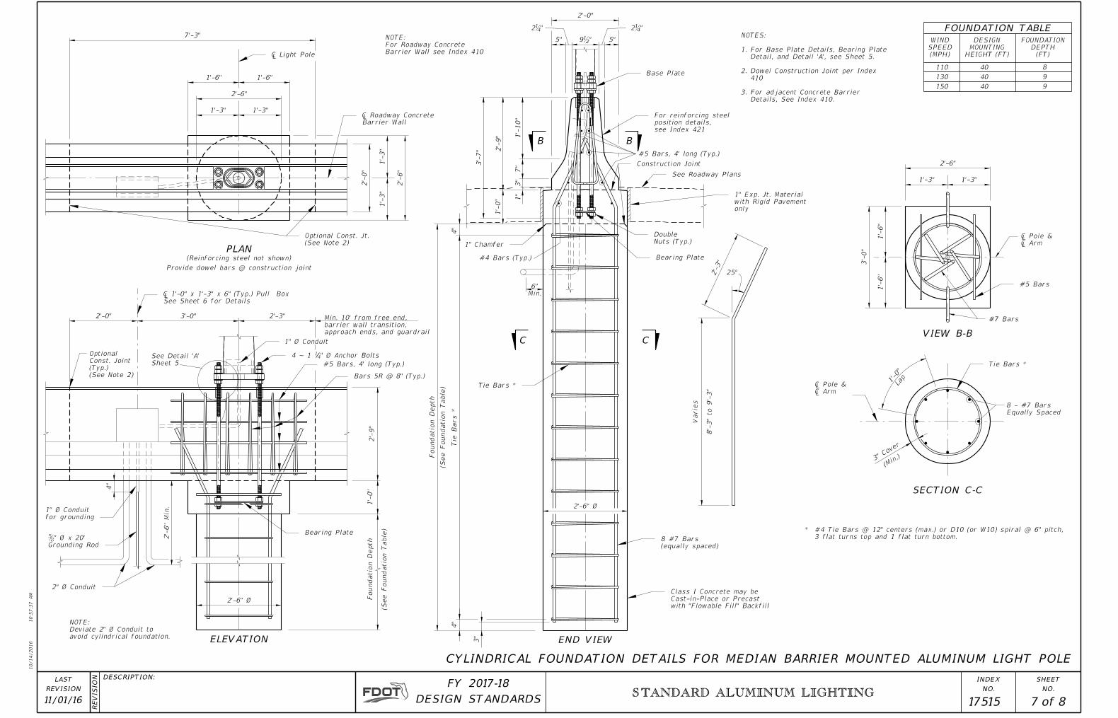
8
9
9
40
40
40
130
110
150
(MPH)
SPEED
WIND
HEIGHT (FT)
MOUNTING
DESIGN
(FT)
DEPTH
FOUNDATION
#5 Bars, 4' long (Typ.)
#4 Bars (Typ.)
avoid cylindrical foundation.
Deviate 2" Ø Conduit to
NOTE:
STANDARD ALUMINUM LIGHTING
11/01/16 17515 7 8
� Arm � Pole &
Tie Bars *
3" C
over
(Min.)
(See Foundatio
n Table)
Foundatio
n
Depth
(See Foundatio
n Table)
Foundatio
n
Depth
Tie Bars *
Base Plate
Construction Joint
See Roadway Plans
only
with Rigid Pavement
1" Exp. Jt. Material
Nuts (Typ.)
Double
Bearing Plate
Tie Bars *
(equally spaced)
8 #7 Bars
with "Flowable Fill" Backfill
Cast-in-Place or Precast
Class I Concrete may be
1" Chamfer
3"
4"
4"
Barrier Wall
� Roadway Concrete
1" Ø Conduit
" Ø Anchor Bolts414 ~ 1
#5 Bars, 4' long (Typ.)
Bars 5R @ 8" (Typ.)
Bearing Plate
for grounding
1" Ø Conduit
2" Ø Conduit
3 flat turns top and 1 flat turn bottom.
* #4 Tie Bars @ 12" centers (max.) or D10 (or W10) spiral @ 6" pitch,
Grounding Rod
ƅ" Ø x 20'
See Sheet 6 for Details
� 1'-0" x 1'-3" x 6" (Typ.) Pull Box
� Light Pole
#5 Bars
(See Note 2)
Optional Const. Jt.
see Index 421
position details,
For reinforcing steel
(See Note 2)
(Typ.)
Const. Joint
Optional
Details, See Index 410.
3. For adjacent Concrete Barrier
410
2. Dowel Construction Joint per Index
Detail, and Detail 'A', see Sheet 5.
1. For Base Plate Details, Bearing Plate
NOTES:
Lap
1'-0"
Equally Spaced
8 - #7 Bars
2'-6"
1'-3"1'-3"
3'-
0"
1'-
6"
1'-
6"
#7 Bars
� Arm � Pole &
8'-
3" to 9'-
3"
Varie
s
25°2'-3"
1'-
0"
Min.
6"
1'-
0" 1"
3"
7"
1'-
10"
2'-
9"
3'-
7"
5"5"
2'-0"
7'-3"
1'-6" 1'-6"
2'-6"
1'-3"1'-3"
2'-
0"
1'-
3"
1'-
3"
2'-
6"
(Reinforcing steel not shown)
Provide dowel bars @ construction joint
2'-3"3'-0"2'-0"
2'-
6"
Min.
4"
Sheet 5
See Detail 'A'
VIEW B-B
SECTION C-C
CC
BB
END VIEWELEVATION
PLAN
FOUNDATION TABLE
CYLINDRICAL FOUNDATION DETAILS FOR MEDIAN BARRIER MOUNTED ALUMINUM LIGHT POLE
2'-6" Ø
2'-6" Ø
2Ɓ" 2Ɓ"
9ƀ"
Barrier Wall see Index 410
For Roadway Concrete
NOTE:
approach ends, and guardrail
barrier wall transition,
Min. 10' from free end,
2'-
9"

10/14/2016
10:5
7:3
9
AM
RE
VISIO
N
NO.
SHEET
NO.
INDEXDESCRIPTION:
REVISION
LAST
of DESIGN STANDARDS
FY 2017-18
Bars 5S (Typ.)
54°30'
ØBØA
5ƀ" (Typ.)
STANDARD ALUMINUM LIGHTING
11/01/16 17515 8 8
Bridge Deck
Bridge Deck Optional Const. Jt.
about � Light PoleSymmetrical
� Traffic Railing (Median 32" F Shape)
Bearing Plate
Bars 5S 2" Ø Conduit
Bars 5R (Typ.)
Bars 5W (Typ.)
2" Ø Conduit
1" Ø Conduit
� 1'-0" x 1'-3" x 8" (Max.) Pull Box
Bridge DeckBars 5W
Construction Joint
Bars 5R
Bearing Plate
Base Plate
Bridge Deck
1" Ø Conduit
Min.
8"
4 ~ 1Ɓ" Ø Anchor Bolts
Anchor Bolts
For Bars and
6" Min. Embedment
and for angles �A and �B.See Index 421 for details of adjacent Traffic Railing (Median 32" F-Shape) 2.
For Base Plate Details, Bearing Plate Details, and Detail 'A', see Sheet 5.1.
NOTES:
position, see Index 421
For reinforcing steel
5"5"
2'-0"
1'-
10"
7"
3"
2'-
8"
3'-
2"
Min.
(Longitudinal and transverse deck reinforcing steel not shown)
7'-3"
2'-
0"
2'-0" 3'-0" 2'-3"
Bars 5R and 5W @ 1'-0"Bars 5R and 5W @ 8"±Bars 5R and 5W @ 1'-0"
Sheet 5
See Detail 'A'
Traffic Railin
g
2'-
8"
Cover
2"
(Longitudinal and transverse deck reinforcing steel not shown)
(Reinforcing steel not shown)
Min. 5' from � open joint
PLAN
ELEVATION
END VIEW
DETAILS FOR TRAFFIC RAILING (MEDIAN 32" F-SHAPE) MOUNTED ALUMINUM LIGHT POLE
Deck
Min.
8"
7Ɓ" 7Ɓ"
2Ɓ"
2Ɓ"
2Ɓ" 2Ɓ"
9ƀ"
Anchor B
olt E
mbed
ment
Depth
BAR BENDING DIAGRAMS
3"3"
2'-
5"
9"
1'-2"
BARS 5WBARS 5R
9Ƃ"
3Ƃ"
1'-4ƀ"
(See Note 2)