Embed Size (px)
Citation preview
International Journal of Science and Research (IJSR) ISSN (Online): 2319-7064
Index Copernicus Value (2013): 6.14 | Impact Factor (2013): 4.438
Volume 4 Issue 4, April 2015
www.ijsr.net Licensed Under Creative Commons Attribution CC BY
Design and Analysis of Composite Drive Shaft
Pankaj K. Hatwar1, Dr. R.S. Dalu
2
1 Government College of Engineering, Mechanical Engineering Department, Amravati, India
Abstract: Polymeric materials reinforced with synthetic fibres such as glass, carbon, and aramid provide advantages of high stiffness
and strength to weight ratio as compared to conventional construction materials, i.e. wood, concrete, and steel. Despite these
advantages, the widespread use of synthetic fibre-reinforced polymer composite has a tendency to decline because of their high-initial
costs, their use in non-efficient structural forms and most importantly their adverse environmental impact. In the recent days, there is a
huge demand for a light weight material such as fiber reinforced polymer composites seems to be a promising solution to this arising
demand. These materials have gained attention due to their applications in the field of automotive, aerospace, sports goods, medicines
and household appliances. The overall objective of this work is to analyze a composite drive shaft for power transmission. This work
deals with the replacement of conventional steel drive shafts composite drive shaft for an automotive application.
Keywords: automotive, composite, cost, drive shaft, fibre
1. Introduction
A driveshaft is a rotating shaft that transmits power from the
engine to the differential gear of a rear wheel drive vehicles.
Driveshaft must operate through constantly changing angles
between the transmission and axle. The drive shaft should
provide a smooth, uninterrupted flow of power to the axles.
High quality steel is a common material for construction.
Composites have already proven their worth as weight-saving
materials, the current challenge is to make them cost
effective. Definition stated by Jartiz “Composites are
multifunctional material systems that provide characteristics
not obtainable from any discrete material. They are cohesive
structures made by physically combining two or more
compatible materials, different in composition and
characteristics and sometimes in form”. . They have high
specific modulus and strength, reduced weights. Due to the
weight reduction, fuel consumption will be reduced. They
have high damping capacity hence they produce less
vibration and noise. They have good corrosion resistance.
Greater torque capacities than steel or aluminum shaft. The
fundamental natural frequency of the carbon fiber composite
drive shaft can be twice as high as that of steel or aluminum
because the carbon fiber composite material has more than 4
times the specific stiffness of steel or aluminum, which
makes it possible to manufacture the drive shaft of passenger
cars in one piece.
There are varieties of commercial FEA software available
over the market. Development of the finite element method
closely parallels the timetable of the Development of the
digital computer. Prior to the advent of the digital computer,
work during the 1940’s involved the approximation of
continuous solids as a collection of line elements (bars and
beams). However, due to the lack of computation tools, the
number of line elements had to be kept to a minimum. The
first appearance of two-dimensional elements appeared in a
paper published in 1956 by Turner, Clough, Martin, and Top
[1]. Some of the popular commercially available FEA
software are as follows. • Adina • Abaqus • Ansys •
MSC/Nastran • Cosmos • NISA • Marc • Ls-Dyna •
MSC/Dytran • Star-CD.
ANSYS is a general-purpose finite element-modeling
package for numerically solving a wide variety of mechanical
problems. It enables engineers to perform the following tasks
- build computer models or transfer cad models of structures,
products, components or system, apply operating loads or
other design performance conditions, study physical
responses such as stress levels, temperature distributions or
electromagnetic fields, optimize a design early in the
development process to reduce production costs, carryout
prototype testing in environment where it otherwise would be
undesirable or impossible. ANSYS provides a cost-effective
way to explore the performance of products or processes in a
virtual environment. This type of product development is
termed virtual prototyping. With virtual prototyping
techniques, users can iterate various scenarios to optimize the
product life before the manufacturing is started. This enables
a reduction in the level of risk, and in the cost of ineffective
designs. The multifaceted nature of ANSYS also provides a
means to ensure that users are able to see the effect of design
on the whole behavior of the product, be it electromagnetic,
thermal, mechanical etc.
2. Literature Survey
D.G. Lee [2] manufacture Drive Shaft using Carbon/Epoxy
composite with aluminum and find performance of Drive
Shaft.
Bhirud Pankaj Prakash [3] Design and Analysis Composite
Drive Shaft for Automotive by using E glass polyester
resin with ansis to find deformation.
Sagar R dharmadhikari [4] Design and Analysis Composite
Drive Shaft for Automotive by using Carbon/Epoxy and
genetic algorithm.
M.R. Khoshravan [3] Design a Composite Drive Shaft and
its Coupling for Automotive Application using HM
carbon/epoxy.
R. P. Kumar Rompicharla [6] Design and Optimization of
Drive Shaft with Composite Materials. The drive shaft of
Toyota Qualis was chosen for determining the dimensions.
D.dinesh [7] done Optimum Design and Analysis of a
Composite Drive Shaft for an Automobile by Using
Genetic Algorithm and Ansys using Carbon/Epoxy.
Paper ID: SUB153516 1955

International Journal of Science and Research (IJSR) ISSN (Online): 2319-7064
Index Copernicus Value (2013): 6.14 | Impact Factor (2013): 4.438
Volume 4 Issue 4, April 2015
www.ijsr.net Licensed Under Creative Commons Attribution CC BY
Bhushan K. Suryawanshi Design and Analysis Composite
Drive Shaft for Automotive by using Carbon/Epoxy
composite with aluminum and find the static torque
capability and the fundamental natural frequency.
Harshal Bankar [9] done Material Optimization and
Weight Reduction of Drive Shaft Using Composite
Material Boron/epoxy.
M.A.K. Chowdhuri [10] done Design Analysis of an
Automotive Composite Drive Shaft Using Graphite/ Epoxy
and Aluminum.
V. S. Bhajantri [11], Arun Ravi [12] Design and Analysis
Composite Drive Shaft for Automotive by using
Carbon/Epoxy.
K.D Ghatage [13] done Optimum design of automotive
composite drive shaft with genetic algorithm as
optimization tool.
R. Srinivasa Moorthy [14] Design Automobile Driveshaft
using Carbon/Epoxy and Kevlar/Epoxy Composites.
Parshuram D [15] Design and Analysis Composite/Hybrid
Drive Shaft for Automotive. They uses Crowfoot satin
woven glass fiber epoxy, Carbon/Epoxy composite with
aluminum.
3. Selection of Material
3.1 Selection of Reinforcement Fiber
Fibers are available with widely differing properties. Review
of the design and performance requirements usually dictate
the fiber/fibers to be used. Carbon/Graphite fibers: Its
advantages include high specific strength and modulus, low
coefficient of thermal expansion, and high fatigue strength.
Graphite, when used alone has low impact resistance. Its
drawbacks include high cost, low impact resistance, and high
electrical conductivity. Glass fibers: Its advantages include
its low cost, high strength, high chemical resistance, and
good insulating properties. The disadvantages are low elastic
modulus, poor adhesion to polymers, low fatigue strength,
and high density, which increase shaft size and weight. Also
crack detection becomes difficult.
3.2 Selection of Resin System
The important considerations in selecting resin are cost,
temperature capability, elongation to failure and resistance to
impact (a function of modulus of elongation). The resins
selected for most of the drive shafts are either epoxies or
vinyl esters. Here, epoxy resin was selected due to its high
strength, good wetting of fibers, lower curing shrinkage, and
better dimensional stability.
Table 1: Material properties of steel (sm45) SN Mechanical properties Symbol Units Value
1 Young’s modulus E GPa 207.0
2 Shear modulus G GPa 80.0
3 Poisson’s ratio υ ---- 0.3
4 Density ρ Kg/m3 7600
5 Yield strength Sy MPa 370
6 Shear strength Sx MPa 275
Table 2: material properties of carbon/epoxy composite and
glass/epoxy composite SN Property Symbol Units Carbon/Ep
oxy
Glass/Ep
oxy
1 Longitudinal Modulus E11 GPa 190 50
2 Transverse Modulus E22 GPa 7.7 12
3 Shear Modulus G12 GPa 4.2 5.6
4 Poisson’s Ratio υ ----- 0.3 0.3
5 Density ρ Kg/m3 1600 2000
6 Longitudinal Tensile
strength
St1 Mpa 870 800
7 Transverse Tensile
strength
St2 Mpa 540 40
8 shear strength Ss Mpa 30 72
4. Design of Drive Shaft
4.1 Assumptions
1) The shaft rotates at a constant speed about its longitudinal
axis.
2) The shaft has a uniform, circular cross section.
3) The shaft is perfectly balanced, i.e., at every cross section,
the mass center coincides with the geometric center.
4) All damping and nonlinear effects are excluded.
5) The stress-strain relationship for composite material is
linear & elastic; hence, Hooke’s law is applicable for
composite materials.
6) Acoustical fluid interactions are neglected, i.e., the shaft is
assumed to be acting in a vacuum.
7) Since lamina is thin and no out-of-plane loads are applied,
it is considered as under the plane stress.
4.2 Selection of Cross-Section
The drive shaft can be solid circular or hollow circular. Here
hollow circular cross-section was chosen because:
The hollow circular shafts are stronger in per kg weight
than solid circular.
The stress distribution in case of solid shaft is zero at the
center and maximum at the outer surface while in hollow
shaft stress variation is smaller. In solid shafts the material
close to the center are not fully utilized.
Table 3: Specification of the drive shaft Sr.no. Name Notation Unit Value
1 Ultimate torque T Nm 3500
2 Max. speed of shaft N Rpm 6500
3 Length of shaft L mm 1250
4 Max. diameter of shaft do mm 100
5 Thickness of shaft t mm 3.32
4.3 Mass of Drive Shaft
m= ρAL
Where do = outer diameter (m)
di = inner diameter (m)
m = 8.58 Kg
Paper ID: SUB153516 1956
International Journal of Science and Research (IJSR) ISSN (Online): 2319-7064
Index Copernicus Value (2013): 6.14 | Impact Factor (2013): 4.438
Volume 4 Issue 4, April 2015
www.ijsr.net Licensed Under Creative Commons Attribution CC BY
4.4 Torque Transmition Capacity of Drive Shaft
Ss
Torsional Buckling Capacity of Drive Shaft
If
It is called as long shaft otherwise short and medium shaft
For long shaft critical stress is given by,
For short and medium shaft critical stress is given by,
The relation between tortional buckling capacity and critical
stress is given by,
or
4.5 Lateral or Bending Vibration
Bernoulli-euler beam theory – Ncrbe
fnbe
Where p=1, 2……
Ncrbe=60fnbe
Timoshenko’s beam theory-Ncrt
fnt
Ncrt=60fnt
Where fs=2 for hollow shaft
Table 4: Design Solution Torque transmition
capacity (Nm)
Torsional buckling
capacity (Nm)
Frequency
(rpm)
steel 43101.25 13361.84 9660
carbon/Epoxy 4701.93 3951.44 20160
Glass/Epoxy 11284.632 3947.55 9300
specification 3500(O.K) 3500(O.K) 6500(O.K)
5. Analysis of Drive Shaft Using Ansys
5.1 Modeling and simulation
In this section the 3D CAD models and 3D FE Models along
with the loads and boundary conditions will be presented.
Step1: 3D PROE Model Creation was done based on
considered Specifications and design consideration from
passenger car, small truck, van specifications.
Step2: 3D FE Model Creation The 3D FE model for drive
shaft was created by using FE modeling software. The mesh
has been generated using relevance as 10 in ANSYS
workbench.
Step-3: using model with boundary conditions in ansys12.0
required results are predicted.
Step-4: By applying boundary conditions and loading
conditions obtained results will compared and suitable
material suggested which gives less torsional value and
frequency nearer to steel.
5.2 Static analysis
A static analysis is used to determine the displacements,
stresses, strains and forces in structures or components
caused by loads that do not induce significant inertia and
damping effects. A static analysis can however include steady
inertia loads such as gravity, spinning and time varying loads.
In static analysis loading and response conditions are
assumed, that is the loads and the structure responses are
assumed to vary slowly with respect to time. The kinds of
loading that can be applied in static analysis includes,
Externally applied forces, moments and pressures Steady
state inertial forces such as gravity and spinning Imposed
non-zero displacements. If the stress values obtained in this
analysis crosses the allowable values it will result in the
failure of the structure in the static condition itself. To avoid
such a failure, this analysis is necessary.
Boundary conditions
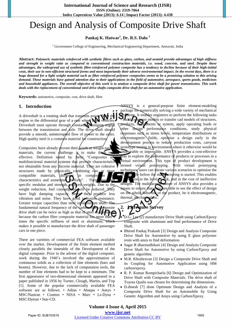
The finite element model of HS Carbon / Epoxy shaft is
shown in Figure .One end is fixed and torque is applied at
other end.
Figure 1: ANSYS Model with boundary conditions
5.3 Modal Analysis
When an elastic system free from external forces can
disturbed from its equilibrium position and vibrates under the
influence of inherent forces and is said to be in the state of
free vibration. It will vibrate at its natural frequency and its
amplitude will gradually become smaller with time due to
energy being dissipated by motion. The main parameters of
interest in free vibration are natural frequency and the
amplitude. The natural frequencies and the mode shapes are
important parameters in the design of a structure for dynamic
loading conditions. Modal analysis is used to determine the
vibration characteristics such as natural frequencies and
mode shapes of a structure or a machine component while it
is being designed. Most designs are sub critical, i.e.
rotational speed must be lower than the first natural bending
frequency of the shaft. The natural frequency depends on the
diameter of the shaft, thickness of the hollow shaft, specific
stiffness and the length.
Paper ID: SUB153516 1957
International Journal of Science and Research (IJSR) ISSN (Online): 2319-7064
Index Copernicus Value (2013): 6.14 | Impact Factor (2013): 4.438
Volume 4 Issue 4, April 2015
www.ijsr.net Licensed Under Creative Commons Attribution CC BY
5.4 Buckling Analysis
Buckling analysis is a technique used to determine buckling
loads (critical loads) at which a structure becomes unstable,
and buckled mode shapes. For thin walled shafts, the failure
mode under an applied torque is torsional buckling rather
than material failure. For a realistic driveshaft system,
improved lateral stability characteristics must be achieved
together with improved torque carrying capabilities.
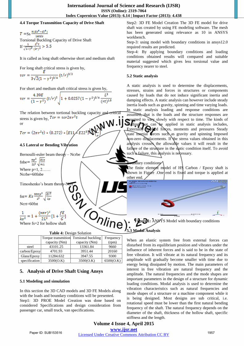
(a) (b)
(c)
Figure 2: Total deformation (a) Steel, (b) Glass/Epoxy
Composite, (c) Carbon/Epoxy Composite
(a) (b)
(c)
Figure 3: Equivalent (von-Mises) Stress (a) Steel, (b)
Glass/Epoxy Composite, (c) Carbon/Epoxy Composite
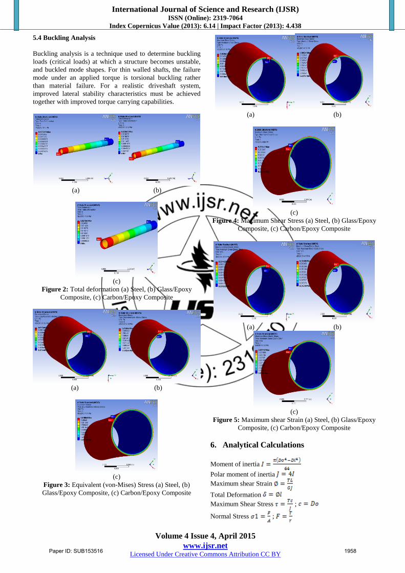
(a) (b)
(c)
Figure 4: Maximum Shear Stress (a) Steel, (b) Glass/Epoxy
Composite, (c) Carbon/Epoxy Composite
(a) (b)
(c)
Figure 5: Maximum shear Strain (a) Steel, (b) Glass/Epoxy
Composite, (c) Carbon/Epoxy Composite
6. Analytical Calculations
Moment of inertia
Polar moment of inertia
Maximum shear Strain
Total Deformation
Maximum Shear Stress ;
Normal Stress ;
Paper ID: SUB153516 1958
International Journal of Science and Research (IJSR) ISSN (Online): 2319-7064
Index Copernicus Value (2013): 6.14 | Impact Factor (2013): 4.438
Volume 4 Issue 4, April 2015
www.ijsr.net Licensed Under Creative Commons Attribution CC BY
Torsional Stress ;
Equivalent (von-Mises) Stress
Table 5: Validation and comparisons of analytical and ANSYS results Results Steel Carbon Glass
Ansys Analytical Ansys Analytical Ansys Analytical
Total Deformation(m) 0.0015 0.0025 0.027 0.048 0.021 0.036
Maximum shear Strain(m/m) 0.0012 0.0021 0.022 0.038 0.017 0.029
Maximum Shear Stress(MPa) 93 92.65 93 92.65 93 92.65
Equivalent (von-Mises) Stress(Pa) 161.1 160.6 161.1 160.6 161.1 160.6
Natural frequency (Hz) 166 161 385 336 160 155
Mass(Kg) 8.5888 8.5888 1.808 1.808 2.26 2.26
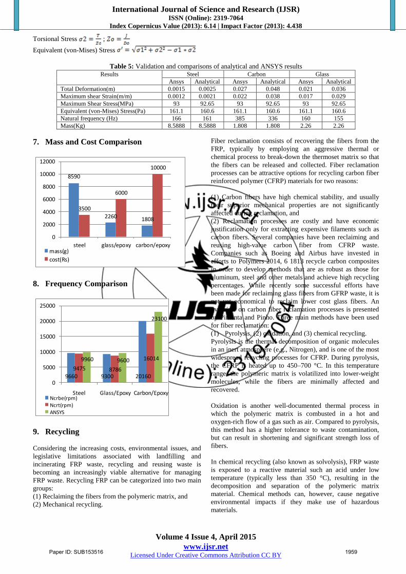
7. Mass and Cost Comparison
8590
2260 1808
3500
6000
10000
0
2000
4000
6000
8000
10000
12000
steel glass/epoxy carbon/epoxymass(g)
cost(Rs)
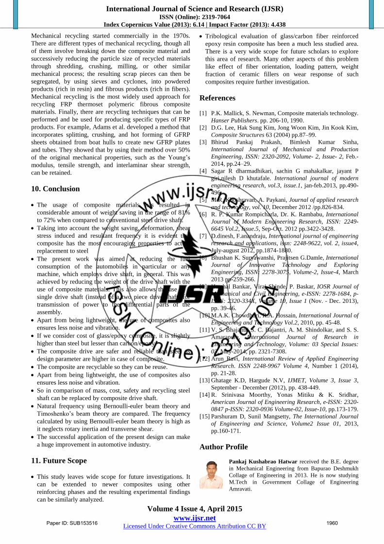
8. Frequency Comparison
9660 9300 20160
9475 8786
160149960 9600
23100
0
5000
10000
15000
20000
25000
Steel Glass/Epoxy Carbon/EpoxyNcrbe(rpm)
Ncrt(rpm)
ANSYS
9. Recycling
Considering the increasing costs, environmental issues, and
legislative limitations associated with landfilling and
incinerating FRP waste, recycling and reusing waste is
becoming an increasingly viable alternative for managing
FRP waste. Recycling FRP can be categorized into two main
groups:
(1) Reclaiming the fibers from the polymeric matrix, and
(2) Mechanical recycling.
Fiber reclamation consists of recovering the fibers from the
FRP, typically by employing an aggressive thermal or
chemical process to break-down the thermoset matrix so that
the fibers can be released and collected. Fiber reclamation
processes can be attractive options for recycling carbon fiber
reinforced polymer (CFRP) materials for two reasons:
(1) Carbon fibers have high chemical stability, and usually
their superior mechanical properties are not significantly
affected during reclamation, and
(2) Reclamation processes are costly and have economic
justification only for extracting expensive filaments such as
carbon fibers. Several companies have been reclaiming and
reusing high-value carbon fiber from CFRP waste.
Companies such as Boeing and Airbus have invested in
efforts to Polymers 2014, 6 1813 recycle carbon composites
in order to develop methods that are as robust as those for
aluminum, steel and other metals and achieve high recycling
percentages. While recently some successful efforts have
been made for reclaiming glass fibers from GFRP waste, it is
not yet economical to reclaim lower cost glass fibers. An
overview on carbon fiber reclamation processes is presented
by Pimenta and Pinho. Three main methods have been used
for fiber reclamation:
(1) Pyrolysis, (2) oxidation, and (3) chemical recycling.
Pyrolysis is the thermal decomposition of organic molecules
in an inert atmosphere (e.g., Nitrogen), and is one of the most
widespread recycling processes for CFRP. During pyrolysis,
the CFRP is heated up to 450–700 °C. In this temperature
range, the polymeric matrix is volatilized into lower-weight
molecules, while the fibers are minimally affected and
recovered.
Oxidation is another well-documented thermal process in
which the polymeric matrix is combusted in a hot and
oxygen-rich flow of a gas such as air. Compared to pyrolysis,
this method has a higher tolerance to waste contamination,
but can result in shortening and significant strength loss of
fibers.
In chemical recycling (also known as solvolysis), FRP waste
is exposed to a reactive material such an acid under low
temperature (typically less than 350 °C), resulting in the
decomposition and separation of the polymeric matrix
material. Chemical methods can, however, cause negative
environmental impacts if they make use of hazardous
materials.
Paper ID: SUB153516 1959
International Journal of Science and Research (IJSR) ISSN (Online): 2319-7064
Index Copernicus Value (2013): 6.14 | Impact Factor (2013): 4.438
Volume 4 Issue 4, April 2015
www.ijsr.net Licensed Under Creative Commons Attribution CC BY
Mechanical recycling started commercially in the 1970s.
There are different types of mechanical recycling, though all
of them involve breaking down the composite material and
successively reducing the particle size of recycled materials
through shredding, crushing, milling, or other similar
mechanical process; the resulting scrap pieces can then be
segregated, by using sieves and cyclones, into powdered
products (rich in resin) and fibrous products (rich in fibers).
Mechanical recycling is the most widely used approach for
recycling FRP thermoset polymeric fibrous composite
materials. Finally, there are recycling techniques that can be
performed and be used for producing specific types of FRP
products. For example, Adams et al. developed a method that
incorporates splitting, crushing, and hot forming of GFRP
sheets obtained from boat hulls to create new GFRP plates
and tubes. They showed that by using their method over 50%
of the original mechanical properties, such as the Young’s
modulus, tensile strength, and interlaminar shear strength,
can be retained.
10. Conclusion
The usage of composite materials has resulted in
considerable amount of weight saving in the range of 81%
to 72% when compared to conventional steel drive shaft.
Taking into account the weight saving, deformation, shear
stress induced and resultant frequency it is evident that
composite has the most encouraging properties to act as
replacement to steel
The present work was aimed at reducing the fuel
consumption of the automobiles in particular or any
machine, which employs drive shaft, in general. This was
achieved by reducing the weight of the drive shaft with the
use of composite materials. This also allows the use of a
single drive shaft (instead of a two piece drive shaft) for
transmission of power to the differential parts of the
assembly.
Apart from being lightweight, the use of composites also
ensures less noise and vibration.
If we consider cost of glass/epoxy composite, it is slightly
higher than steel but lesser than carbon/epoxy.
The composite drive are safer and reliable than steel as
design parameter are higher in case of composite.
The composite are recyclable so they can be reuse.
Apart from being lightweight, the use of composites also
ensures less noise and vibration.
So in comparison of mass, cost, safety and recycling steel
shaft can be replaced by composite drive shaft.
Natural frequency using Bernoulli-euler beam theory and
Timoshenko’s beam theory are compared. The frequency
calculated by using Bernoulli-euler beam theory is high as
it neglects rotary inertia and transverse shear.
The successful application of the present design can make
a huge improvement in automotive industry.
11. Future Scope
This study leaves wide scope for future investigations. It
can be extended to newer composites using other
reinforcing phases and the resulting experimental findings
can be similarly analyzed.
Tribological evaluation of glass/carbon fiber reinforced
epoxy resin composite has been a much less studied area.
There is a very wide scope for future scholars to explore
this area of research. Many other aspects of this problem
like effect of fiber orientation, loading pattern, weight
fraction of ceramic fillers on wear response of such
composites require further investigation.
References
[1] P.K. Mallick, S. Newman, Composite materials technology.
Hanser Publishers. pp. 206-10, 1990.
[2] D.G. Lee, Hak Sung Kim, Jong Woon Kim, Jin Kook Kim,
Composite Structures 63 (2004) pp.87–99.
[3] Bhirud Pankaj Prakash, Bimlesh Kumar Sinha,
International Journal of Mechanical and Production
Engineering, ISSN: 2320-2092, Volume- 2, Issue- 2, Feb.-
2014, pp.24–29.
[4] Sagar R dharmadhikari, sachin G mahakalkar, jayant P
giri,nilesh D khutafale. International journal of modern
engineering research, vol.3, issue.1, jan-feb.2013, pp.490-
496.
[5] M.R. Khoshravan, A. Paykani, Journal of applied research
and technology, vol. 10, December 2012 /pp.826‐834.
[6] R. P. Kumar Rompicharla, Dr. K. Rambabu, International
Journal of Modern Engineering Research, ISSN: 2249-
6645 Vol.2, Issue.5, Sep-Oct. 2012 pp.3422-3428.
[7] D.dinesh, F.anandraju, International journal of engineering
research and applications, issn: 2248-9622, vol. 2, issue4,
July-august 2012, pp.1874-1880.
[8] Bhushan K. Suryawanshi, Prajitsen G.Damle, International
Journal of Innovative Technology and Exploring
Engineering, ISSN: 2278-3075, Volume-2, Issue-4, March
2013 pp-259-266.
[9] Harshal Bankar, Viraj Shinde, P. Baskar, IOSR Journal of
Mechanical and Civil Engineering, e-ISSN: 2278-1684, p-
ISSN: 2320-334X, Volume 10, Issue 1 (Nov. - Dec. 2013),
pp. 39-46.
[10] M.A.K. Chowdhuri, R.A. Hossain, International Journal of
Engineering and Technology Vol.2, 2010, pp. 45-48.
[11] V. S. Bhajantri S. C. Bajantri, A. M. Shindolkar, and S. S.
Amarapure, International Journal of Research in
Engineering and Technology, Volume: 03 Special Issues:
03, May-2014, pp. 2321-7308.
[12] Arun Ravi, International Review of Applied Engineering
Research. ISSN 2248-9967 Volume 4, Number 1 (2014),
pp. 21-28.
[13] Ghatage K.D, Hargude N.V, IJMET, Volume 3, Issue 3,
September - December (2012), pp. 438-449.
[14] R. Srinivasa Moorthy, Yonas Mitiku & K. Sridhar,
American Journal of Engineering Research, e-ISSN: 2320-
0847 p-ISSN: 2320-0936 Volume-02, Issue-10, pp.173-179.
[15] Parshuram D, Sunil Mangsetty, The International Journal
of Engineering and Science, Volume2 Issue 01, 2013,
pp.160-171.
Author Profile
Pankaj Kushabrao Hatwar received the B.E. degree
in Mechanical Engineering from Bapurao Deshmukh
Collage of Engineering in 2013. He is now studying
M.Tech in Government Collage of Engineering
Amravati.
Paper ID: SUB153516 1960