Embed Size (px)
Citation preview
Fuzzy Logic Controller For An Autonomous Mobile Robot
NAFIPS June 24, 2005
Vamsi Mohan Peri Dr. Dan Simon

Outline
IntroductionDesign of the RobotFuzzy Logic ControllerHardware DescriptionSoftware DescriptionResultsApplicationsConclusions
Introduction
Maintaining a fixed path on the course in order to keep the robot from getting lost.
It should be totally autonomous, shouldn’t transmit or receive signals.

Design of the Robot

Types of Robotic Behavior
Goal directed
navigation
Goal seek RouteFollow
Go to X-Y Avoid collision Wall follow Doorway/
Corridor
Components of the Robot
Two wheels driven by servo motors.
Translatory wheel for stability.
Ultrasonic sensors to measure distances.
PIC16F877 microcontroller.

Mathematical Model
, = angular velocities of wheels
, = linear velocities of wheels
r = nominal radius of each wheelL = distance between the two wheels
( )rw t ( )lw t
( )rv t ( )lv t

( ) ( ) c o s ( )( ) ( ) s i n ( )( ) ( )
x t v t ty t v t tt w t
θθ
θ
==
=
1( ) ( ) ( ( ) ( ))2 r lv t w t R w t w t= = +
1 1cos cos2 2( )1 1( ) sin sin2 2
( ) 1/ 1/
xr
yl
v tv
v tv
t L L
θ θ
θ θ
θ
= −
System equations:
Linear Velocity:
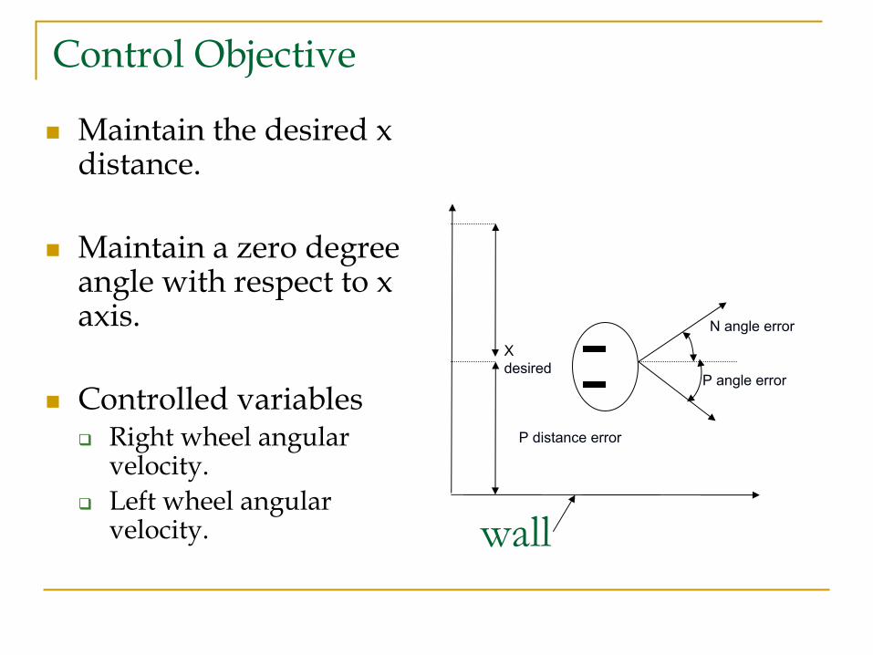
Control Objective
Maintain the desired x distance.
Maintain a zero degree angle with respect to x axis.
Controlled variablesRight wheel angular velocity.Left wheel angular velocity.
N angle error
P angle error
P distance error
X desired
wall
Fuzzy Logic Controller

Block Diagram of the System
Two inputs are error in angle of orientation and error in distance x.
The outputs of the controller would be pulse-width-modulated signals to control the angular velocity of the two servo wheels.
θ
Fuzzy LogicController
RobotSensor
Readings
, xθ
te xe
lw rw
Calculation of andte xe

Universe of Discourse
The range of error in angle is -0.3 to +0.3 radians.
The range of error in distance is -4 to 4 inches.
The angular velocities of the two wheels and range from -3 to 3 radians per second.
te
xe
lw rw
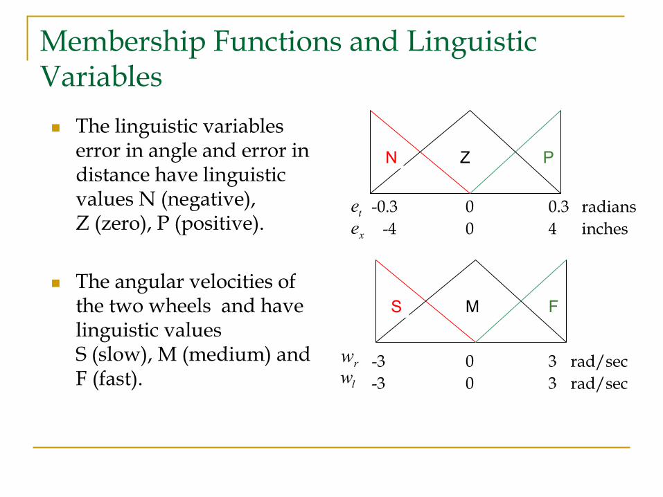
Membership Functions and Linguistic Variables
The linguistic variables error in angle and error in distance have linguistic values N (negative), Z (zero), P (positive).
The angular velocities of the two wheels and have linguistic values S (slow), M (medium) and F (fast).
N Z P
-0.3 0 0.3-4 0 4
radiansinches
-3 0 3-3 0 3
rad/sec
S M F
rad/sec
texe
rwlw
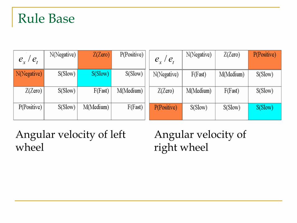
Rule Base
Angular velocity of left wheel
Angular velocity of right wheel
tx ee / tx ee /

Types of Membership Functions UsedSum Normal Membership Functions.
Easier to implement.Less computational effort.
Non Sum Normal Membership Functions.
More versatile.Computationally complex.
0
1
0
1

Hardware Description

Servo MotorsUltrasonic Sensors
PIC16F877 Microcontroller

Servo Motor
0.15 second speed through 60° revolution.
Strong 44 oz-in operation at 4.8 V .
Weighs only 1.66 oz.
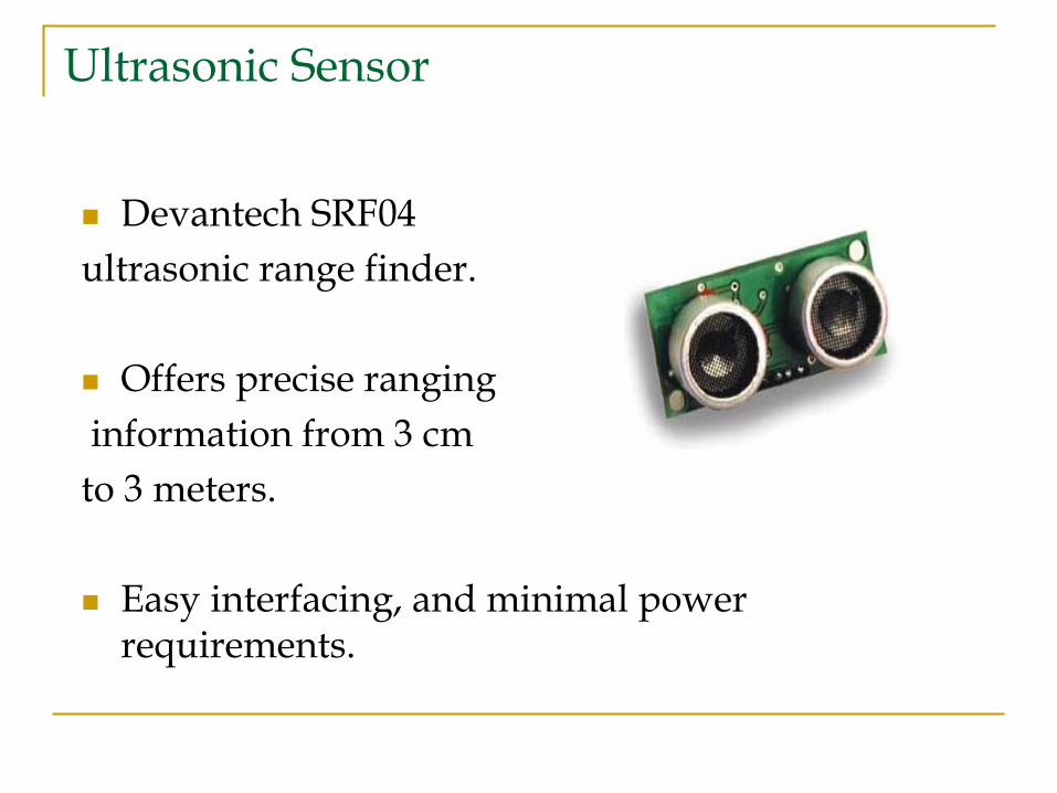
Ultrasonic Sensor
Devantech SRF04 ultrasonic range finder.
Offers precise ranginginformation from 3 cm to 3 meters.
Easy interfacing, and minimal power requirements.
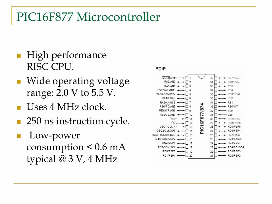
PIC16F877 Microcontroller
High performance RISC CPU.Wide operating voltage range: 2.0 V to 5.5 V.Uses 4 MHz clock.250 ns instruction cycle.Low-power
consumption < 0.6 mAtypical @ 3 V, 4 MHz

Software Description
The mobile robot was first simulated in SIMULINK.
Fuzzy logic toolbox was used initially.
Next M-files were written to simulate the whole system.
The microcontroller was programmed using a CCS C-compiler with debugger.
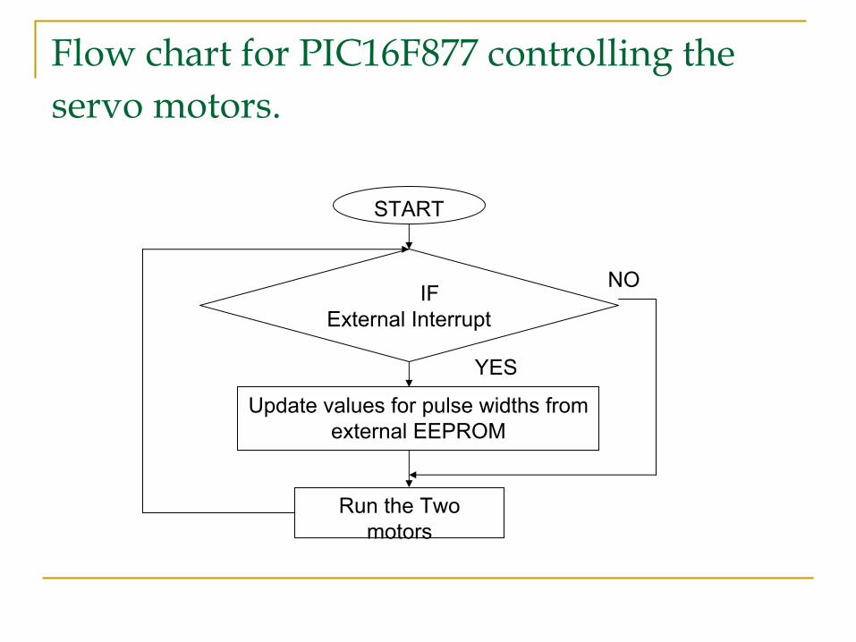
Flow chart for PIC16F877 controlling the servo motors.
Update values for pulse widths from external EEPROM
START
Run the Two motors
IF External Interrupt
YES
NO
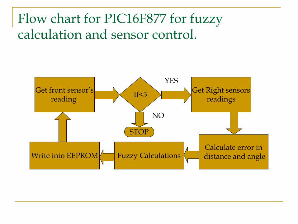
Flow chart for PIC16F877 for fuzzy calculation and sensor control.
Get front sensor’sreading
Get Right sensorsreadingsIf<5
Calculate error indistance and angleFuzzy CalculationsWrite into EEPROM
STOP
NO
YES
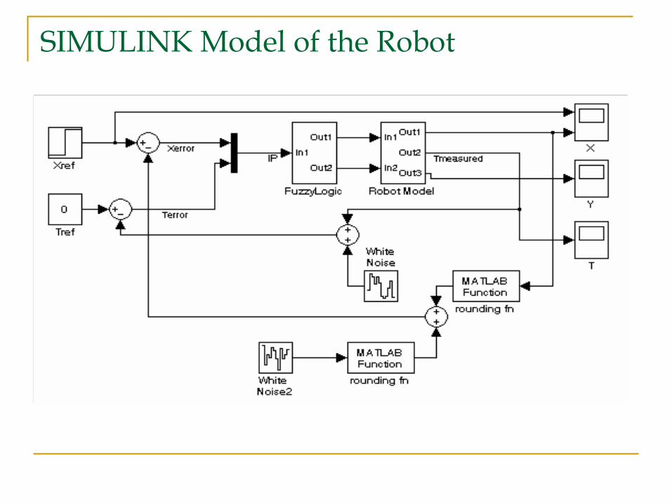
SIMULINK Model of the Robot

Results
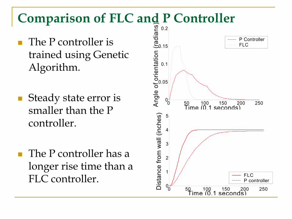
Comparison of FLC and P Controller
The P controller is trained using Genetic Algorithm.
Steady state error is smaller than the P controller.
The P controller has a longer rise time than a FLC controller.
0 50 100 150 200 2500
1
2
3
4
5
Time (0.1 seconds)
Dis
tanc
e fro
m w
all (
inch
es)
FLCP controller
0 50 100 150 200 2500
0.05
0.1
0.15
0.2
Time (0.1 seconds)Ang
le o
f orie
ntat
ion
(radi
ans)
P ControllerFLC
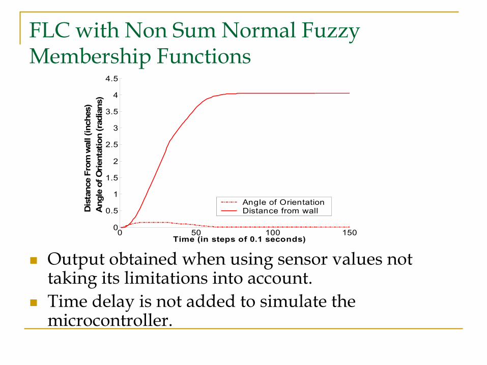
FLC with Non Sum Normal Fuzzy Membership Functions
Output obtained when using sensor values not taking its limitations into account.Time delay is not added to simulate the microcontroller.
0 50 100 1500
0.5
1
1.5
2
2.5
3
3.5
4
4.5
Time (in steps of 0.1 seconds)
Dis
tanc
e Fr
om w
all (
inch
es)
A
ngle
of O
rient
atio
n (r
adia
ns)
Angle of OrientationDistance from wall
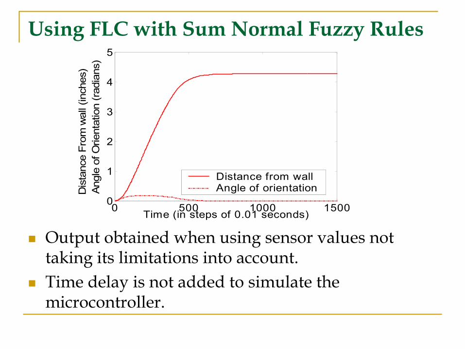
Using FLC with Sum Normal Fuzzy Rules
Output obtained when using sensor values not taking its limitations into account.Time delay is not added to simulate the microcontroller.
0 500 1000 15000
1
2
3
4
5
Time (in steps of 0.01 seconds)
Dis
tanc
e Fr
om w
all (
inch
es)
An
gle
of O
rient
atio
n (r
adia
ns)
Distance from wallAngle of orientation

Using FLC with Sum Normal Fuzzy Rules
The output from the sensors are rounded to the nearest inch.A delay of 360 milliseconds is added to simulate time delay in fuzzy calculations.
0 1000 2000 3000-1
0
1
2
3
4
5
Time (in steps of 0.01 seconds)
Dis
tanc
e Fr
om w
all (
inch
es)
An
gle
of O
rient
atio
n (r
adia
ns)
Distance from wallAngle of orientation

Comparison of P Controller, FLC with Sum Normal Membership Functions and FLC with Non Sum Normal Membership Functions
Applications
Agricultural applications.
Military applications.
Relief and rescue operations.
Remote navigation and exploration.
Conclusions
The highly nonlinear dynamic model of the mobile robot is developed.
Fuzzy logic controller was implemented in real time.
A traditional P controller and the fuzzy logic controller were compared and it was noticed that the fuzzy logic controller outperforms the P controller.

Thank You