Embed Size (px)
Citation preview
Fuzzy Logic 310LG RTC
User manual
Solid fuel boiler controller
with gutter burner ignition

2
On behalf of Pionier Elektryk, thank you for choosing the FL 310LG RTC controller. The FL 310LG RTL has
been designed and developed by a team of dedicated engineers. who have used their collective talents to
create a product that is efficient, user- friendly and safe to use. As a user of the FL 310LG RTL myself, I
sincerely recommend it to you and encourage you to read the following instructions. Also please visit our
website at www.pionier-elektryk.pl, where you can find professional help and valuable guidance with respect
to its installation and use.
Andrzej Kowalewski,
Founder, Pionier Elektryk
PIONIER ELEKTRYK
Andrzej Kowalewski
Zastawie I St. 17
Phone/Fax: 85 71 93 909
16-070 Choroszcz
www.pionier-elektryk.pl
3
1. TECHNICAL PARAMETERS
Table. 1.1. Technical parameters
Power ~230V/50Hz
Power consumption < 5VA
OPERATING COMPONENTS
C.O. pump 100W
C.W.U. pump 100W
Circulation pump 100W
Additional pump 100W
Blower 150W
Feeder 200W
Igniter 900W
Calorifier disinfection 100W
Motorised valve 50W
Lambda probe power supply 18W
WORKING TEMPERATURE RANGE:
Boiler temperature 55-80°C
C.W.U. temperature 5-80°C
Temperature tolerance +/-5°C
Temperature of boiler environment 2-55°C
Humidity range 5-95%
Boiler temperature alarm 90°C
Feeder temperature alarm 80°C
4
2. INTRODUCTION
The FL-310LG controller is an advanced microprocessor-based system designed to adjust the operating
parameters of solid fuel-powered boilers (i.e. pellet, grain, granulated coal, wood and the like). The
controller automatically calculates time of fuel supply which is suitable for existing conditions and the amount
of dispensed air necessary for proper combustion which significantly improves the ecological performance,
efficiency and economic operation of the boiler. The clock program provides a number of important and at
the same time innovative functions. These include the ability to set a weekly schedule of work for the
circulation and additional pump as well as the burner. Proper adjustment of these functions will increase the
usability of the boiler and contribute towards its efficiency.
The controller offers the user a choice of three automatic working modes which enable the central heating
and hot water supply to be adjusted to meet specific needs. This provides a significant convenience to the
user by eliminating the need to adjust the working parameters of the system as soon as conditions change
inside or outside the building.
A thermostatic room controller is also available as an optional extra which enables a constant temperature to
be maintained in the room or areas of the building most frequently used.
The measurement of exhaust gas temperature and the level of oxygen contained in exhaust gas emissions
enables a high level of boiler efficiency to be achieved. The lambda probe is the central element responsible
for the combustion process and in conjunction with other elements of the boiler helps to maximize the
effectiveness of its operation. This in turn leads to a reduction in boiler operating costs and cleaner exhaust
gas emissions.
The controller is equipped with a graphical LCD display which enables the user to change the value of
editable parameters and control other settings responsible for optimum operation of the boiler. This is an
intuitive program and the interface is easy to use even for a beginner with limited knowledge.
3. SYSTEM CONTROLS
The FL-310LG controller, controls and monitors the work of the boiler, which primarily requires to be
equipped with a feeder tray, fan and circulation pumps for both the central heating and hot water circuits(for
domestic use). In addition, it is strongly recommended to install an oxygen sensor (Lambda probe),
igniter and a valve actuator for the central heating system and a circulation pump.
For proper operation of the controller, sensors must be connected for measuring the temperature of:
Water in the hot water calorifier [CNT-125]
Outside air (for “Feather” based working mode) [CNT-125]
Exhaust gas [CPT-300]
Boiler heat exchanger [CNT-125]
Feeder tray mechanism [CNT-125]
WARNING!
The controller is manufactured from materials and includes components that are not
biodegradable and which may otherwise be considered hazardous. For safe disposal it should
either be returned to the manufacturer or given to a refuse collection agency specializing in the
recycling of non-biodegradable and hazardous waste. Under no circumstances should it be
discarded with municipal waste.

5
Fig. 3.1.1. General Arrangement Diagram
Fig. 3.1.2. General Arrangement Diagram Cont.
6
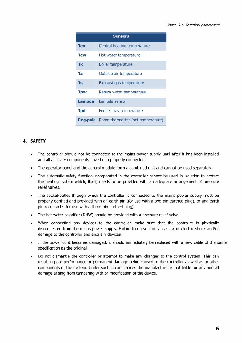
Table. 3.1. Technical parameters
Sensors
Tco Central heating temperature
Tcw Hot water temperature
Tk Boiler temperature
Tz Outside air temperature
Ts Exhaust gas temperature
Tpw Return water temperature
Lambda Lambda sensor
Tpd Feeder tray temperature
Reg.pok Room thermostat (set temperature)
4. SAFETY
The controller should not be connected to the mains power supply until after it has been installed
and all ancillary components have been properly connected.
The operator panel and the control module form a combined unit and cannot be used separately.
The automatic safety function incorporated in the controller cannot be used in isolation to protect
the heating system which, itself, needs to be provided with an adequate arrangement of pressure
relief valves.
The socket-outlet through which the controller is connected to the mains power supply must be
properly earthed and provided with an earth pin (for use with a two-pin earthed plug), or and earth
pin receptacle (for use with a three-pin earthed plug).
The hot water calorifier (DHW) should be provided with a pressure relief valve.
When connecting any devices to the controller, make sure that the controller is physically
disconnected from the mains power supply. Failure to do so can cause risk of electric shock and/or
damage to the controller and ancillary devices.
If the power cord becomes damaged, it should immediately be replaced with a new cable of the same
specification as the original.
Do not dismantle the controller or attempt to make any changes to the control system. This can
result in poor performance or permanent damage being caused to the controller as well as to other
components of the system. Under such circumstances the manufacturer is not liable for any and all
damage arising from tampering with or modification of the device.
7
5. ELECTRICAL INSTALLATION
When connecting the controller always observe statutory safety requirements. The control unit must only be
installed by a suitably qualified person or by an authorized installer and strictly in accordance with current
regulations, standards and codes of practice. The manufacturer is not liable for any damage arising from
breach of these instructions. The operating panel should be installed permanently in the outer boiler casing,
which will extend its life. The control module must also be protected against mechanical damage. This unit
should be connected to a mains electricity supply that features both an Earth Leakage Trip (ELT) and surge
protection.
The controller operates with CNT-125 sensors for temperatures ranging from -40°C to 125°C and CPT-300
sensors for temperatures ranging from -40°C to 350°C. Strap-on temperature sensors must be securely
fastened at the measuring points shown in this manual and provided with thermal insulation in order to
achieve the best possible accuracy of measurement.
5.1. Controller inputs
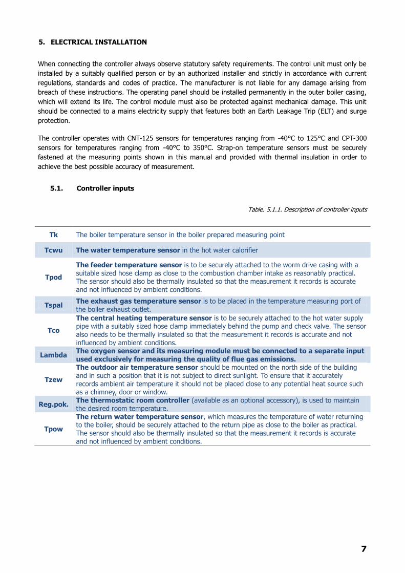
Table. 5.1.1. Description of controller inputs
Tk The boiler temperature sensor in the boiler prepared measuring point
Tcwu The water temperature sensor in the hot water calorifier
Tpod
The feeder temperature sensor is to be securely attached to the worm drive casing with a
suitable sized hose clamp as close to the combustion chamber intake as reasonably practical. The sensor should also be thermally insulated so that the measurement it records is accurate
and not influenced by ambient conditions.
Tspal The exhaust gas temperature sensor is to be placed in the temperature measuring port of
the boiler exhaust outlet.
Tco
The central heating temperature sensor is to be securely attached to the hot water supply pipe with a suitably sized hose clamp immediately behind the pump and check valve. The sensor
also needs to be thermally insulated so that the measurement it records is accurate and not
influenced by ambient conditions.
Lambda The oxygen sensor and its measuring module must be connected to a separate input
used exclusively for measuring the quality of flue gas emissions.
Tzew
The outdoor air temperature sensor should be mounted on the north side of the building
and in such a position that it is not subject to direct sunlight. To ensure that it accurately
records ambient air temperature it should not be placed close to any potential heat source such as a chimney, door or window.
Reg.pok. The thermostatic room controller (available as an optional accessory), is used to maintain the desired room temperature.
Tpow
The return water temperature sensor, which measures the temperature of water returning to the boiler, should be securely attached to the return pipe as close to the boiler as practical.
The sensor should also be thermally insulated so that the measurement it records is accurate
and not influenced by ambient conditions.
8
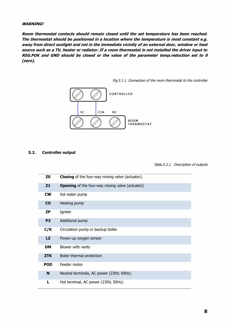
WARNING!
Room thermostat contacts should remain closed until the set temperature has been reached.
The thermostat should be positioned in a location where the temperature is most constant e.g.
away from direct sunlight and not in the immediate vicinity of an external door, window or heat
source such as a TV, heater or radiator. If a room thermostat is not installed the driver input to
REG.POK and GND should be closed or the value of the parameter temp.reduction set to 0
(zero).
Fig.5.1.1. Connection of the room thermostat to the controller
5.2. Controller output
Table.5.2.1. Description of outputs
Z0 Closing of the four-way mixing valve (actuator).
Z1 Opening of the four-way mixing valve (actuator)
CW hot water pump
CO Heating pump
ZP Igniter
P3 Additional pump
C/K Circulation pump or backup boiler
LZ Power-up oxygen sensor
DM Blower with vents
ZTK Boiler thermal protection
POD Feeder motor
N Neutral terminals, AC power (230V, 50Hz).
L Hot terminal, AC power (230V, 50Hz).
9
WARNING!
Connections must only be made while the controller is physically disconnected from the mains
power supply by a suitably qualified person or by an authorized installer.
6. DRIVER MENU
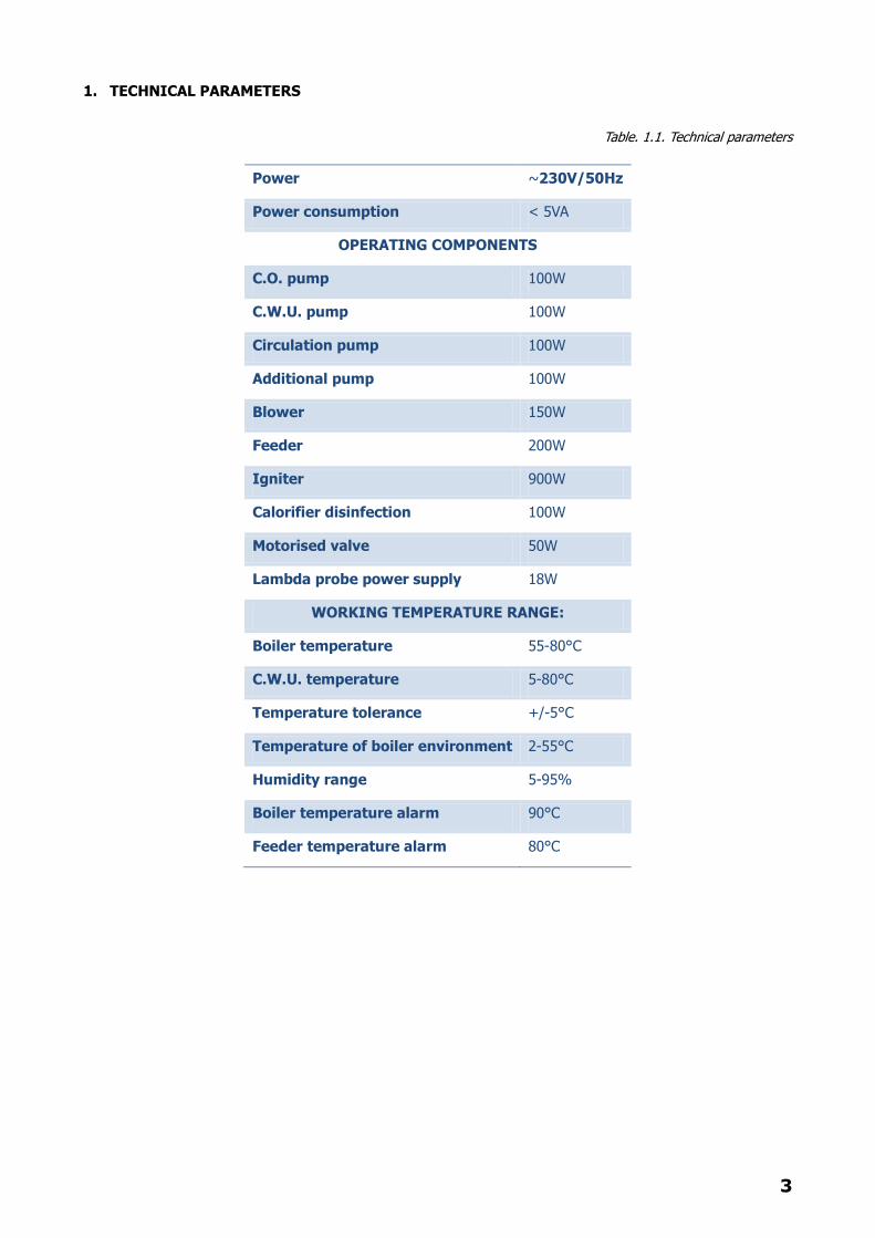
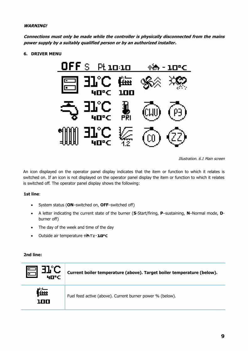
Illustration. 6.1 Main screen
An icon displayed on the operator panel display indicates that the item or function to which it relates is
switched on. If an icon is not displayed on the operator panel display the item or function to which it relates
is switched off. The operator panel display shows the following:
1st line:
System status (ON–switched on, OFF–switched off)
A letter indicating the current state of the burner (S-Start/firing, P–sustaining, N–Normal mode, D-
burner off)
The day of the week and time of the day
Outside air temperature
2nd line:
Current boiler temperature (above). Target boiler temperature (below).
Fuel feed active (above). Current burner power % (below).
10
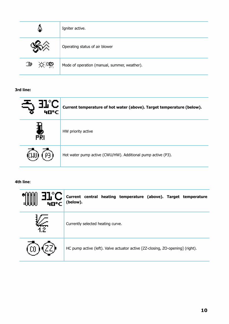
Igniter active.
Operating status of air blower
Mode of operation (manual, summer, weather).
3rd line:
Current temperature of hot water (above). Target temperature (below).
HW priority active
Hot water pump active (CWU/HW). Additional pump active (P3).
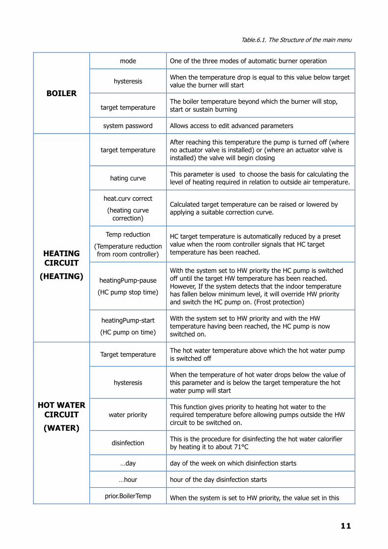
4th line:
Current central heating temperature (above). Target temperature
(below).
Currently selected heating curve.
HC pump active (left). Valve actuator active [ZZ-closing, ZO-opening] (right).
11
Table.6.1. The Structure of the main menu
BOILER
mode One of the three modes of automatic burner operation
hysteresis When the temperature drop is equal to this value below target value the burner will start
target temperature The boiler temperature beyond which the burner will stop,
start or sustain burning
system password Allows access to edit advanced parameters
HEATING CIRCUIT
(HEATING)
target temperature After reaching this temperature the pump is turned off (where no actuator valve is installed) or (where an actuator valve is
installed) the valve will begin closing
hating curve This parameter is used to choose the basis for calculating the level of heating required in relation to outside air temperature.
heat.curv correct
(heating curve
correction)
Calculated target temperature can be raised or lowered by applying a suitable correction curve.
Temp reduction
(Temperature reduction
from room controller)
HC target temperature is automatically reduced by a preset
value when the room controller signals that HC target
temperature has been reached.
heatingPump-pause
(HC pump stop time)
With the system set to HW priority the HC pump is switched off until the target HW temperature has been reached.
However, If the system detects that the indoor temperature has fallen below minimum level, it will override HW priority
and switch the HC pump on. (Frost protection)
heatingPump-start
(HC pump on time)
With the system set to HW priority and with the HW temperature having been reached, the HC pump is now
switched on.
HOT WATER CIRCUIT
(WATER)
Target temperature The hot water temperature above which the hot water pump
is switched off
hysteresis
When the temperature of hot water drops below the value of
this parameter and is below the target temperature the hot
water pump will start
water priority This function gives priority to heating hot water to the required temperature before allowing pumps outside the HW
circuit to be switched on.
disinfection This is the procedure for disinfecting the hot water calorifier by heating it to about 71°C
…day day of the week on which disinfection starts
…hour hour of the day disinfection starts
prior.BoilerTemp When the system is set to HW priority, the value set in this

12
(temperature as priority)
parameter will mean a temporary boiler temperature target.
BURNER
fuel Choice of fuel supply. One of the fuels defined in the menu.
support-STOP
waiting time between the boiler having reached its target
temperature and the switching on of the feeder tray in the sustain burning mode (applies only where EkoGroszek (pea
coal) is used as feedstock)
suport-STRT
Feeder tray working time in sustain burning mode after the
boiler reaches its target temperature. (applies only where pea coal is used as feedstock)
supp.BlowerAddit
(blower outlet)
The value of this parameter represents the time the blower is
working to sustain the heat in a measured amount of fuel between the time the boiler shuts down after reaching its
target temperature and start of the next heating cycle. (applies only where pea coal is used as feedstock)
antiblockade
(anti-lock)
When the boiler reaches its target temperature the feeder tray
is switched on every 20 minutes. The value of this parameter represents the period of time the feeder tray is active.
test mode power
When test mode is enabled, in order to establish certain
output parameters, the burner maintains a constant output
level equal to the value of this parameter
fuel trans.100%
(Administration at
100%)
Time of administration of a single dose of fuel at 100% power
of the burner. For the other powers of the burner, the feeder
working time is calculated by FuzzyLogic on the basis of this parameter
initial feeder
(initial application)
When the boiler reaches its target temperature, residual fuel
in the combustion chamber will be burned-off. When the burner starts up again after a fall in boiler temperature, it will
do so from an initial application of clean fuel. The feeder tray working time needed to provide that application is equal to the
value of this parameter)
inflamation
(fuel ignition)
After an initial amount of fuel, has been fed into the
combustion chamber the igniter switches on for a set period of time to raise the temperature in the fuel to a combustible
level. That time is set by this parameter. It is the time defined by this parameter that is used. Where an igniter is installed
with a power rating exceeding 600W, to avoid damage to the
igniter element the parameter must be set to a value of 0 (zero). Ignition will then be carried out using blower + igniter
igniter + blower
During firing mode the blower is used in conjunction with the
igniter. This enables proper ignition of the fuel to occur without risk of the igniter overheating
fire testing
(Trial Firing)
The burner attempts to start not by using the igniter but by
using the residual heat in the combustion chamber from a previous heating cycle. During this period the burner operates
in normal mode and attempts to stir up flame in conjunction with the blower.
13
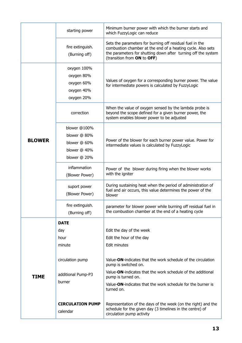
starting power Minimum burner power with which the burner starts and which FuzzyLogic can reduce
fire extinguish.
(Burning off)
Sets the parameters for burning off residual fuel in the
combustion chamber at the end of a heating cycle. Also sets
the parameters for shutting down after turning off the system (transition from ON to OFF)
BLOWER
oxygen 100%
oxygen 80%
oxygen 60%
oxygen 40%
oxygen 20%
Values of oxygen for a corresponding burner power. The value for intermediate powers is calculated by FuzzyLogic
correction
When the value of oxygen sensed by the lambda probe is
beyond the scope defined for a given burner power, the system enables blower power to be adjusted
blower @100%
blower @ 80%
blower @ 60%
blower @ 40%
blower @ 20%
Power of the blower for each burner power value. Power for
intermediate values is calculated by FuzzyLogic
inflammation
(Blower Power)
Power of the blower during firing when the blower works with the igniter
suport power
(Blower Power)
During sustaining heat when the period of administration of
fuel and air occurs, this value determines the power of the blower
fire extinguish.
(Burning off)
parameter for blower power while burning off residual fuel in
the combustion chamber at the end of a heating cycle
TIME
DATE
day
hour
minute
circulation pump
additional Pump-P3
burner
CIRCULATION PUMP
calendar
Edit the day of the week
Edit the hour of the day
Edit minutes
Value-ON-indicates that the work schedule of the circulation pump is switched on.
Value-ON-indicates that the work schedule of the additional pump is turned on.
Value-ON-indicates that the work schedule for the burner is
turned on.
Representation of the days of the week (on the right) and the schedule for the given day (3 timelines in the centre) of
circulation pump activity
14
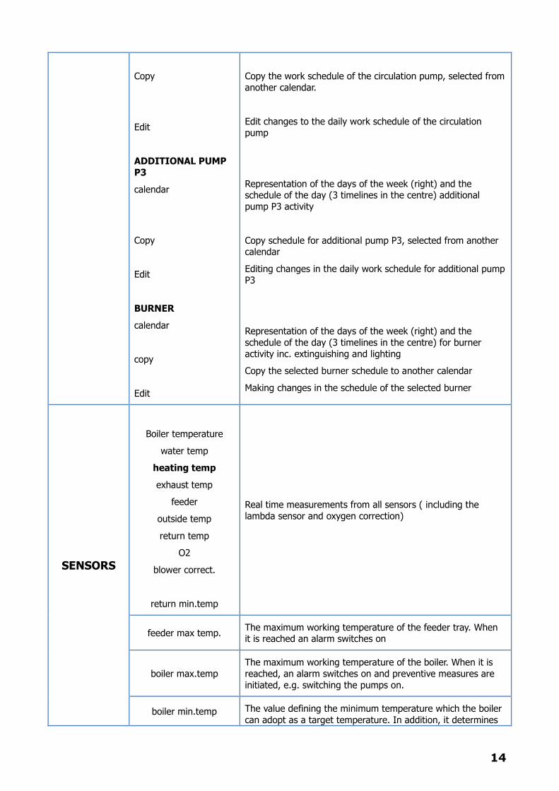
Copy
Edit
ADDITIONAL PUMP
P3
calendar
Copy
Edit
BURNER
calendar
copy
Edit
Copy the work schedule of the circulation pump, selected from
another calendar.
Edit changes to the daily work schedule of the circulation
pump
Representation of the days of the week (right) and the schedule of the day (3 timelines in the centre) additional
pump P3 activity
Copy schedule for additional pump P3, selected from another calendar
Editing changes in the daily work schedule for additional pump
P3
Representation of the days of the week (right) and the
schedule of the day (3 timelines in the centre) for burner
activity inc. extinguishing and lighting
Copy the selected burner schedule to another calendar
Making changes in the schedule of the selected burner
SENSORS
Boiler temperature
water temp
heating temp
exhaust temp
feeder
outside temp
return temp
O2
blower correct.
return min.temp
Real time measurements from all sensors ( including the
lambda sensor and oxygen correction)
feeder max temp. The maximum working temperature of the feeder tray. When it is reached an alarm switches on
boiler max.temp
The maximum working temperature of the boiler. When it is
reached, an alarm switches on and preventive measures are
initiated, e.g. switching the pumps on.
boiler min.temp The value defining the minimum temperature which the boiler
can adopt as a target temperature. In addition, it determines
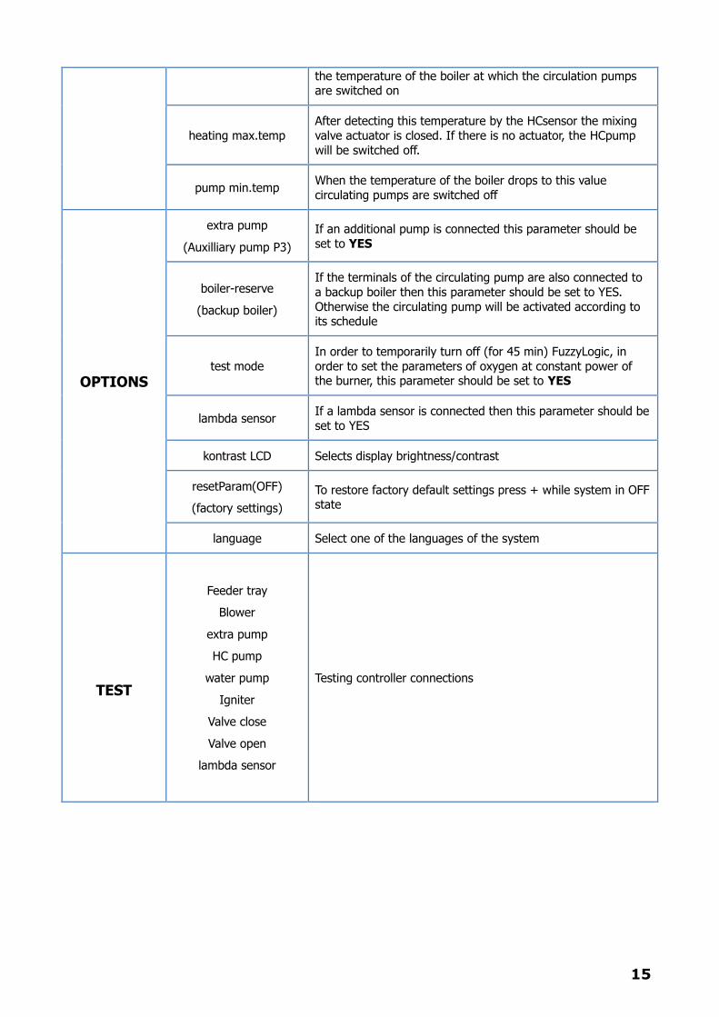
15
the temperature of the boiler at which the circulation pumps are switched on
heating max.temp
After detecting this temperature by the HCsensor the mixing
valve actuator is closed. If there is no actuator, the HCpump
will be switched off.
pump min.temp When the temperature of the boiler drops to this value
circulating pumps are switched off
OPTIONS
extra pump
(Auxilliary pump P3)
If an additional pump is connected this parameter should be
set to YES
boiler-reserve
(backup boiler)
If the terminals of the circulating pump are also connected to
a backup boiler then this parameter should be set to YES.
Otherwise the circulating pump will be activated according to its schedule
test mode
In order to temporarily turn off (for 45 min) FuzzyLogic, in
order to set the parameters of oxygen at constant power of the burner, this parameter should be set to YES
lambda sensor If a lambda sensor is connected then this parameter should be
set to YES
kontrast LCD Selects display brightness/contrast
resetParam(OFF)
(factory settings)
To restore factory default settings press + while system in OFF state
language Select one of the languages of the system
TEST
Feeder tray
Blower
extra pump
HC pump
water pump
Igniter
Valve close
Valve open
lambda sensor
Testing controller connections

16
7. BOILER CONTROL PROGRAMME
7.1. Sensor measurements
All sensors connected to the sensor controller continue to function regardless of system state (ON/OFF).
Even if the boiler stops working or some other malfunction occurs the sensors continue providing data to
the controller. This enables the controller to detect when a defect has been overcome and the system
can be returned to normal operation i.e. when a temperature that is too high or too low is again within
acceptable range.
7.2. LCD display
The LCD display backlight will automatically turn off if no key is pressed for a period of 5 minutes and
the screen will go blank. Pressing any key will turn the backlight back on and return the screen to
normal. The Options sub-menu kontrast LCD is used to set screen brightness on a scale of 0 – 10,
where 0 is blank and 10 is full bright. The recommended brightness level is 4.
7.3. Controller driver pin test
When the system is at idle (OFF on the LCD display) this idle period can be used to test the driver pin of
the controller i.e. to test an output of the controller. To do this enter the sub-menu TEST and select an
output. This starts a countdown of 90 seconds during which period the output is tested. At the end of 90
seconds the countdown function automatically turns off. To test another output repeat the process.
Leaving the test sub-menu returns all tested outputs to their pre-test state. The burner ignition system
can be run in test mode but to protect the igniter element against overheating and possible damage the
test time is limited to 10 seconds.
7.4. Edit/Test mode
This mode is used to adjust the most important parameters of the controller’s function. The password is
used to unblock the access that enables the blower vents and oxygen feed program to be edited. Unless
Test mode has already been turned off manually, entering this area of the program automatically turns
off FuzzyLogic for a period of 45 minutes to allow sufficient time for setting up the parameters
referenced. During this period, the burner operates at the constant output value specified in the sub-
menu BURNER.
WARNING!
Adjusting the blower vent and oxygen feed settings is a skilled task and should only be
performed by a suitably qualified person or an authorized agent. Under no circumstances
should an unqualified person attempt to edit or make changes to this element of the
system.
7.5. Lighting
When the burner is activated after the system is switched from OFF to ON, or when it attempts to relight
from idle following a previous heating cycle, it will automatically start from the ignition stage if suitable
conditions are not detected to maintain a stable flame. It will go through each step sequentially and will
repeat this process up to three times in order to ignite the fuel. If after the third attempt the fuel fails to
17
ignite satisfactorily, the controller displays the caption UNSUCCESSFUL FIRING* and shuts down the
system. If the fuel ignites successfully, the burner goes into normal operation mode and the counter
recording the number of firing attempts is reset to zero. The sequence of steps is shown below and may
vary depending on the mode of operation selected
Stage 1. Initialization
This is the start of a new heating cycle after the boiler has been idle for a short period. An initial
measure of fuel is fed into the burner to start the new cycle and the system then automatically switches
to Stage 2.
Active Element: fuel feeder.
Stage 2. Flame trial
At Stage 2, the system attempts to relight the burner using the residual heat from its previous period of
activity to kindle flame in the initial dose of fuel introduced at Stage 1. To achieve this the blower is
activated to introduce air to assist the combustion process and measured amounts of fuel continue to be
fed into the burner at evenly spaced intervals. If Stage 2 fails to relight the burner the system proceeds
to Stage 3.
Active elements: blower + fuel feeder.
Stage 3. Pre-ignition
Pre-ignition is the process of heating the igniter element to a temperature sufficient to ignite the fuel
accumulated in the burner. When this temperature is reached the system moves on to Stage 4.
Elements switched on: igniter
WARNING!
It is important to pay particular attention to the type and rating of the igniter installed as it
can easily be damaged by overheating. If it is a high power element (over 600W) the
parameter defining the duration of the pre-ignition stage should be set to 0 (zero) which
will bypass stage 3
Stage 4. Ignition
In Stage 4, energy is transferred from the pre-heated igniter element via the blower which forces high
temperature air through the fuel to cause combustion. When flame is produced the blower continues
working in order to spread and strengthen it.
Elements switched on: Igniter + blower.
7.6. Normal mode
Following a successful lighting/re-lighting of the boiler, the system switches to normal operating mode
and stays in this condition until it is either manually turned off or starts to burn-off after completion of
the heating cycle. Normal operating mode is characterized by the way in which the system automatically
calculates fuel delivery (amount of fuel delivered and time intervals of delivery) and blower volume.
Extending the duration of this procedure contributes to raising burner power and this in turn impacts on
18
changes in the operating parameters of these two elements which are calculated automatically. Knowing
the power of the burner enables the system to determine the required value of many other parameters
(e.g. the volume of oxygen needed to ensure efficient combustion) and make them all dynamically
interdependent. Normal operating mode also activates and controls the: DHW circuits, HC circuit with
motorized valve(s), circulation pump and additional pump (where fitted), all of which come on-line after
the boiler has reached operating temperature.
7.7. Anti-block (for pelleted feedstock only)
When operating in MANUAL or WEATHER mode, the boiler shuts down after reaching target
temperature. Every 20 minutes the feeder tray will be turned on and will run for a period of time
specified by the value of the parameter antiblockade. This is to prevent a total loss of the heat in the
burner needed for the next restart.
7.8. Support (ekoCoal feedstock only)
After the boiler reaches target temperature the maintainance of heat/ support stage follows. This stage
is necessary to pre-heat and/or maintain the heat of pea coal in the combustion chamber. After the lapse
of a period of time specified by the value of the parameter support-STOP(maintenance), in the
BURNER sub-menu, the blower is turned on. After 60 seconds the blower will shut down and the feeder
tray will activate for the period of time specified by the value of the parameter support-STRT. Once
this time has elapsed, the feeder tray will shut down and the blower will continue to work for the time
specified by the value of the parameter supp.BlowerAddit. The blower will then stop and after the
waiting time specified by the value of the parameter support-STOP, the process will start again.
7.9. Additional pump
The controller makes provision for an additional pump to be incorporated into the system which can be
used, for example, to provide under-floor heating or divide the heating circuit into two separately
controllable zones via the TZM valve. The additional pump is connected to terminals P3 (pump P3) of the
controller and can be set up to operate in one of two ways, controlled either by time or by temperature.
Method 1. Time control
If the additional pump is required to be run at specified times of the day, this is programmed as follows.
First go to MAIN MENU. Select the CLOCK menu and then select sub-menu P3. In sub-menu P3, use
the EDIT function to enter the times of the day pump P3 is required to run. Return to the CLOCK menu
and select clock options, the first icon in the menu. In this sub-menu set the parameter
additional/extra pump to ON.* Return to MAIN MENU, select OPTIONS and set the parameter extra
pump to YES. The additional pump will now run at the times scheduled.
*NOTE: If this parameter is not set to ON, the system will disregard the time schedule that has been set
and control the additional pump by temperature as Method 2 below.
Method 2. Temperature Control
If pump P3 is required to be available continuously as opposed to being controlled by a time schedule, go
to the CLOCK menu then to the sub-menu clock settings the first icon on the CLOCK menu. Set the
value of the parameter extra pump (additional pump) to OFF, the clock system will now ignore the
settings of the work schedule of P3. Go to MAIN MENU and in the OPTIONS menu set the value of the
parameter extra pump (additional pump) to YES. This confirms to the controller that pump P3 is
connected. Pump P3 will now run on demand according to the temperature of the boiler and/or the hot
19
water circuit (HW). If the priority is set to HW and the water in the calorifier is not heated, pump P3 will
start up only at the intervals determined by the parameters in the HC menu (hating pump-STOP minutes
heating pump-STRT work minutes) until the hot water reaches its target temperature. If hot water
priority is not on or hot water is heated then when the boiler reaches min. temperature P3 is turned on
and switched off only when the temperatures drops to its allowable minimum at the pump.
7.10. Circulation pump
The circulation pump is connected to terminals C/K of the controller. Its function is to provide
hot water to each draw-off point at the desired temperature and in the shortest possible time after a tap
is turned on. The pump is time controlled and can be scheduled to run at specific times of the day and
on specific days of the week. To schedule the pump first go to the MAIN MENU, select the CLOCK
menu and then the sub-menu CIRC. Enter the times of the day and days of the week on which the
pump is to run. When this has been done, go back to the CLOCK menu and select the sub-menu Clock
Settings. Under the sub-heading circulation pump set the value to ON. The pump will now run at the
times scheduled.
NOTE: If a back-up boiler is installed on the system the pump will only run when the primary boiler is in
operation. It will not run when the backup boiler is working.
7.11. Backup Boiler
The controller provides the facility for a backup boiler to be incorporated in the system which can be
placed online if the primary boiler fails to ignite. To setup the backup boiler first go the MAIN MENU and
then select OPTIONS. Select the sub-heading boiler reserve and set the value to YES. With the value
set at YES, should the primary boiler fail to ignite after three firing attempts the caption LIGHTING
FAILED will appear on the controller display. In such circumstance the controller output assigned to the
circulation pump will start but now in relation to the secondary boiler.
WARNING!
If the parameter boiler reserve in the OPTIONS menu, is set to YES, the circulation pump
schedule will not be activated.
7.12. Burning
When the outside air temperature rises, the need for heating inside the property is reduced and thermal
energy accumulated in the tray of the boiler is not required to the same extent as in cold weather. As the
weather warms the heating circuit can be turned off by selecting SUMMER in the boiler menu, which
switches off the HC pump that services the heating circuit. With the boiler now working to provide hot
water only it remains idle for longer periods of time between firings and (where pelleted feedstock is
being used) any residual fuel that remains in the combustion chamber after the hot water target
temperature has been reached is rapidly burned-off to clear the burner ready for the next restart. This
rapid burn-off is achieved by running the blower vent for a set period of time, with the duration of
blower vent activity being determined by the value set under the sub-heading flame extinguish
(burning-off) which can be found in the BURNER sub-menu. The burning-off of residual fuel will also
occur if the controller is switched to OFF.
20
7.13. Time control of the burner
The controller enables the burner to be programmed so that it only runs between the ON/OFF times
scheduled in the clock menu. To setup the schedule first go to the CLOCK menu and then to the sub-
menu BURNER. Use the EDIT function to input the start and finish times required for each cycle.
Return to the CLOCK menu and select the sub-menu for clock Settings which is the first icon on the
CLOCK menu. Select BURNER and set the value to ON*. Using this function to control boiler operation
can yield significant cost savings and it eliminates the need for the user to the turn the boiler on and off
manually.
* If the boiler is required to run continuously as opposed to being time controlled, set this value to OFF.
7.14. Mixing valve
If the system is fitted with a HC temperature sensor coupled to the controller, the presence of a HC loop
mixer valve actuator should be declared in the program by setting the value of the parameter
autom.mixer (Valve Actuator) to YES. This will enable the system to open and close the valve in order to
maintain the desired temperature in the central heating system. If the HC sensor detects a temperature
behind the valve that is too high, the valve will slowly close until the temperature has been reduced to its
desired level and becomes stable. Conversely, if the temperature behind the valve is detected as being
too low, the valve will slowly open until the temperature has increased to the desired level. The value of
using a HC loop mixer valve actuator can not be overstated. By automatically maintaining the
temperature of water in the heating circuit at the correct level it: significantly decreases boiler operating
costs, optimizes the comfort level of the user and eliminates the need to constantly make adjustments to
the heating circuit temperature manually.
8. OPERATOR CONTROL PANEL
Use of the control panel is based on 4 keys (Escape, Plus, Minus, Enter) that are situated vertically to the
right of the LCD display. The function(s) performed by these buttons are as follows:
ESCAPE – The ESCAPE button is multi-functional. When pressing ESCAPE for a minimum of 3
seconds it will change the operating mode of the boiler from OFF to ON or vice versa. Pressing
ESCAPE when in a sub-menu of the program will cause a return to the previous menu. Pressing
ESCAPE after changing the value of a parameter will restore the original value. Pressing ESCAPE
while editing will cancel the current editing process without making changes.
+/- buttons – These two buttons are used to navigate through the main menu and its sub-menus.
They are also used for changing values in sub-menus after previously pressing ENTER.
ENTER – The Enter button is also multi-functional. Press ENTER to access the main menu. Press
ENTER to access a sub-menu (after first using the +/- keys to select the appropriate sub-menu).
Press ENTER to start editing the value of a parameter and press ENTER again to confirm the
changed value. In the TEST menu, press ENTER to include or remove an element.
IMPORTANT!
Depending on the settings selected, the editing of some functions are locked. For example,
when choosing the value YES for the back up boiler in the OPTIONS menu, editing the schedule
for the circulation pump is inaccessible.
21
9. BOILER
9.1. Boiler operating modes
The BOILER sub-menu provides a choice of three modes of boiler operation:
MANUAL - In this mode operating parameters can be set according to preference, which may
be the required temperature of the boiler or CO.
SUMMER - in this mode the heating pump is switched off and only comes online in an
emergency situation (e.g. overheating of the boiler)
WEATHER – the parameters of boiler target temperatures and HC are calculated on the basis of
outside air temperature and the heating curve selected.
9.2. Boiler target temperature
In MANUAL mode and SUMMER mode, boiler target temperature is the desired temperature which has
been set and which the boiler is required to reach and maintain. In WEATHER mode, boiler target
temperature is automatically calculated on the basis of outside air temperature.
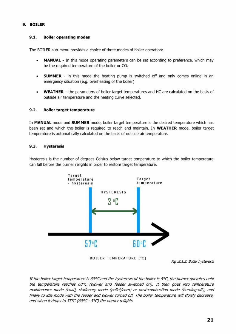
9.3. Hysteresis
Hysteresis is the number of degrees Celsius below target temperature to which the boiler temperature
can fall before the burner relights in order to restore target temperature.
Fig .8.1.3. Boiler hysteresis
If the boiler target temperature is 60°C and the hysteresis of the boiler is 5°C, the burner operates until
the temperature reaches 60°C (blower and feeder switched on). It then goes into temperature
maintenance mode (coal), stationary mode (pellet/corn) or post-combustion mode (burning-off), and
finally to idle mode with the feeder and blower turned off. The boiler temperature will slowly decrease,
and when it drops to 55°C (60°C - 5°C) the burner relights.

22
9.4. System Password
A system password, for use by installation and service engineers, is provided to gain access to certain
parameters that are otherwise blocked against editing.
10. HEATING CIRCUIT - HC
10.1. HC target temperature
HC target temperature is the temperature which the system endeavors to maintain. In WEATHER mode,
target temperature is calculated against outside air temperature and a selected heating curve,
supplemented by input from a room thermostat (where fitted). If a mixing valve actuator is installed, the
actuator will slowly and systematically open or close the valve depending on the actual temperature of
water in the heating circuit relative to HC target temperature.
10.2. Lowering target temperature by room thermostat
The parameter reduction (lowering by room thermostat) in the HC sub-menu, is the value by which the
target temperature should be lowered when the room thermostat signals the controller that the
temperature in the room or area in which it is located has reached the desired level. The room
thermostat can also be programmed to lower the HC target temperature when the property is
unoccupied and/or lower it at night when the occupants of the property are in bed. This avoids the
property being overheated unnecessarily and lowers the cost of running the heating system by reducing
fuel consumption
10.3. Heating curve
The heating curve is a standardized function from which the target temperature of the HC circuit is
calculated based on outside air temperature. The controller enables one of several predefined heat
curves to be selected by the user. If the curve selected does not meet the user’s expectation in terms of
heating effect, the curve can either be corrected (see 8.2.4. below) or an alternative curve can be
selected in its place. The heat curve with the higher ratio (0.4 – 2.2) will, on the basis of outside air
temperature, calculate a higher HC target temperature. As depicted in the graph below, when the
outside air temperature is at 20oC, the lines representing it and HC temperature are close together.
However, as the outside air temperature decreases (moving along the horizontal axis to the right) they
diverge. This illustrates how the system increases HC target temperature as outside air temperature falls
and decreases HC target temperature when outside air temperature rises.
The maximum target temperature calculated on the basis of any particular curve is equal to the value set
in the parameter mixer.max.temp (maximum mixing temperature) minus 5oC. This parameter is
located in the SENSORS menu.

23
Fig.10.3. Heating curves
LEGEND
A Under-floor Heating
B Low-temperature heating system
C High-temperature heating system (T> 75 ° C)
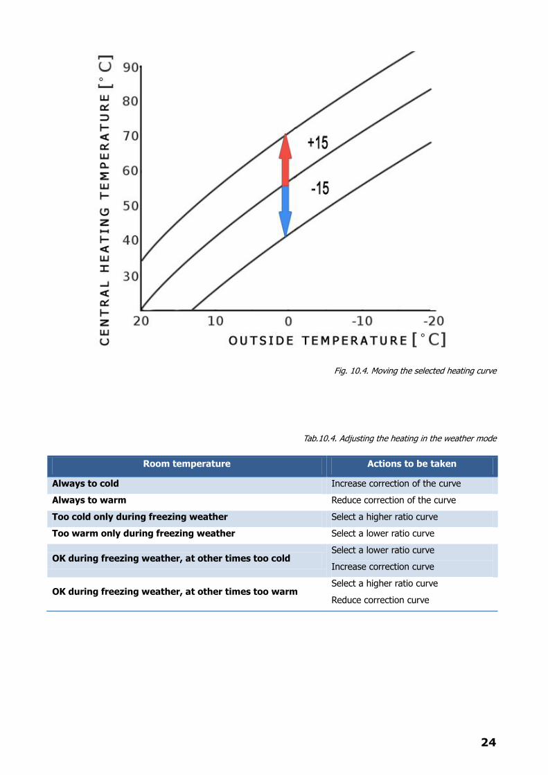
10.4. Curve correction
With the system operating in WEATHER mode, the condition may arise where the HC target temperature
calculated against a selected heating curve does not produce satisfactory results. In such circumstances
the user should correct the curve and/or select and alternative curve. To adjust the curve, go to the HC
menu and select curve correction. Edit the curve value using the +/- keys. Changing the value of this
parameter alters the position of the curve on the graph. Raising the curve increases HC target
temperature, lowering the curve decreases HC target temperature. Fig 8.2.4. below provides a guide to
what action should be taken given a particular type of room temperature condition.
24
Fig. 10.4. Moving the selected heating curve
Tab.10.4. Adjusting the heating in the weather mode
Room temperature Actions to be taken
Always to cold Increase correction of the curve
Always to warm Reduce correction of the curve
Too cold only during freezing weather Select a higher ratio curve
Too warm only during freezing weather Select a lower ratio curve
OK during freezing weather, at other times too cold Select a lower ratio curve
Increase correction curve
OK during freezing weather, at other times too warm Select a higher ratio curve
Reduce correction curve
25
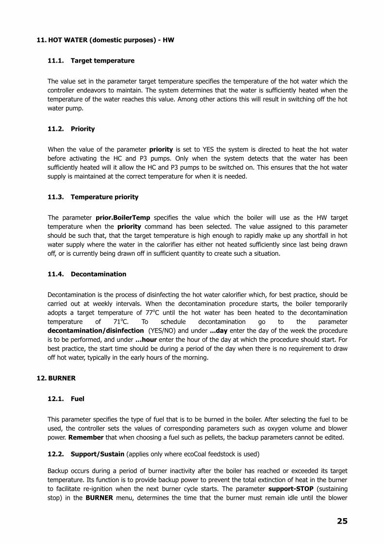
11. HOT WATER (domestic purposes) - HW
11.1. Target temperature
The value set in the parameter target temperature specifies the temperature of the hot water which the
controller endeavors to maintain. The system determines that the water is sufficiently heated when the
temperature of the water reaches this value. Among other actions this will result in switching off the hot
water pump.
11.2. Priority
When the value of the parameter priority is set to YES the system is directed to heat the hot water
before activating the HC and P3 pumps. Only when the system detects that the water has been
sufficiently heated will it allow the HC and P3 pumps to be switched on. This ensures that the hot water
supply is maintained at the correct temperature for when it is needed.
11.3. Temperature priority
The parameter prior.BoilerTemp specifies the value which the boiler will use as the HW target
temperature when the priority command has been selected. The value assigned to this parameter
should be such that, that the target temperature is high enough to rapidly make up any shortfall in hot
water supply where the water in the calorifier has either not heated sufficiently since last being drawn
off, or is currently being drawn off in sufficient quantity to create such a situation.
11.4. Decontamination
Decontamination is the process of disinfecting the hot water calorifier which, for best practice, should be
carried out at weekly intervals. When the decontamination procedure starts, the boiler temporarily
adopts a target temperature of 77oC until the hot water has been heated to the decontamination
temperature of 71oC. To schedule decontamination go to the parameter
decontamination/disinfection (YES/NO) and under ...day enter the day of the week the procedure
is to be performed, and under …hour enter the hour of the day at which the procedure should start. For
best practice, the start time should be during a period of the day when there is no requirement to draw
off hot water, typically in the early hours of the morning.
12. BURNER
12.1. Fuel
This parameter specifies the type of fuel that is to be burned in the boiler. After selecting the fuel to be
used, the controller sets the values of corresponding parameters such as oxygen volume and blower
power. Remember that when choosing a fuel such as pellets, the backup parameters cannot be edited.
12.2. Support/Sustain (applies only where ecoCoal feedstock is used)
Backup occurs during a period of burner inactivity after the boiler has reached or exceeded its target
temperature. Its function is to provide backup power to prevent the total extinction of heat in the burner
to facilitate re-ignition when the next burner cycle starts. The parameter support-STOP (sustaining
stop) in the BURNER menu, determines the time that the burner must remain idle until the blower
26
starts up in backup mode. When the blower is enabled it runs solo for a period of 60 seconds, after
which the feeder tray (activated by the value set in the parameter support-STRT (sustain enter) in the
BURNER menu) provides a measured amount of fuel into the combustion chamber. After the feeder tray
shuts down, the blower resumes working to pre-heat the fuel supplied. The period of time required by
the blower to pre-heat the fuel is represented by the value set in the parameter sup.BlowerAddit(run
blower) in the BURNER menu. The time the burner has to remain idle starts at the beginning of the
cycle described and ends on its completion.
12.3. Anti-block (applies only where pelleted feedstock is used)
When burning pelleted fuel, this parameter specifies the time the feeder tray starts working after the
boiler reaches its target temperature. By default the tray is activated at intervals of 20 minutes. The
purpose of this procedure is to deliver small measures of fuel into the combustion chamber to maintain a
minimum level of heat to facilitate re-ignition when the next burner cycle starts.
12.4. Power test mode
When the user or a service engineer requires to adjust the parameters of boiler operation responsible for
quality of the combustion process, the burner needs to be maintained at a constant power setting while
the adjustments are made and tested. This is not possible to achieve during normal operating mode
because FuzzyLogic continually modulates burner power and tests combustion efficiency accordingly. If
in the OPTIONS menu the parameter test mode is set to YES, for a period of 45 minutes burner
power is maintained at a constant level equal to the value set in the parameter test mode power in the
BURNER menu. It will then be possible to edit the parameters associated with the levels of oxygen
selected for the burner and measure their effectiveness.
12.5. Supply/feeder at 100%
This parameter determines the period of time the feeder tray operates when the boiler is at 100%
power. The time the feeder tray operates at lower power levels is calculated by FuzzyLogic. Since the
optimum efficiency of the combustion process depends wholly on the value of this parameter, such value
should be carefully selected as it will vary according to the type of fuel used (pellets, pea coal, etc.) and
its quality. This parameter can be determine by trial and error, mainly by observing the behavior of the
boiler (whether there is too much or too little fuel, appearance of the flame, etc.) and by noting the
oxygen content in exhaust gas emissions. It is also advisable to read the documentation provided by the
manufacturer of the fuel feed mechanism and in particular to refer to the table of values provided for
this parameter relative to the type of worm gear used.
12.6. Initial supply/feeder
This parameter defines the period of time the feeder tray operates when supplying an initial measure of
fuel at the start of a firing cycle. Note that the amount of fuel supplied should be sufficient to ensure
sustained ignition. Depending on the performance of the feeder mechanism which will vary with type
and manufacture, a sufficiency of fuel should be provided in a feeder runtime of 20 – 60 seconds
12.7. Ignition
This parameter sets the working time of the igniter, without blower activation, to preheat the fuel.
27
WARNING!
Where the power of the igniter element is rated at 600W or above, the value of this
parameter should be set to 0 (zero) in order to avoid possible burnout of the igniter element
and/or its power cables.
12.8. Igniter + blower
This parameter sets the working time of the igniter + blower when firing fuel in the burner. The value
assigned to this parameter should be sufficient to ignite the fuel in the combustion chamber and produce
flame.
12.9. Fire testing
This parameter sets the working time of the burner when the feeder tray and blower are operating in
normal mode. The system checks whether the burner is able to maintain a stable flame. If the system
detects that a stable flame can be sustained, it enters into normal mode bringing the firing sequence to
an end.
12.10. Starting Power
This parameter specifies burner power. At the beginning of a normal mode operating cycle, the burner
power value that has been set provides the basis for setting other operating parameters (feeder, blower
volume, etc.). It also represents the minimum power the burner may have when it slows down before
reaching target boiler temperature.
12.11. Burning
The value set in this parameter determines the duration of the combustion process in burning off
residual fuel remaining in the combustion chamber when the boiler reaches its target temperature. In
other operating modes, the same value determines burner timeout (the period it remains idle between
burning cycles). In both instances the blower is then activated to assist in burning off residual fuel.
Where wood comprises the selected fuel, the boiler operates with the feeder mechanism disconnected
and the system does not monitor the kindling process. Preparation of the boiler to operate with wood
feedstock (depending on its construction) is based on mounting metal shelf angles on the feeder tray
inside the combustion chamber to support an iron grating. Placement of the fuel and its ignition is
achieved manually.
WARNING!
If wood feedstock is used, the exhaust gas sensor must first be removed from the flue.
Leaving it in place could result in it being irreparably damaged.
13. LAMBDA (02)
Measurements from the oxygen sensor are nominally available within 90 seconds after turning the system on
during which period the sensor is in the process of warming up. This is a necessary procedure which
provides a reliable and accurate representation of measurement results. The lambda probe is positioned in
28
the flue and measure combustion parameters by analyzing flue gas emissions. Too low an oxygen level in
the exhaust gas from the boiler results in an increase in blower power to a value calculated by FuzzyLogic.
This is a unique and constantly active corrective function of the system, which dynamically adjusts blower
power in order to maintain an absolute optimum level of oxygen in the combustion process. While being
categorized as an accessory, the lambda probe is nevertheless considered a critical component and its
inclusion in the system is highly recommended as it can increase combustion efficiency by up to 96%.
WARNING!
When cleaning the flue outlet the sensor should be removed from its sleeve. Failure to do this
could result in the sensor being irreparably damaged.
14. BLOWER/FAN
In the sub-menu 02 (FAN/O2) a value can be set to determine the optimum oxygen content in the exhaust
gas at which the boiler achieves the highest level of fuel efficiency. Settings are provided for both Pellet
(pelleted fuel) and ecoCoal (pea coal) which are held in separate libraries in the controller’s memory.
Concurrent with setting optimum oxygen content, blower parameters are also set. This is the strength and
volume of air provided by the blower for the selected burner power. NOTE: Intermediate burner powers not
listed in the menu are calculated by FuzzyLogic.
The parameter inflammation (ignition blower power), which governs the blower when it works in
conjunction with the igniter during the ignition stage (igniter + blower), can be edited as too can the
parameter support power which defines the required strength of the blower in pre-heating pea coal.
In this sub-menu it is also possible to observe the correction value which the system applies to the blower in
order to maintain optimum oxygen content in the exhaust gas at the level selected by the user. Such
correction value becomes available after the lambda probe has warmed up, typically around 1.5 minutes
after initial startup.
15. CLOCK
WARNING!
The power system of the clock will run stable after initially charging its battery - approximately
24-hours. If the program hangs up when it is running, turn off the power supply, wait for a few
seconds and then turn it back on again, this will reset the driver.
In the CLOCK sub-menu the current day and time of day can be edited. There are also parameters for the
circulation pump, additional pump (where fitted) and burner. Setting the value for each of these component
parameters to ON, activates the pumps and burner to a preset schedule.
The steps for editing the schedule for each of these components is identical and the changes introduced are
performed according to an algorithm. First select the appropriate menu (CIRKUL – circulation pump, P3 –
additional pump, or BURNER) and then proceed as follows using the +/- keys to navigate through the sub-
menu headings:
1. Using the +/- keys, enter the day of the week and then press ENTER to confirm the selection.
2. Select the EDIT function and then press ENTER to confirm the selection.
3. Using the +/- keys, enter the program start time and then press ENTER to confirm the selection.
4. Select the run status of the component after the programmed start time (ON it will turned on, OFF
it will be turned off), then press ENTER to confirm the selection.
29
5. Using the +/- keys, enter the end time and then press ENTER to confirm the selection and return to
step 4 (with start time hour equal to that entered in step 5)
6. Press ESCAPE twice to exit or once to return to step 3 (start time hour edit)
While editing the schedule the changes made are displayed on the axis line at the bottom of the operator
panel LCD display. Should it be necessary for the item to remain switched on, say from 1 to 13, all points on
the timeline during this period require to be switched to on. After setting the end time for an activity (e.g.
startup) and selecting ENTER to confirm the selection, proceed to set the time from step 3, where the value
of this parameter will be automatically set to the time of the previous activity, press the ESCAPE key to finish
editing.
Once the work schedule for the selected components is complete it can be copied to other days of the week
where the same work schedule is to apply. To do this, first select the day of the week containing the work
schedule to be copied and then select the COPY option. Using the +/- keys, select the day or days that the
schedule is to be copied to and then press the ENTER key next to each item to be included in the schedule.
After the last item has been entered, complete the procedure by pressing the ENTER key to save the
changes.
16. OPTIONS
16.1. Additional pump
If an additional pump is installed and connected to the controller, say for running an under-floor heating
circuit or separate heating zone, the value of this parameter should be set to YES. Only if this has been
done will pump P3 work according to the time schedule (CLOCK menu, sub-menu P3) or the startup
temperature for switching the pump on (boiler.min.temp/minimum boiler temperature) and the
shutdown temperature for turning it off (pump.min.temp/minimum pump temperature).
16.2. Backup boiler
If the output for switching on the circulation pump is not being used by the driver, the terminals for this
output can be used (if required) for connecting a backup boiler. If the value of the parameter boiler-
reserve is set to YES, the parameter circulation pump in the CLOCK menu is automatically set to
OFF. This output is then switched on at the same time that the message LIGHTING FAILED* appears
on the operator panel LCD display.
16.3. Restoring factory default settings
If changes to the system’s operating parameters adversely affect boiler performance, the controller can
be restored to its factory default settings. To restore the factory default settings, first turn off the boiler
(status OFF). Access reserParam(OFF) (factory settings) in the OPTIONS sub-menu by pressing the
+ Key. Select and then press ENTER to confirm the selection. WARNING: If the boiler is not turned off
prior to restoring the default settings, errors can arise when they are loaded that may subsequently
impair functionality of the controller.
16.4. Lambda sensor
To register connectivity of the lambda probe the value in the parameter sonda lambda (lambda probe)
should be set to YES. If the value is set to NO, the FuzzyLogic element of the lambda probe will be
turned off and the combustion process will not be monitored. This will lead to the deterioration of other

30
parameters dependent on lambda monitoring which in turn will result in a reduction of boiler efficiency
and an increase in fuel consumption.
16.4.1. Język menu (Language menu)
The language menu is used to change the operating language of the controller. To change the language,
access the language and using the +/- keys select the language preferred and then press ENTER to
confirm the selection.
17. TESTING CONTROLLER OUTPUTS
When the controller status is OFF, it is possible to test its individual components (submenu TEST). This is
accomplished by pressing ENTER to change the parameter to ON (enabled). Pressing ENTER again will
return the parameter to OFF (disabled). Pressing ESC while in TEST submenu will set all components to OFF
and exit this submenu.
18. TROUBLESHOOTING
During normal operation of the boiler situations may arise that will serve to either shut the system down,
impair its functionality or modify its mode of operation. Some typical symptoms are described below together
with their probable cause and remedy.
FAILURES LEADING TO SYSTEM SHUTDOWN
Symptom: Overheating of the boiler, where the temperature indicated by the boiler sensor exceeds
the permissible boiler temperature.
Probable cause: Boiler temperature sensor failure, associated with either a missing or damaged
sensor. Will shut down the system completely until the defect is remedied.
Remedy: Inspect the sensor and replace if missing or damaged. If the sensor is not damaged trace
its wiring back to source and check all connections. If the wiring is damaged replace as necessary. If
connections are damaged or insecure replace or make good as required.
Symptom: Overheating of the feeder tray, where the tray temperature exceeds the safe
temperature limit.
Probable cause: Feeder sensor failure, associated with a missing or damaged feeder sensor. Will
shut down the system completely until the defect is remedied.
Remedy: Inspect the sensor and replace if missing or damaged. If the sensor is not damaged trace
its wiring back to source and check all connections. If the wiring is damaged replace as necessary. If
connections are damaged or insecure replace or make good as required.
Symptom: No flue gas temperature recorded or recorded temperature erratic.
Probable cause: Flue gas temperature sensor failure, associated with a missing or damaged
sensor. Will shut down the controller completely until the problem is remedied.
31
Remedy: Inspect the sensor and replace if missing or damaged. If the sensor is not damaged trace
its wiring back to source and check all connections. If the wiring is damaged replace as necessary. If
connections are damaged or insecure replace or make good as required.
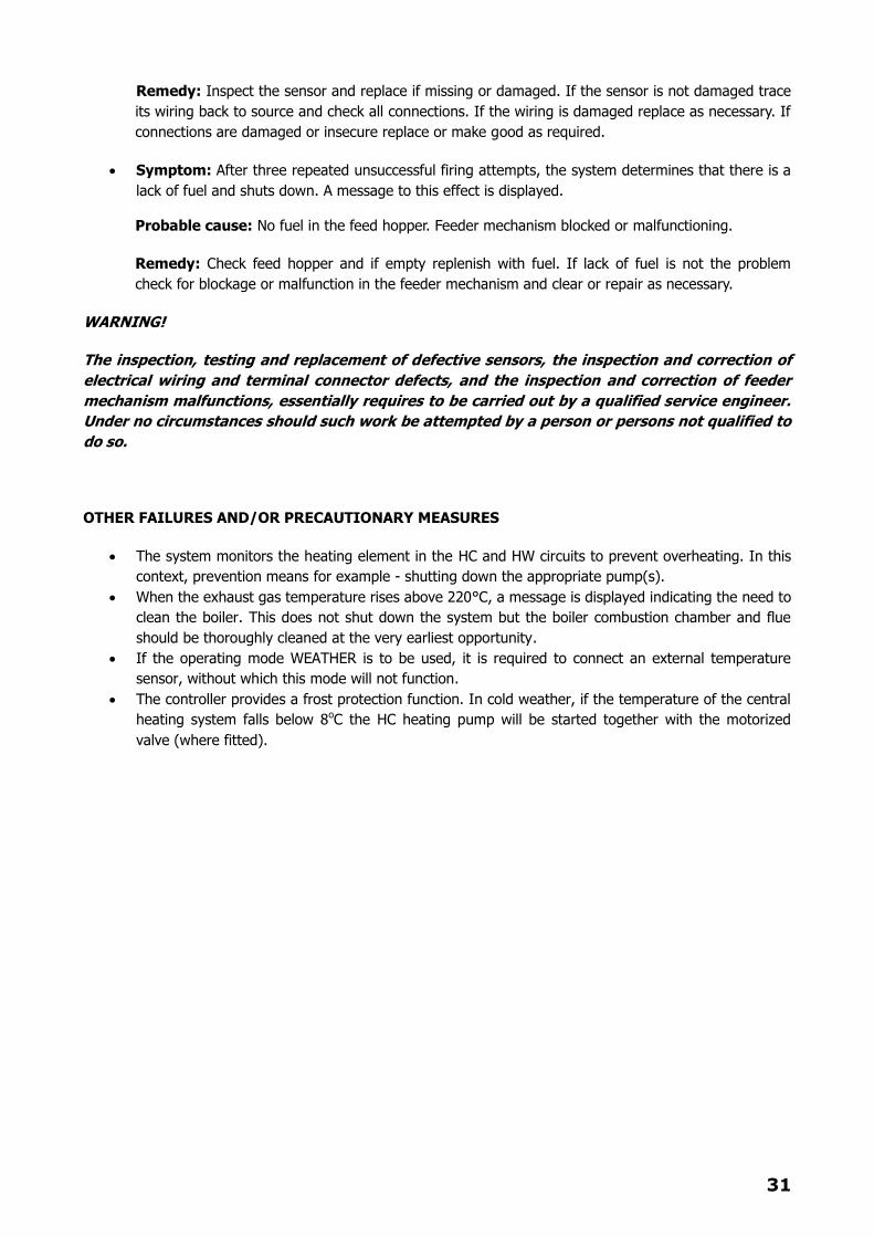
Symptom: After three repeated unsuccessful firing attempts, the system determines that there is a
lack of fuel and shuts down. A message to this effect is displayed.
Probable cause: No fuel in the feed hopper. Feeder mechanism blocked or malfunctioning.
Remedy: Check feed hopper and if empty replenish with fuel. If lack of fuel is not the problem
check for blockage or malfunction in the feeder mechanism and clear or repair as necessary.
WARNING!
The inspection, testing and replacement of defective sensors, the inspection and correction of
electrical wiring and terminal connector defects, and the inspection and correction of feeder
mechanism malfunctions, essentially requires to be carried out by a qualified service engineer.
Under no circumstances should such work be attempted by a person or persons not qualified to
do so.
OTHER FAILURES AND/OR PRECAUTIONARY MEASURES
The system monitors the heating element in the HC and HW circuits to prevent overheating. In this
context, prevention means for example - shutting down the appropriate pump(s).
When the exhaust gas temperature rises above 220°C, a message is displayed indicating the need to
clean the boiler. This does not shut down the system but the boiler combustion chamber and flue
should be thoroughly cleaned at the very earliest opportunity.
If the operating mode WEATHER is to be used, it is required to connect an external temperature
sensor, without which this mode will not function.
The controller provides a frost protection function. In cold weather, if the temperature of the central
heating system falls below 8oC the HC heating pump will be started together with the motorized
valve (where fitted).
32
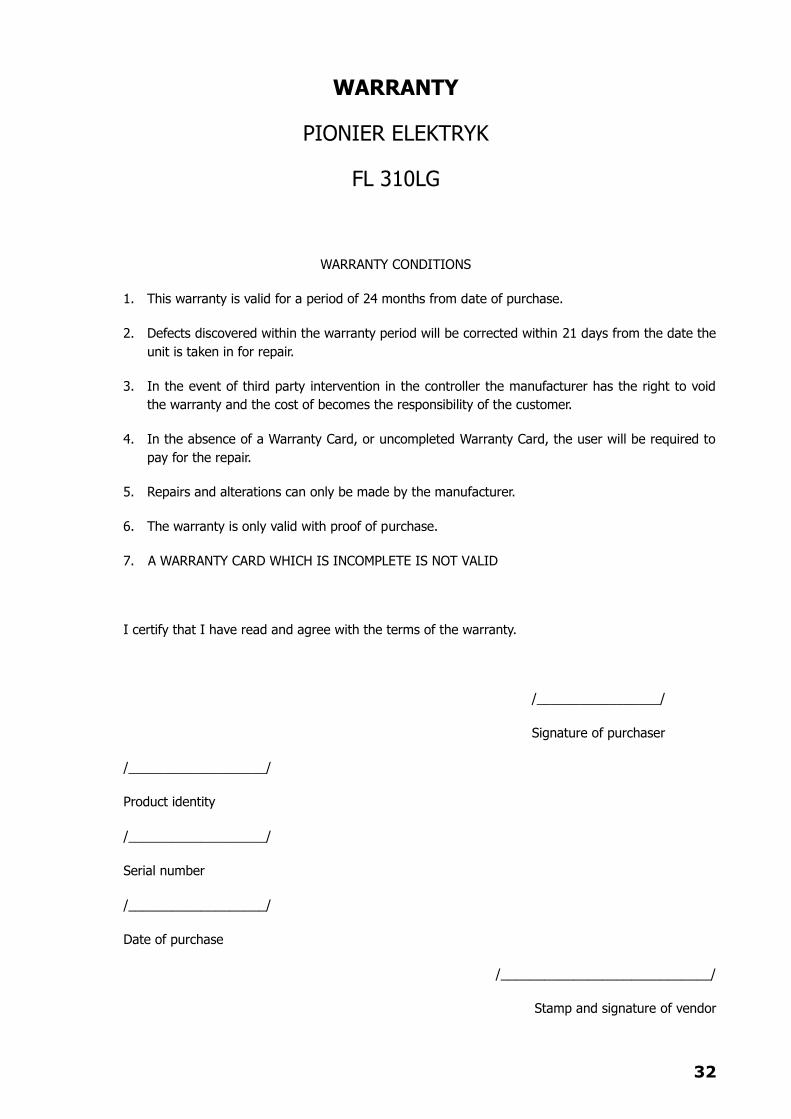
WARRANTY
PIONIER ELEKTRYK
FL 310LG
WARRANTY CONDITIONS
1. This warranty is valid for a period of 24 months from date of purchase.
2. Defects discovered within the warranty period will be corrected within 21 days from the date the
unit is taken in for repair.
3. In the event of third party intervention in the controller the manufacturer has the right to void
the warranty and the cost of becomes the responsibility of the customer.
4. In the absence of a Warranty Card, or uncompleted Warranty Card, the user will be required to
pay for the repair.
5. Repairs and alterations can only be made by the manufacturer.
6. The warranty is only valid with proof of purchase.
7. A WARRANTY CARD WHICH IS INCOMPLETE IS NOT VALID
I certify that I have read and agree with the terms of the warranty.
/_________________/
Signature of purchaser
/___________________/
Product identity
/___________________/
Serial number
/___________________/
Date of purchase
/_____________________________/
Stamp and signature of vendor
33
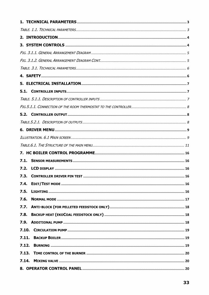
1. TECHNICAL PARAMETERS ........................................................................................................ 3
TABLE. 1.1. TECHNICAL PARAMETERS .................................................................................................................. 3
2. INTRODUCTION .......................................................................................................................... 4
3. SYSTEM CONTROLS ................................................................................................................... 4
FIG. 3.1.1. GENERAL ARRANGEMENT DIAGRAM .................................................................................................. 5
FIG. 3.1.2. GENERAL ARRANGEMENT DIAGRAM CONT. ........................................................................................ 5
TABLE. 3.1. TECHNICAL PARAMETERS .................................................................................................................. 6
4. SAFETY .......................................................................................................................................... 6
5. ELECTRICAL INSTALLATION .................................................................................................... 7
5.1. CONTROLLER INPUTS .................................................................................................................. 7
TABLE. 5.1.1. DESCRIPTION OF CONTROLLER INPUTS ......................................................................................... 7
FIG.5.1.1. CONNECTION OF THE ROOM THERMOSTAT TO THE CONTROLLER ......................................................... 8
5.2. CONTROLLER OUTPUT ................................................................................................................. 8
TABLE.5.2.1. DESCRIPTION OF OUTPUTS ........................................................................................................... 8
6. DRIVER MENU ............................................................................................................................. 9
ILLUSTRATION. 6.1 MAIN SCREEN ....................................................................................................................... 9
TABLE.6.1. THE STRUCTURE OF THE MAIN MENU............................................................................................... 11
7. HC BOILER CONTROL PROGRAMME ..................................................................................... 16
7.1. SENSOR MEASUREMENTS .......................................................................................................... 16
7.2. LCD DISPLAY ........................................................................................................................... 16
7.3. CONTROLLER DRIVER PIN TEST ................................................................................................ 16
7.4. EDIT/TEST MODE ..................................................................................................................... 16
7.5. LIGHTING ................................................................................................................................. 16
7.6. NORMAL MODE ......................................................................................................................... 17
7.7. ANTI-BLOCK (FOR PELLETED FEEDSTOCK ONLY) ....................................................................... 18
7.8. BACKUP HEAT (EKOCOAL FEEDSTOCK ONLY) ............................................................................ 18
7.9. ADDITIONAL PUMP ................................................................................................................... 18
7.10. CIRCULATION PUMP ............................................................................................................... 19
7.11. BACKUP BOILER ..................................................................................................................... 19
7.12. BURNING ............................................................................................................................... 19
7.13. TIME CONTROL OF THE BURNER ............................................................................................. 20
7.14. MIXING VALVE ....................................................................................................................... 20
8. OPERATOR CONTROL PANEL ................................................................................................. 20

34
9. BOILER ........................................................................................................................................ 21
9.1. BOILER OPERATING MODES ...................................................................................................... 21
9.2. BOILER TARGET TEMPERATURE ................................................................................................. 21
9.3. HYSTERESIS ............................................................................................................................. 21
FIG .8.1.3. BOILER HYSTERESIS ...................................................................................................................... 21
9.4. SYSTEM PASSWORD ................................................................................................................. 22
10. HEATING CIRCUIT ................................................................................................................... 22
10.1. HC TARGET TEMPERATURE ..................................................................................................... 22
10.2. LOWERING TARGET TEMPERATURE BY ROOM THERMOSTAT .................................................... 22
10.3. HEATING CURVE ..................................................................................................................... 22
FIG.10.3. HEATING CURVES ............................................................................................................................. 23
10.4. CURVE CORRECTION ............................................................................................................... 23
FIG. 10.4. MOVING THE SELECTED HEATING CURVE .......................................................................................... 24
TAB.10.4. ADJUSTING THE HEATING IN THE WEATHER MODE ............................................................................. 24
11. HOT WATER (DOMESTIC PURPOSES) .................................................................................. 25
11.1. TARGET TEMPERATURE ........................................................................................................... 25
11.2. PRIORITY ............................................................................................................................... 25
11.3. TEMPERATURE PRIORITY........................................................................................................ 25
11.4. DECONTAMINATION ............................................................................................................... 25
12. BURNER ...................................................................................................................................... 25
12.1. FUEL ....................................................................................................................................... 25
12.2. SUPPORT/SUSTAIN (APPLIES ONLY WHERE ECOCOAL FEEDSTOCK IS USED).......................... 25
12.3. ANTI-BLOCK (APPLIES ONLY WHERE PELLETED FEEDSTOCK IS USED) .................................... 26
12.4. POWER TEST MODE ................................................................................................................. 26
12.5. SUPPLY/FEEDER AT 100% .................................................................................................... 26
12.6. INITIAL SUPPLY/FEEDER ........................................................................................................ 26
12.7. IGNITION ............................................................................................................................... 26
12.8. IGNITER + BLOWER ............................................................................................................... 27
12.9. FIRE TESTING ......................................................................................................................... 27
12.10. STARTING POWER ............................................................................................................... 27
12.11. BURNING ............................................................................................................................. 27
13. LAMBDA (02) ............................................................................................................................. 27
14. BLOWER/FAN ............................................................................................................................ 28
35
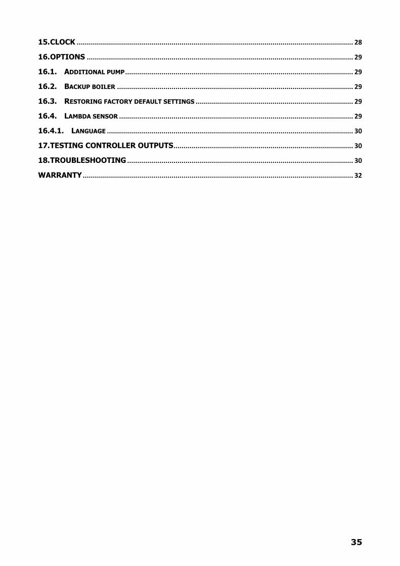
15. CLOCK ......................................................................................................................................... 28
16. OPTIONS .................................................................................................................................... 29
16.1. ADDITIONAL PUMP ................................................................................................................. 29
16.2. BACKUP BOILER ..................................................................................................................... 29
16.3. RESTORING FACTORY DEFAULT SETTINGS .............................................................................. 29
16.4. LAMBDA SENSOR .................................................................................................................... 29
16.4.1. LANGUAGE .......................................................................................................................... 30
17. TESTING CONTROLLER OUTPUTS ......................................................................................... 30
18. TROUBLESHOOTING ................................................................................................................ 30
WARRANTY ...................................................................................................................................... 32


![RTC Pharma07CatalogWeb[1]](https://img.pdfslide.us/doc/110x75/55cf8de4550346703b8c6188/rtc-pharma07catalogweb1.jpg)