Embed Size (px)
Citation preview

What is the Role of MIMO in Future Cellular Networks:
Massive? Coordinated? mmWave?Robert W. Heath Jr.
The University of Texas at Austin Wireless Networking and Communications Group
www.profheath.orgPresentation (c) Robert W. Heath Jr. 2013

(c) Robert W. Heath Jr. 2013
Wireless is Big in Texas
150 Grad Students
Affiliates champion large federal proposals, provide technical
input/feedback, unrestricted gi: funds
WNCG provides pre-‐prints, pre-‐compe@@ve research ideas, vast exper@se, first access to students
About half of all students intern for an affiliate or work full-‐@me
Affiliates provide real world context
12 Industrial Affiliates20 Faculty

Wireless Communications LabUndergrad/grad lab course
QAM & OFDM experiments
Complete lab manual & software
Uses USRP equipment
LabVIEW programming
Complete lab manual available
�3
Dr. Robert W. Heath, University of Texas at Austin
DIGITAL COMMUNICATIONS
PHYSICAL LAYER EXPLORATION LAB USING THE NI USRP™ PLATFORM
front.pdf 1 9/12/11 4:46 PM
http://sine.ni.com/nips/cds/view/p/lang/en/nid/210087

OutlineMIMO in cellular networks
Coordinated Multipoint a.k.a. network MIMO
Massive MIMO
Millimeter wave MIMO
Comparison between technologies
Parting thoughts
�4
(c) Robert W. Heath Jr. 2013
The MIMO Concept
MIMO (multiple-input multiple-output) communication channel Leverages multiple antennas at the transmitter and receiver
MIMO is broadly incorporated into wireless systems Cellular communication, wireless local area networks, ad hoc networks
Provides capacity, quality, robustness, resilience to interference
�5
MIMO communication exploits matrix propagation channels
Transmitter Receiver
multiple inputs
multiple outputs
Hpropagation
channelmultiple
TX antennasmultiple
RX antennas

(c) Robert W. Heath Jr. 2013
Point-to-Point MIMO
Single user MIMO communication Send multiple data streams a.k.a. spatial multiplexing
Highest performance requires rich scattering environment
Incorporated into several commercial wireless systems
Ex: 8 antennas at the base station and 4 antennas at the mobile station
�6
Multiplexing gains are limited by number of antennas at users
# of parallel data streams is the multiplexing gain
2 data streams

(c) Robert W. Heath Jr. 2013
Point-to-Multipoint MIMO
Multiuser MIMO (MU-MIMO) Simultaneously send independent data streams to several users
Multiplexing gains are obtained even with less ideal propagation
Main obstacles: near-far problem & channel correlation
Flexibility in user scheduling may overcome the obstacles
�7
Multiplexing gains are limited by number of antennas at base stations
2 data streams
2 data streams
4 streams total
(c) Robert W. Heath Jr. 2013
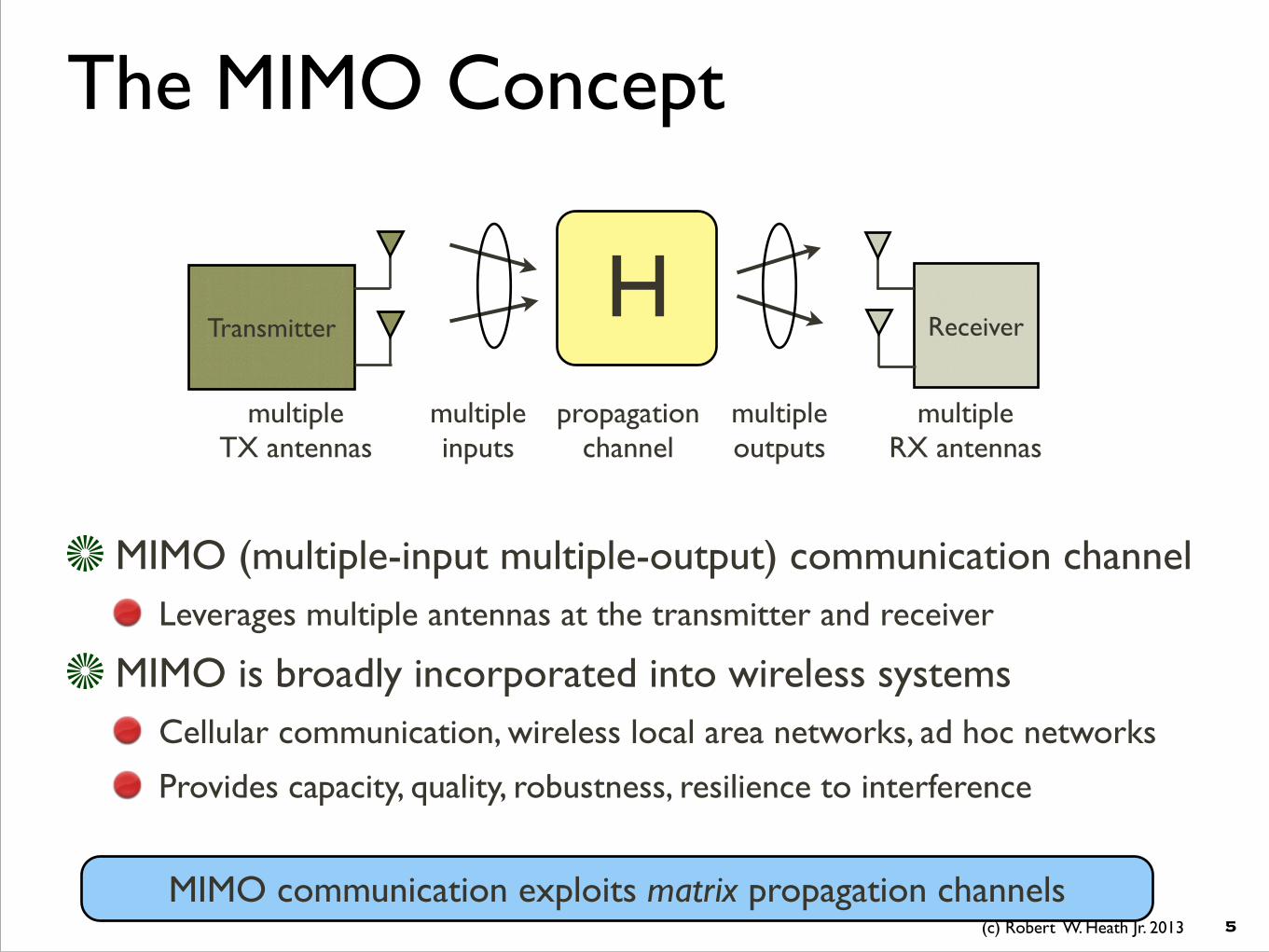
Where is MIMO Headed?
�8
Massive MIMOB
mmWave MIMO
Coordinated MIMO
Candidate architectures for 5G

OutlineMIMO in cellular networks
Coordinated Multipoint a.k.a. network MIMO
Massive MIMO
Millimeter wave MIMO
Comparison between technologies
Parting thoughts
�9
(c) Robert W. Heath Jr. 2013
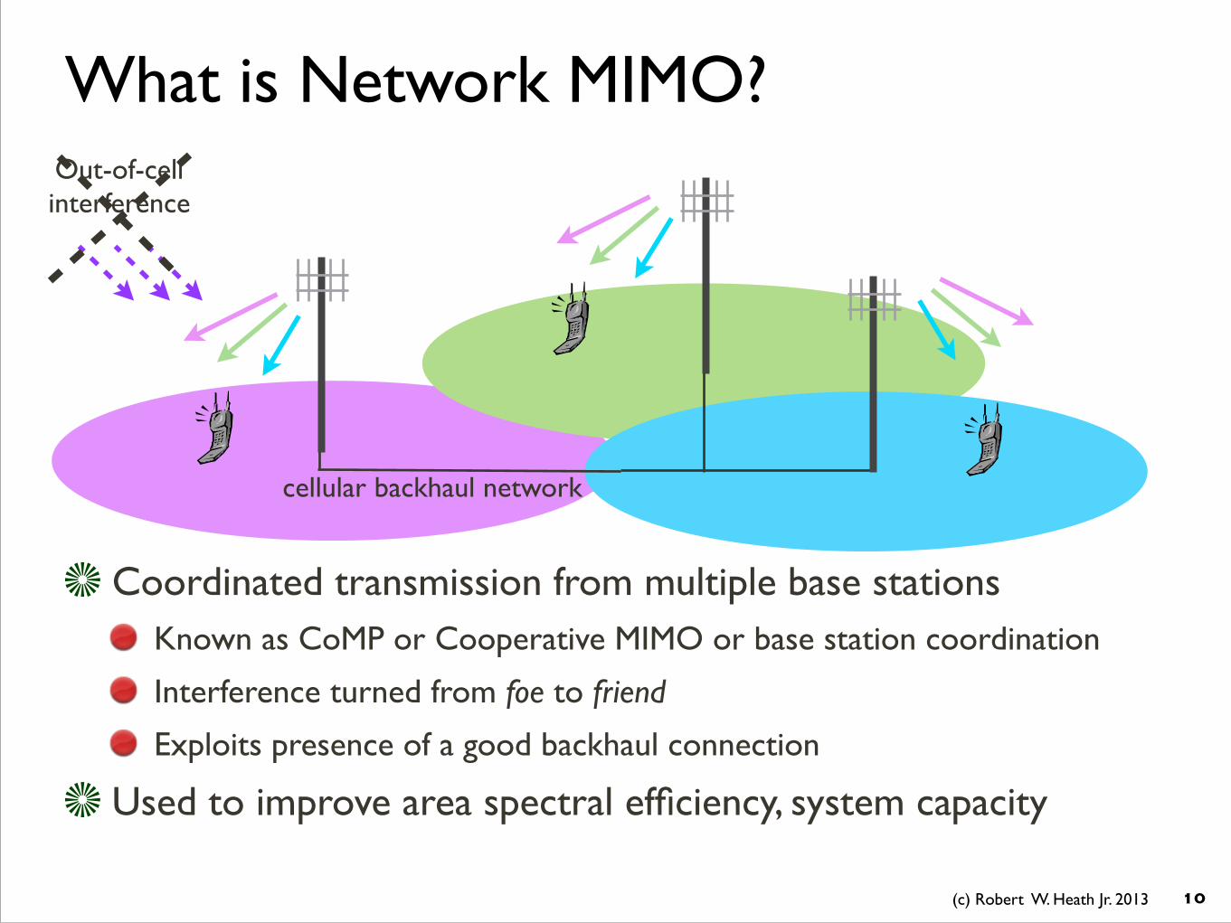
What is Network MIMO?
Coordinated transmission from multiple base stations Known as CoMP or Cooperative MIMO or base station coordination
Interference turned from foe to friend
Exploits presence of a good backhaul connection
Used to improve area spectral efficiency, system capacity
�10
Out-of-cell interference
cellular backhaul network
(c) Robert W. Heath Jr. 2013
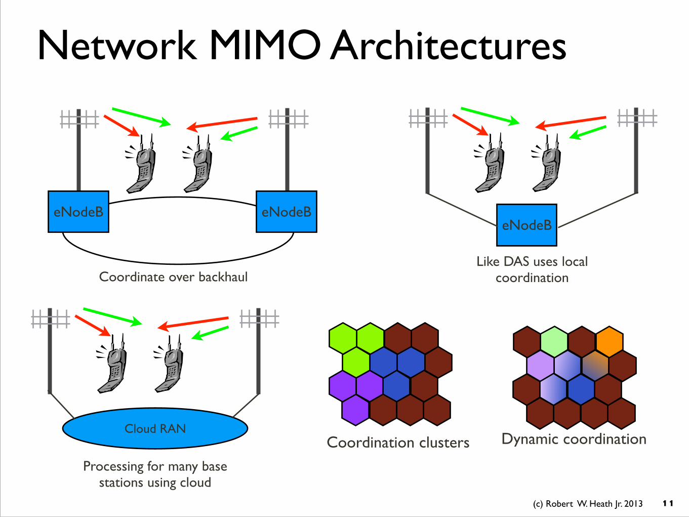
Network MIMO Architectures
�11
Coordinate over backhaul
eNodeB eNodeBeNodeB
Like DAS uses local coordination
Cloud RAN
Processing for many base stations using cloud
Coordination clusters Dynamic coordination

(c) Robert W. Heath Jr. 2013
Throughput gains when out-of-cluster interference is ignored More cooperation leads to higher gains
Cell edge pushed further out, no uncoordinated interference in the cell
Potential Gains from Coordination
�12
0 5 10 15 20 25 300
10
20
30
40
50
60
70
80
90
SNR (dB)Su
m-ra
tes
(bits
/sec
/Hz)
K=1 K=3K=9
−1500 −1000 −500 0 500 1000 1500−1500
−1000
−500
0
500
1000
1500
Linear increase
BSMSISD=500m
19 cells and 3 sectors per cellBS-MS distance= 192 m
Grid model for a cellular network
Unbounded gains
sum rates per cell

(c) Robert W. Heath Jr. 2013
Performance saturates with out-of-cluster interference
30% performance gains observed in industrial settings
Addressing Out-of-Cell Interference
�13
0 5 10 15 20 25 300
5
10
15
20
25
SNR (dB)
Sum
-rate
s (b
its/s
ec/H
z)
K=1K=3K=9
Sum-rates saturation
−1500 −1000 −500 0 500 1000 1500−1500
−1000
−500
0
500
1000
1500
BSMSISD=500m
19 cells and 3 sectors per cellBS-MS distance= 192 m
Grid model for a cellular network
Bounded gains
Be mindful of the saturation point
A. Lozano, R. W. Heath, Jr., and J. G. Andrews, ``Fundamental Limits of Cooperation" to appear in the IEEE Trans. on Info. Theory. Available on ArXiv.

(c) Robert W. Heath Jr. 2013
Critical Issues with Network MIMOOut-of-cell interference
When included, results are not as good
Feedback overhead Need channel state information
Performance seriously degrades
Control channel overhead Increased reference signal overhead
Backhaul link constraints Backhaul link latency (delayed CSI and data sharing)
Cluster edge effects Coordination still has a cell edge with fixed clusters
Dynamic clustering solves the problem, but more more implementation overhead
�14
Backhaul delay
eNodeB eNodeB
channel state feedback overhead
Data payloadReference signal

(c) Robert W. Heath Jr. 2013
Network MIMO Conclusions
�15
Observations Network MIMO promises a way to get rid of interference
...Yet uncoordinated interference still limits high SNR performance
Backhaul constraints and system overheads further reduce performance gains
General disconnect between academia and industry on the potential
Forecast Already incorporated into 4G, coordination will be part of 5G as well
Architectures will evolve to support network MIMO-like coordination
• Distributed antenna systems are a good starting point
• Distributed radio access networks are a likely evolution point
• Cloud radio access networks are a possible end objective

OutlineMIMO in cellular networks
Coordinated Multipoint a.k.a. network MIMO
Massive MIMO
Millimeter wave MIMO
Comparison between technologies
Parting thoughts
�16

(c) Robert W. Heath Jr. 2013
What is Massive MIMO?
A very large antenna array at each base station An order of magnitude more antenna elements in conventional systems
A large number of users are served simultaneously
An excess of base station (BS) antennas
�17
Essentially multiuser MIMO with lots of base station antennas
hundreds of BS antennas
tens of users
T. L. Marzetta, “Noncooperative cellular wireless with unlimited numbers of base station antennas,” IEEE Trans. Wireless Commun., vol. 9, no. 11, pp. 3590–3600, Nov. 2010.

(c) Robert W. Heath Jr. 2013
Massive MIMO Key Features
Benefits from the (many) excess antennas
Simplified multiuser processing
Reduced transmit power
Thermal noise and fast fading vanish
Differences with MU MIMO in conventional cellular systems
Time division duplexing used to enable channel estimation
Pilot contamination limits performance�18
F. Rusek, D. Persson, B. K. Lau, E. G. Larsson, T. L. Marzetta, O. Edfors, and F. Tufvesson, “Scaling up MIMO: Opportunities and challenges with very large arrays,” IEEE Signal Processing Mag., vol. 30, no. 1, pp. 40–60, Jan. 2013.
pilot contamination
Uplink trainingDownlink channel
reciprocity
asymptotic orthogonality
interference

(c) Robert W. Heath Jr. 2013
Centralized vs. Distributed
Fixed number of base station antennas per cell
�19
BS
�� �� � ��� �����
��
�
���
���BS antenna
clusters
�� �� � ��� �����
��
�
���
���
7 cells without sectorization 12 users uniformly distributed in each cell
ISD = 500mCentralized Distributed
* K. T. Truong and R. W. Heath, Jr., “Impact of Spatial Correlation and Distributed Antennas for Massive MIMO systems,” to appear in the Proceedings of the Asilomar Conference on Signals, Systems, and Computers, Nov. 3-6, 2013.
(c) Robert W. Heath Jr. 2013
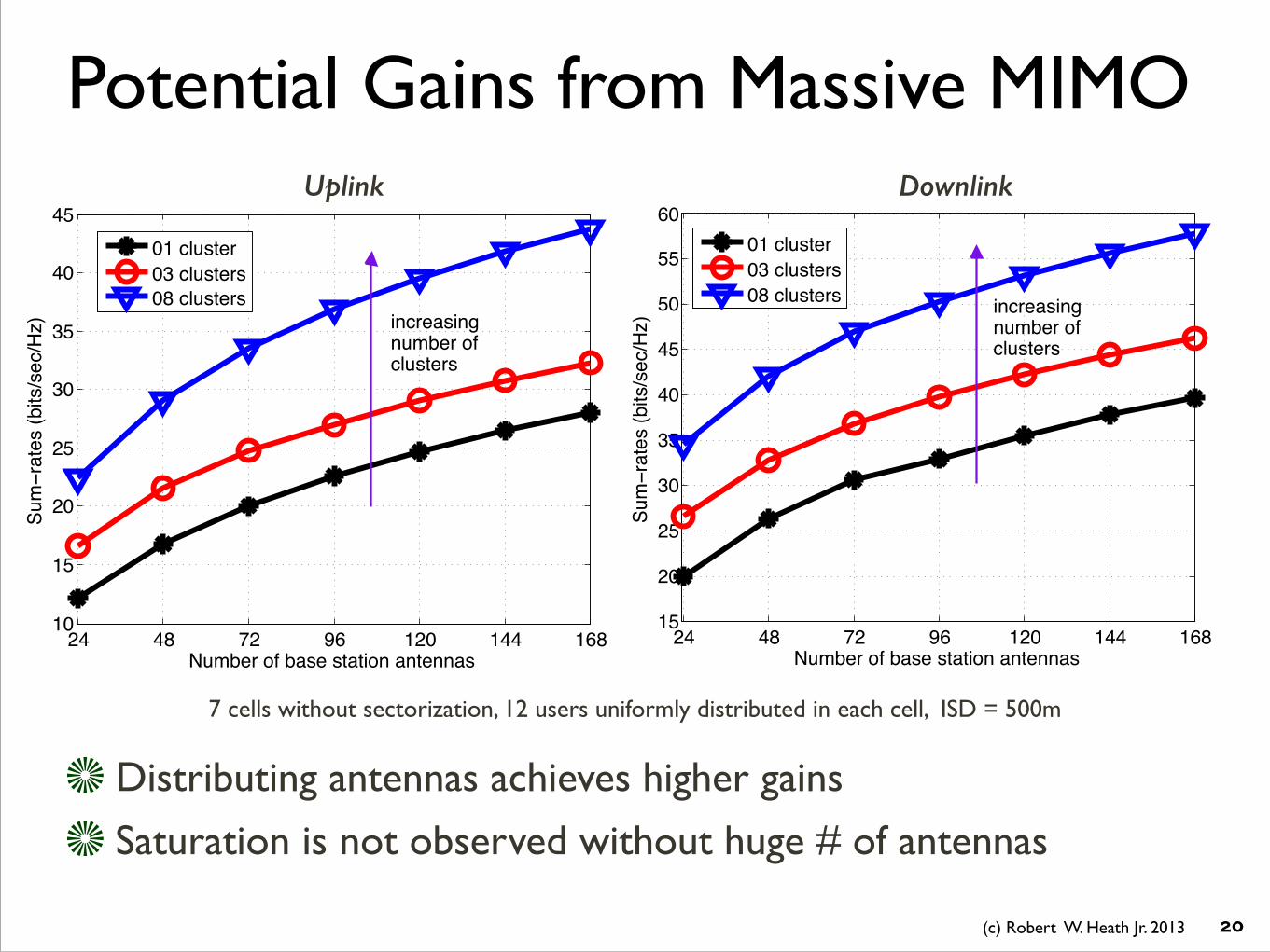
Potential Gains from Massive MIMO
Distributing antennas achieves higher gains
Saturation is not observed without huge # of antennas
�20
24 48 72 96 120 144 16815
20
25
30
35
40
45
50
55
60
Number of base station antennas6X
PïUDWHV��ELWV�VHF�+]�
���FOXVWHU���FOXVWHUV���FOXVWHUV LQFUHDVLQJ
number ofFOXVWHUV
24 48 72 96 120 144 16810
15
20
25
30
35
40
45
Number of base station antennas
6XPïUDWHV��ELWV�VHF�+]�
���FOXVWHU���FOXVWHUV���FOXVWHUV
LQFUHDVLQJnumber ofFOXVWHUV
DownlinkUplink
7 cells without sectorization, 12 users uniformly distributed in each cell, ISD = 500m

(c) Robert W. Heath Jr. 2013
Critical Issues in Massive MIMOGains are not that big with not-so-many antennas
Require many antennas to remove interference
Need more coordination to remove effects of pilot contamination
Massive MIMO seems to be more “uplink driven” Certain important roles are reserved between base stations and users
A different layout of control and data channels may be required
Practical effects are not well investigated Channel aging affects energy-focusing ability of narrow beams
Spatial correlation reduces effective DoFs as increasing number of antennas
Role of asynchronism in pilot contamination and resulting performance
�21

(c) Robert W. Heath Jr. 2013
Massive MIMO ConclusionsObservations
Pilot contamination is a big deal, but possibly overcome by coordination
Performance is sensitive to channel aging effects *
Good performance can be achieved with distributed antennas *
Not clear how to pack so many microwave antennas on a base station
Needs more extensive simulation study with realistic system parameters
Forecast Massive MIMO will probably not be used in isolation
Will be combined with distributed antennas or base station coordination
• Reduces the effects of pilot contamination
• Work with smaller numbers of antennas
�22* K. T. Truong and R. W. Heath, Jr., “Effects of Channel Aging in Massive MIMO Systems,” to appear in the Journal of Communications and Networks, Special Issue on Massive MIMO, February 2013.

OutlineMIMO in cellular networks
Coordinated Multipoint a.k.a. network MIMO
Massive MIMO
Millimeter wave MIMO
Comparison between technologies
Parting thoughts
�23
(c) Robert W. Heath Jr. 2013
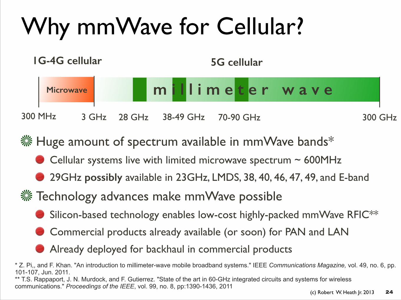
Why mmWave for Cellular?
Microwave
3 GHz 300 GHz
�24
28 GHz 38-49 GHz 70-90 GHz300 MHz
Huge amount of spectrum available in mmWave bands* Cellular systems live with limited microwave spectrum ~ 600MHz
29GHz possibly available in 23GHz, LMDS, 38, 40, 46, 47, 49, and E-band
Technology advances make mmWave possible Silicon-based technology enables low-cost highly-packed mmWave RFIC**
Commercial products already available (or soon) for PAN and LAN
Already deployed for backhaul in commercial products
1G-4G cellular 5G cellular
m i l l i m e t e r w a v e
* Z. Pi,, and F. Khan. "An introduction to millimeter-wave mobile broadband systems." IEEE Communications Magazine, vol. 49, no. 6, pp.101-107, Jun. 2011. ** T.S. Rappaport, J. N. Murdock, and F. Gutierrez. "State of the art in 60-GHz integrated circuits and systems for wireless communications." Proceedings of the IEEE, vol. 99, no. 8, pp:1390-1436, 2011

(c) Robert W. Heath Jr. 2013
Smaller wavelength means smaller captured energy at antenna 3GHz->30GHz gives 20dB extra path loss due to aperture
Larger bandwidth means higher noise power and lower SNR 50MHz -> 500MHz bandwidth gives 10dB extra noise power
The Need for Gain
�25
Solution: Exploit array gain from large antenna arrays
microwave noise bandwidth
mmWave noise bandwidth
microwave aperture
mmWave aperture
TXRX
�2
4⇡

(c) Robert W. Heath Jr. 2013
Antenna Arrays are Important
�26
Narrow beams are a new feature of mmWave Reduces fading, multi-path, and interference
Implemented in analog due to hardware constraints
Baseband Processing
~100 antennas
Baseband Processing
antennas are small (mm)
highly directional MIMO transmission
used at TX and RX
Arrays will change system design principles

(c) Robert W. Heath Jr. 2013
Coverage Gains from Large Arrays
�27
Serving BS
Typical User
PPP Interfering BSs
Buildings
LOS & blocked path loss model from measurements. A Poisson layout of mmWave BSs. Average cell radius Rc=100m. A Boolean scheme building model.
mmWave networks can provide acceptable coverage Directional array gain compensates severe path loss
Smaller beamwidth reduces the effect of interference
1
Summary of Cellular Millimeter Wave Channels
I. MEASUREMENT RESULTS
−10 −8 −6 −4 −2 0 2 4 6 8 100.2
0.3
0.4
0.5
0.6
0.7
0.8
0.9
1
SINR Threshold in dB
Cov
erag
e Pr
obab
ility
Omni DirectionalDirectional: HPBW=40o
Directional: HPBW=10o
Fig. 1.
−10 −8 −6 −4 −2 0 2 4 6 8 100
0.1
0.2
0.3
0.4
0.5
0.6
0.7
0.8
0.9
1
SINR threshold in dB
Cov
erag
e Pr
obab
ility
Omni−DirectionalNt=3, HPBW=0.2π
Nt=4, HPBW=0.15π
Nt=5, HPBW=0.12π
Nt=10, HPBW=0.06π
MicrowaveOut of Range: Nt=10
Fig. 2.
Gain from directional antenna array

(c) Robert W. Heath Jr. 2013
Critical Issues in mmWave MIMO
Dealing with hardware constraints Need a combination of analog and digital beamforming
Array geometry may be unknown, may change
Performance in complex propagation environments Evaluate performance with line-of-sight and blocked signal paths
Must adapt to frequent blockages and support mobility
Entire system must support directionality
Need approval to employ the spectrum
�28

(c) Robert W. Heath Jr. 2013
mmWave ConclusionsObservations
Coverage may be acceptable with the right system configuration
Strong candidate for higher per-link data rates
Hardware can leverage insights from 60GHz LAN and PAN
Highly directional antennas may radically change system design
Supporting mobility may be a challenge
Forecast Will be part of 5G if access to new spectrum becomes viable
Most likely will co-exist with microwave cellular systems
Will remain useful for niche applications like backhaul
�29

OutlineMIMO in cellular networks
Coordinated Multipoint a.k.a. network MIMO
Massive MIMO
Millimeter wave MIMO
Comparison between technologies
Parting thoughts
�30

(c) Robert W. Heath Jr. 2013
Stochastic Geometry for Cellular
Stochastic geometry is a tool for analyzing microwave cellular Reasonable fit with real deployments
Closed form solutions for coverage probability available
Provides a system-wide performance characterization
�31
J. G. Andrews, F. Baccelli, and R. K. Ganti, "A Tractable Approach to Coverage and Rate in Cellular Networks", IEEE Transactions on Communications, November 2011.!T. X. Brown, "Cellular performance bounds via shotgun cellular systems," IEEE JSAC, vol.18, no.11, pp.2443,2455, Nov. 2000.
base station locations distributed (usually) as a
Poisson point process (PPP)performance analyzed for a typical user
Need to incorporate features of each technology
Baccelli

(c) Robert W. Heath Jr. 2013
Comparing Different Approaches
�32
CoMP model Sectored cooperation model
Typical user can be edge or center user of the cluster
Several assumptions made to permit calculation
mmWave model Directional antennas are incorporated as marks of the base station PPP
Blockages due to buildings incorporated via random shape theory
Massive MIMO model Analyze asymptotic case with infinite number of antennas at the base station
No spatial correlation, includes estimation error, pilot contamination
New expressions derived for each case
Tianyang Bai and R. W. Heath, Jr., `` Asymptotic Coverage Probability and Rate in Massive MIMO Networks ,'' submitted to IEEE Wireless Communications Letters, May 2013. Available on ArXiv.!Tianyag Bai and R. W. Heath Jr., ``Performance Analysis of mmWave Cellular Systems,’’ under preparation.
15
Fig. 8. .

(c) Robert W. Heath Jr. 2013
SINR Coverage Comparison
�33
5
−10 −5 0 5 10 15 200.1
0.2
0.3
0.4
0.5
0.6
0.7
0.8
0.9
1
SINR Threhold in dB
SIN
R C
ov
era
ge
Pro
ba
bil
ity
CoMP: Nt=4, 2 Users, 3 BSs/ Cluster
Massive MIMO: Nt=∞
mmWave: Nt=64, R
c=100m
SU MIMO: 4X4
Fig. 1.
Gain from directional antennas and blockages
in mmWave
Gain from larger number of antennas
SINR CCDF

(c) Robert W. Heath Jr. 2013
6
0 5 10 150
0.1
0.2
0.3
0.4
0.5
0.6
0.7
0.8
0.9
1
Spectrum Efficiency (bps/Hz)
Ra
te C
ov
era
ge
Pro
ba
bil
ity
CoMP: Nt=4, 2 Users, 3 BSs/ Cluster
Massive MIMO: Nt=∞
mmWave: Nt=64, R
c=100m
SU MIMO: 4X4
Fig. 2.
Coverage Comparison
�34
Gain from directional antennas and blockages in mmWave
Gain from massive number of antennas
Spectrum Efficiency CCDF
(c) Robert W. Heath Jr. 2013
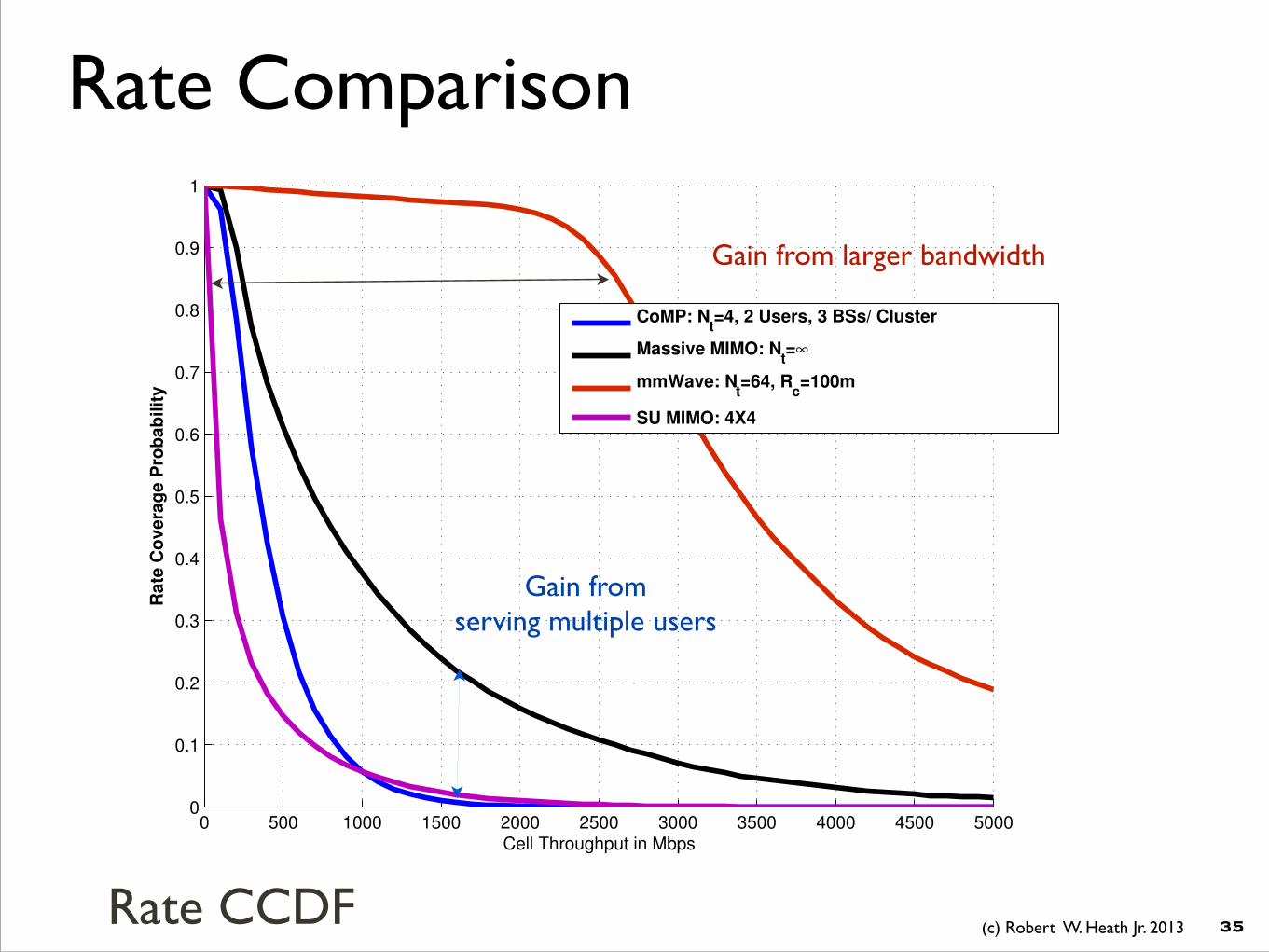
Rate Comparison
�35
7
0 500 1000 1500 2000 2500 3000 3500 4000 4500 50000
0.1
0.2
0.3
0.4
0.5
0.6
0.7
0.8
0.9
1
Cell Throughput in Mbps
Ra
te C
ov
era
ge
Pro
ba
bil
ity
CoMP: Nt=4, 2 Users, 3 BSs/ Cluster
Massive MIMO: Nt=∞
mmWave: Nt=64, R
c=100m
SU MIMO: 4X4
Fig. 3.
Gain from larger bandwidth
Gain from serving multiple users
Rate CCDF

(c) Robert W. Heath Jr. 2013
Rate Comparison
�36
Massive MIMO
MMwave CoMP SU MIMO
Signal BW 50 MHz 500 MHz 50 MHz 50 MHz
User/ Cell 8 1 2 1
bps/Hz per user 5.47 bps/Hz 8.00 bps/Hz 4.34 bps/Hz 4.95 bps/Hz
Rate/Cell 21.88 bps/Hz 8.00 bps/Hz 8.68 bps/Hz 4.95 bps/Hz
Capacity/ Cell 1.10 Gbps 4.00 Gbps 434 Mbps 248 Mbps
mmWave outperforms due to more available BW
* of course various parameters can be further optimized ** SU MIMO is 4x4 w/ zero-forcing receiver

OutlineMIMO in cellular networks
Coordinated Multipoint a.k.a. network MIMO
Massive MIMO
Millimeter wave MIMO
Comparison between technologies
Parting thoughts
�37

(c) Robert W. Heath Jr. 2013
Parting Thoughts
�38
Conclusions
cooperative MIMO
cooperation will be used in some form, more powerful with better infrastructure, need to be mindful of overheads
in system design
massive MIMO
some potential for system rates, need large base station arrays, can be used with cooperation
mmWave MIMO
large potential for peak rates, more hardware challenges, requires more spectrum, more radical system design
potential

Questions?Robert W. Heath Jr.
The University of Texas at Austin
www.profheath.org