Embed Size (px)
Citation preview
© 2012 Agilent Technologies
Wireless Communications
Greater insight. Greater confidence. Accelerate next-generation wireless.
Further Along the Road to 4G: An update on LTE and LTE-Advanced
Wu Chih Kai (吳智凱)
Agilent Technologies
© 2012 Agilent Technologies
Wireless Communications
2 © 2012 Agilent Technologies
Wireless Communications
Greater insight. Greater confidence. Accelerate next-generation wireless.
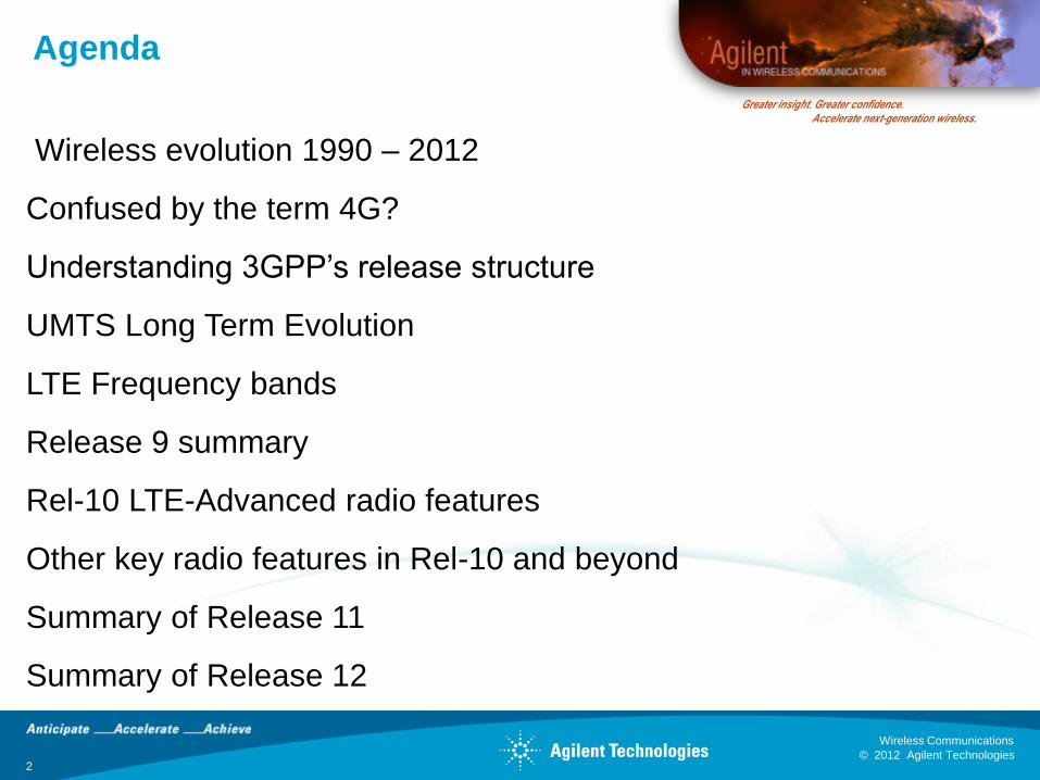
Agenda
Wireless evolution 1990 – 2012
Confused by the term 4G?
Understanding 3GPP’s release structure
UMTS Long Term Evolution
LTE Frequency bands
Release 9 summary
Rel-10 LTE-Advanced radio features
Other key radio features in Rel-10 and beyond
Summary of Release 11
Summary of Release 12
© 2012 Agilent Technologies
Wireless Communications
TD-SCDMA (China)
802.16e (Mobile WiMAX)
WiBRO (Korea)
802.16d (Fixed WiMAX)
802.11n
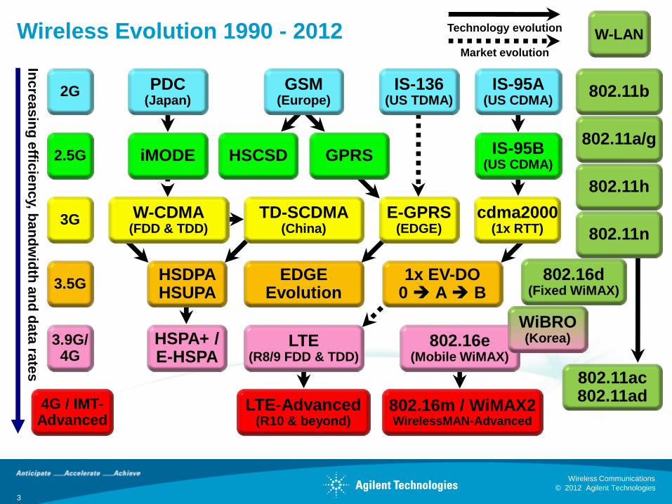
Wireless Evolution 1990 - 2012
GSM (Europe)
IS-136 (US TDMA)
PDC (Japan)
IS-95A (US CDMA)
HSCSD GPRS iMODE IS-95B (US CDMA)
W-CDMA (FDD & TDD)
E-GPRS (EDGE)
HSDPA HSUPA
EDGE Evolution
1x EV-DO 0 A B
HSPA+ / E-HSPA
LTE (R8/9 FDD & TDD)
LTE-Advanced (R10 & beyond)
802.16m / WiMAX2 WirelessMAN-Advanced
802.11h
802.11ac 802.11ad
cdma2000 (1x RTT)
802.11a/g
802.11b 2G
W-LAN
2.5G
3G
3.5G
3.9G/ 4G
4G / IMT-Advanced
Market evolution
Technology evolution
Inc
rea
sin
g e
fficie
nc
y, ba
nd
wid
th a
nd
da
ta ra
tes
3
© 2012 Agilent Technologies
Wireless Communications
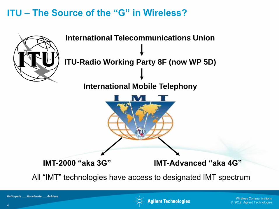
ITU – The Source of the “G” in Wireless?
International Mobile Telephony
International Telecommunications Union
ITU-Radio Working Party 8F (now WP 5D)
IMT-2000 “aka 3G” IMT-Advanced “aka 4G”
All “IMT” technologies have access to designated IMT spectrum
4
© 2012 Agilent Technologies
Wireless Communications
5 © 2012 Agilent Technologies
Wireless Communications
Greater insight. Greater confidence. Accelerate next-generation wireless.
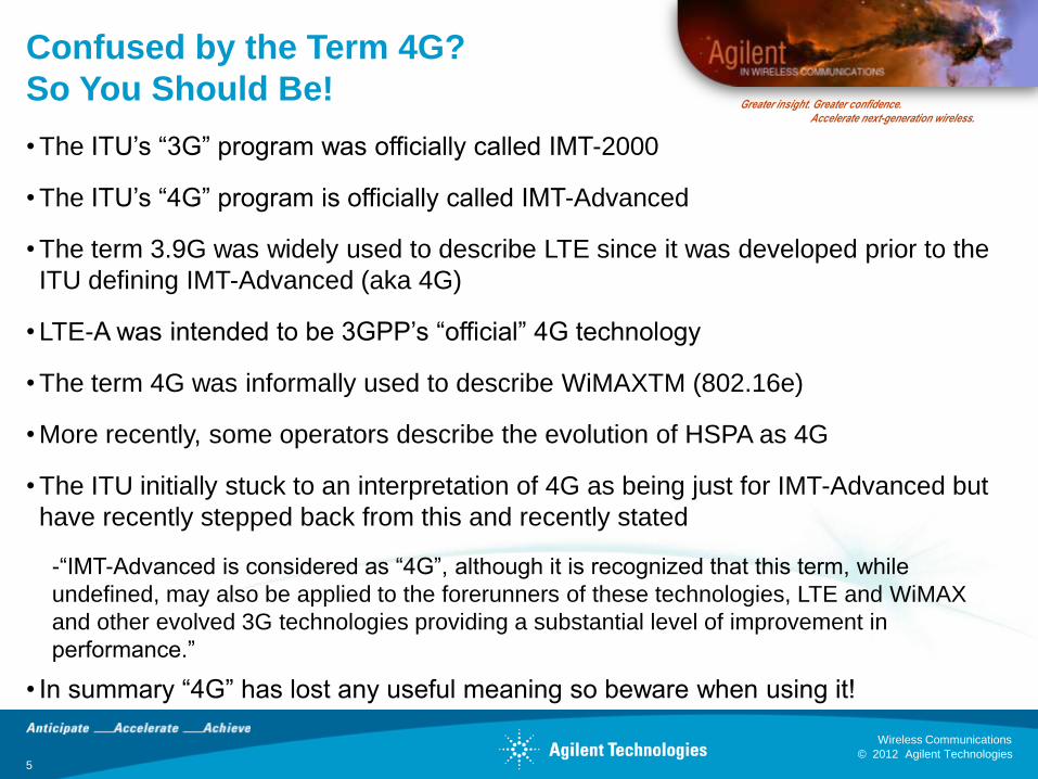
Confused by the Term 4G?
So You Should Be!
• The ITU’s “3G” program was officially called IMT-2000
• The ITU’s “4G” program is officially called IMT-Advanced
• The term 3.9G was widely used to describe LTE since it was developed prior to the
ITU defining IMT-Advanced (aka 4G)
• LTE-A was intended to be 3GPP’s “official” 4G technology
• The term 4G was informally used to describe WiMAXTM (802.16e)
• More recently, some operators describe the evolution of HSPA as 4G
• The ITU initially stuck to an interpretation of 4G as being just for IMT-Advanced but
have recently stepped back from this and recently stated
-“IMT-Advanced is considered as “4G”, although it is recognized that this term, while
undefined, may also be applied to the forerunners of these technologies, LTE and WiMAX
and other evolved 3G technologies providing a substantial level of improvement in
performance.”
• In summary “4G” has lost any useful meaning so beware when using it!
© 2012 Agilent Technologies
Wireless Communications
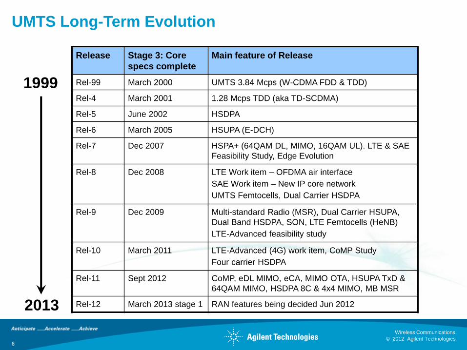
UMTS Long-Term Evolution
6
1999
2013
Release Stage 3: Core
specs complete
Main feature of Release
Rel-99 March 2000 UMTS 3.84 Mcps (W-CDMA FDD & TDD)
Rel-4 March 2001 1.28 Mcps TDD (aka TD-SCDMA)
Rel-5 June 2002 HSDPA
Rel-6 March 2005 HSUPA (E-DCH)
Rel-7 Dec 2007 HSPA+ (64QAM DL, MIMO, 16QAM UL). LTE & SAE
Feasibility Study, Edge Evolution
Rel-8 Dec 2008 LTE Work item – OFDMA air interface
SAE Work item – New IP core network
UMTS Femtocells, Dual Carrier HSDPA
Rel-9 Dec 2009 Multi-standard Radio (MSR), Dual Carrier HSUPA,
Dual Band HSDPA, SON, LTE Femtocells (HeNB)
LTE-Advanced feasibility study
Rel-10 March 2011 LTE-Advanced (4G) work item, CoMP Study
Four carrier HSDPA
Rel-11 Sept 2012 CoMP, eDL MIMO, eCA, MIMO OTA, HSUPA TxD &
64QAM MIMO, HSDPA 8C & 4x4 MIMO, MB MSR
Rel-12 March 2013 stage 1 RAN features being decided Jun 2012
© 2012 Agilent Technologies
Wireless Communications
7 © 2012 Agilent Technologies
Wireless Communications
Greater insight. Greater confidence. Accelerate next-generation wireless.
Frequency Bands
•An important aspect of frequency bands when it comes to the 3GPP
releases is that they are “release independent”
•This means that a band defined in a later release can be applied to
an earlier release.
•This significantly simplifies the specifications

© 2012 Agilent Technologies
Wireless Communications
8 © 2012 Agilent Technologies
Wireless Communications
Greater insight. Greater confidence. Accelerate next-generation wireless.
LTE FDD Frequency Bands Based on 36.101 Table 5.5-1 (March 2012)
Points of note
• There is a lot of overlap between
band definitions for regional reasons
• The Duplex spacing varies from 30
MHz to 799 MHz
• The gap between downlink and uplink
varies from 10 MHz to 680 MHz
• Narrow duplex spacing and gaps
make it hard to design filters to
prevent the transmitter spectral
regrowth leaking into the receiver
(self-blocking)
• Bands 13, 14, 20 and 24 are reversed
from normal by having the uplink
higher in frequency than the downlink
• Bands 15 and 16 are defined by ETSI
(not 3GPP) for Europe only – these
bands combine two nominally TDD
bands to create one FDD band
Uplink
Band
Downlink
Band
Gap
Duplex spacing
Width Width
Frequency Band Uplink MHz Downlink MHz Width Duplex Gap
1 1920 1980 2110 2170 60 190 130
2 1850 1910 1930 1990 60 80 20
3 1710 1785 1805 1880 75 95 20
4 1710 1755 2110 2155 45 400 355
5 824 849 869 894 25 45 20
6 830 840 865 875- 10 35 25
7 2500 2570 2620 2690 70 120 50
8 880 915 925 960 35 45 10
9 1749.9 1784.9 1844.9 1879.9 35 95 60
10 1710 1770 2110 2170 60 400 340
11 1427.9 1447.9 1475.9 1495.9 20 48 28
12 698 716 728 746 18 30 12
13 777 787 746 756 10 -31 41
14 788 798 758 768 10 -30 40
15* 1900 1920 2600 2620 20 700 680
16* 2010 2025 2585 2600 15 575 560
17 704 716 734 746 12 30 18
18 815 830 860 875 15 45 30
19 830 845 875 890 15 45 30
20 832 862 791 821 30 -41 71
21 1447.9 1462.9 1495.9 1510.9 15 48 33
22 3410 3490 3510 3590 80 100 20
23 2000 2020 2180 2200 20 180 160
24 1626.5 1660.5 1525 1559 34 -101.5 135.5
25 1850 1915 1930 1995 65 80 15
26 814 849 859 894 35 45 10
© 2012 Agilent Technologies
Wireless Communications
9 © 2012 Agilent Technologies
Wireless Communications
Greater insight. Greater confidence. Accelerate next-generation wireless.
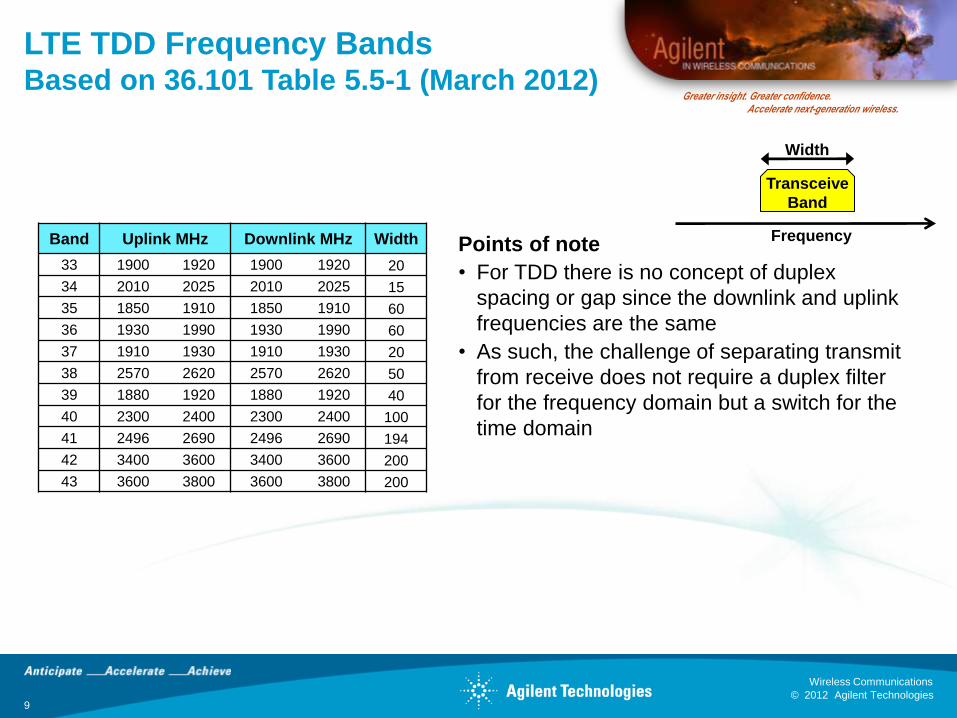
LTE TDD Frequency Bands Based on 36.101 Table 5.5-1 (March 2012)
Points of note
• For TDD there is no concept of duplex
spacing or gap since the downlink and uplink
frequencies are the same
• As such, the challenge of separating transmit
from receive does not require a duplex filter
for the frequency domain but a switch for the
time domain
Band Uplink MHz Downlink MHz Width
33 1900 1920 1900 1920 20
34 2010 2025 2010 2025 15
35 1850 1910 1850 1910 60
36 1930 1990 1930 1990 60
37 1910 1930 1910 1930 20
38 2570 2620 2570 2620 50
39 1880 1920 1880 1920 40
40 2300 2400 2300 2400 100
41 2496 2690 2496 2690 194
42 3400 3600 3400 3600 200
43 3600 3800 3600 3800 200
Transceive
Band
Width
Frequency
© 2012 Agilent Technologies
Wireless Communications
10 © 2012 Agilent Technologies
Wireless Communications
Greater insight. Greater confidence. Accelerate next-generation wireless.
Future LTE/UTRA Frequency Bands
•The work on defining new frequency bands continues. Currently being
considered by 3GPP:
•Band 27 806/824 + 851/869 – Extended 850 lower band
•Other possibilities identified by the ITU:
•3.6-4.2 GHz
•450−470 MHz
•698−862 MHz
•790−862 MHz band (European digital dividend)
•4.4-4.99 GHz band
© 2012 Agilent Technologies
Wireless Communications
11 © 2012 Agilent Technologies
Wireless Communications
Greater insight. Greater confidence. Accelerate next-generation wireless.
Release 9 Summary
•Release 9 adds many small features to UMTS and LTE e.g.:
– Completion of MBSFN
– New frequency bands
– Transmission mode 8 (dual stream beamforming)
– Positioning Reference Signal (PRS) for Observed Time Difference Of Arrival
(OTDOA) positioning
•The most significant radio feature is Multi-Standard Radio (MSR) for BS that
support more than one radio format
•MSR is a don’t care for the UE but is a big deal for the BS
•The work involved harmonizing the GERAN and 3GPP specifications then
specifying common requirements and conformance tests
•Multi-band MSR is being added in Release 11
© 2012 Agilent Technologies
Wireless Communications
12 © 2012 Agilent Technologies
Wireless Communications
Greater insight. Greater confidence. Accelerate next-generation wireless.
Update on LTE-Advanced
Overall Aspects
•LTE-Advanced is a subset of Release 10
•A comprehensive summary of the entire LTE-Advanced proposals including radio, network and system can be found in the 3GPP submissions to the first IMT-Advanced evaluation workshop.
http://www.3gpp.org/ftp/workshop/2009-12-17_ITU-R_IMT-Adv_eval/docs/
•The remainder of this presentation will focus on the key radio aspects
© 2012 Agilent Technologies
Wireless Communications
13 © 2012 Agilent Technologies
Wireless Communications
Greater insight. Greater confidence. Accelerate next-generation wireless.
LTE-Advanced Requirements & Proposals
•LTE-A requirements are documented in TR 36.913, V9.0.0 (2009-03)
(Requirements for Further Advancements of E-UTRA (LTE-Advanced)
•3GPP stated intention is to meet or exceed IMT-Advanced requirements
•LTE-A must support IMT-A requirements with same or better performance
than LTE
•LTE-A solution proposals can be found in TR 36.814 – “Further
Advancements for E-UTRA Physical Layer Aspects”
•Specific targets exist for average and cell-edge spectral efficiency (see next
slide)
•Similar requirements as LTE for synchronization, latency, coverage,
mobility…
•LTE-A candidate was submitted to ITU September 2009 and formally
approved in Jan 2012
© 2012 Agilent Technologies
Wireless Communications
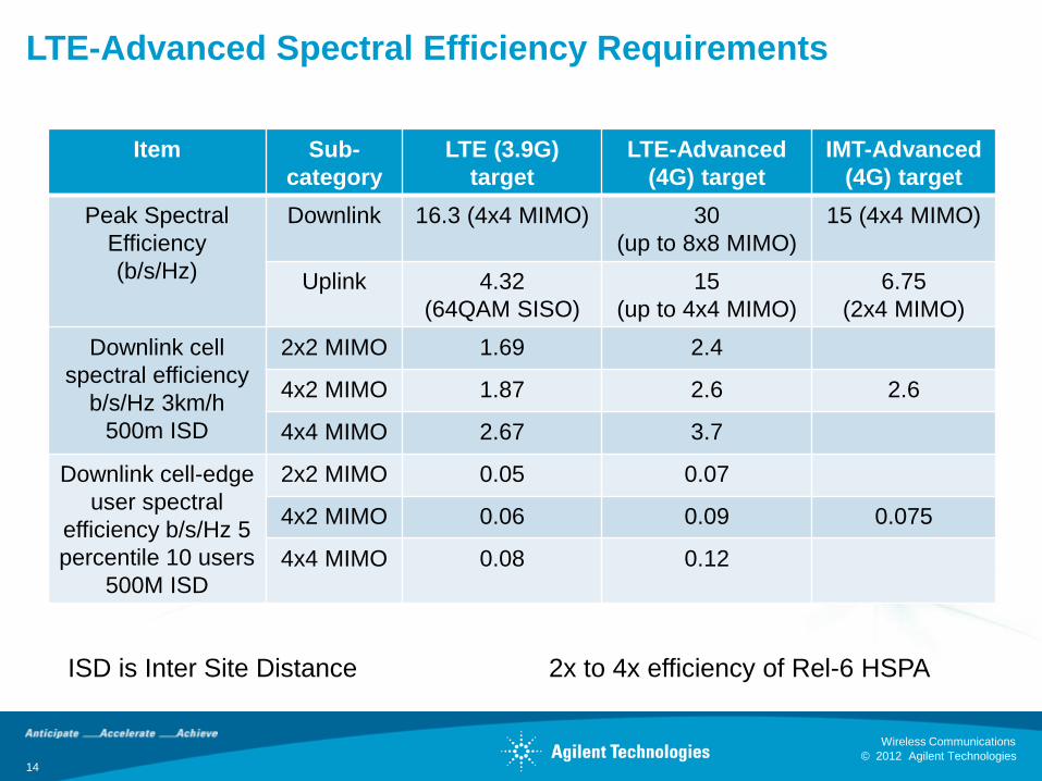
LTE-Advanced Spectral Efficiency Requirements
Item Sub-
category
LTE (3.9G)
target
LTE-Advanced
(4G) target
IMT-Advanced
(4G) target
Peak Spectral
Efficiency
(b/s/Hz)
Downlink 16.3 (4x4 MIMO) 30
(up to 8x8 MIMO)
15 (4x4 MIMO)
Uplink 4.32
(64QAM SISO)
15
(up to 4x4 MIMO)
6.75
(2x4 MIMO)
Downlink cell
spectral efficiency
b/s/Hz 3km/h
500m ISD
2x2 MIMO 1.69 2.4
4x2 MIMO 1.87 2.6 2.6
4x4 MIMO 2.67 3.7
Downlink cell-edge
user spectral
efficiency b/s/Hz 5
percentile 10 users
500M ISD
2x2 MIMO 0.05 0.07
4x2 MIMO 0.06 0.09 0.075
4x4 MIMO 0.08 0.12
ISD is Inter Site Distance 2x to 4x efficiency of Rel-6 HSPA
14
© 2012 Agilent Technologies
Wireless Communications
15 © 2012 Agilent Technologies
Wireless Communications
Greater insight. Greater confidence. Accelerate next-generation wireless.
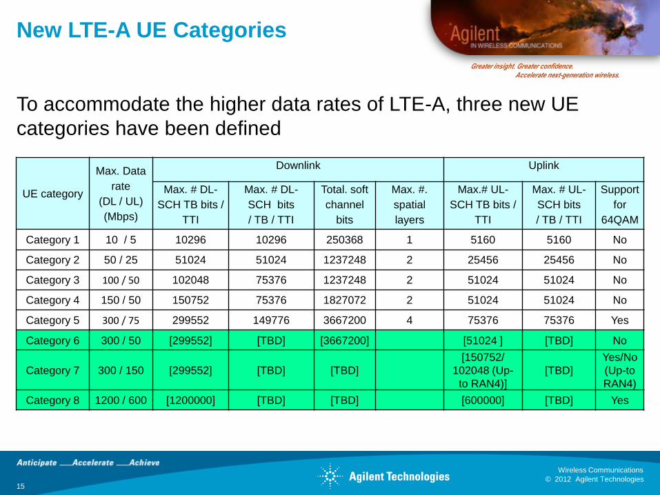
New LTE-A UE Categories
To accommodate the higher data rates of LTE-A, three new UE
categories have been defined
UE category
Max. Data
rate
(DL / UL)
(Mbps)
Downlink Uplink
Max. # DL-
SCH TB bits /
TTI
Max. # DL-
SCH bits
/ TB / TTI
Total. soft
channel
bits
Max. #.
spatial
layers
Max.# UL-
SCH TB bits /
TTI
Max. # UL-
SCH bits
/ TB / TTI
Support
for
64QAM
Category 1 10 / 5 10296 10296 250368 1 5160 5160 No
Category 2 50 / 25 51024 51024 1237248 2 25456 25456 No
Category 3 100 / 50 102048 75376 1237248 2 51024 51024 No
Category 4 150 / 50 150752 75376 1827072 2 51024 51024 No
Category 5 300 / 75 299552 149776 3667200 4 75376 75376 Yes
Category 6 300 / 50 [299552] [TBD] [3667200] [51024 ] [TBD] No
Category 7 300 / 150 [299552] [TBD] [TBD]
[150752/
102048 (Up-
to RAN4)]
[TBD]
Yes/No
(Up-to
RAN4)
Category 8 1200 / 600 [1200000] [TBD] [TBD] [600000] [TBD] Yes
© 2012 Agilent Technologies
Wireless Communications
16 © 2012 Agilent Technologies
Wireless Communications
Greater insight. Greater confidence. Accelerate next-generation wireless.
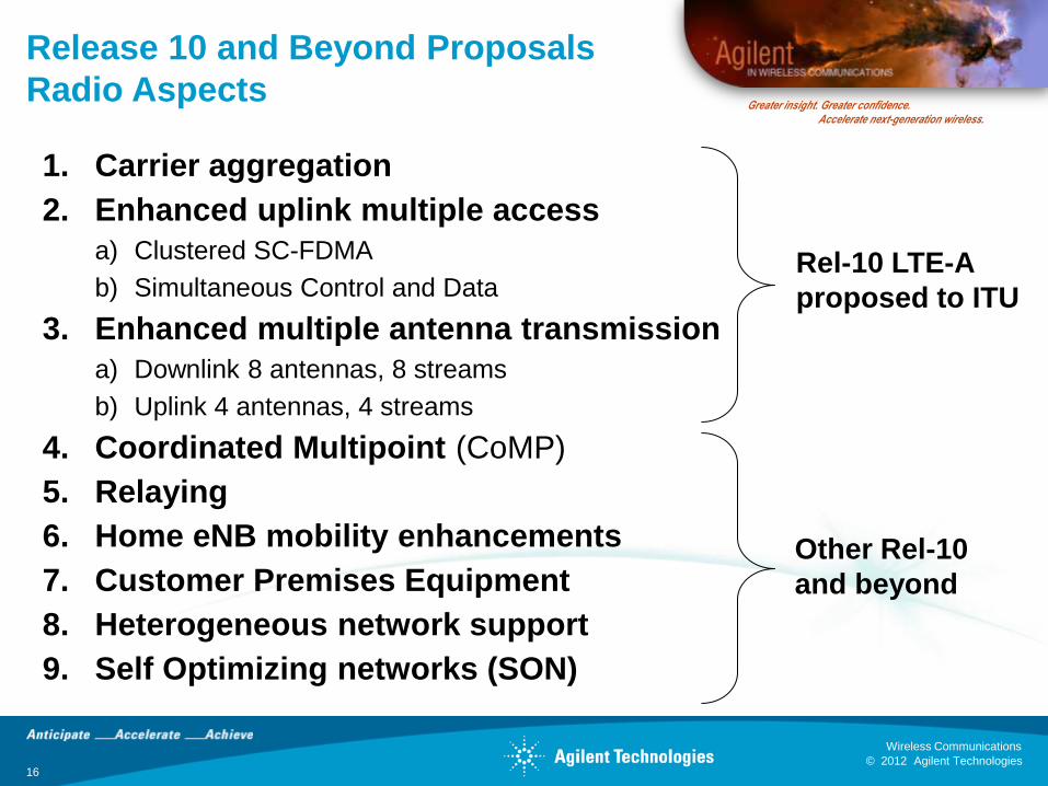
Release 10 and Beyond Proposals
Radio Aspects
1. Carrier aggregation
2. Enhanced uplink multiple access
a) Clustered SC-FDMA
b) Simultaneous Control and Data
3. Enhanced multiple antenna transmission
a) Downlink 8 antennas, 8 streams
b) Uplink 4 antennas, 4 streams
4. Coordinated Multipoint (CoMP)
5. Relaying
6. Home eNB mobility enhancements
7. Customer Premises Equipment
8. Heterogeneous network support
9. Self Optimizing networks (SON)
Rel-10 LTE-A
proposed to ITU
Other Rel-10
and beyond
© 2012 Agilent Technologies
Wireless Communications
MHz
1.4
3
5
10
15
20
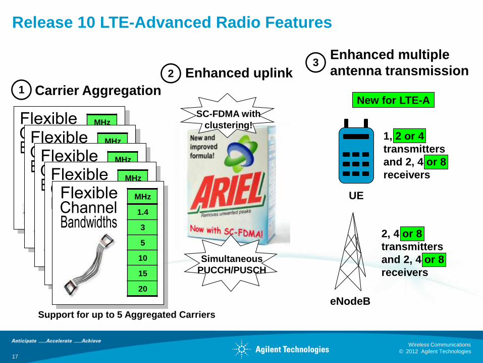
Support for up to 5 Aggregated Carriers
MHz
1.4
3
5
10
15
20
MHz
1.4
3
5
10
15
20
MHz
1.4
3
5
10
15
20
MHz
1.4
3
5
10
15
20
SC-FDMA with
clustering!
Release 10 LTE-Advanced Radio Features
1 Carrier Aggregation
2 Enhanced uplink 3
Enhanced multiple
antenna transmission
Simultaneous
PUCCH/PUSCH
UE
eNodeB
1, 2 or 4
transmitters
and 2, 4 or 8
receivers
2, 4 or 8
transmitters
and 2, 4 or 8
receivers
New for LTE-A
17
© 2012 Agilent Technologies
Wireless Communications
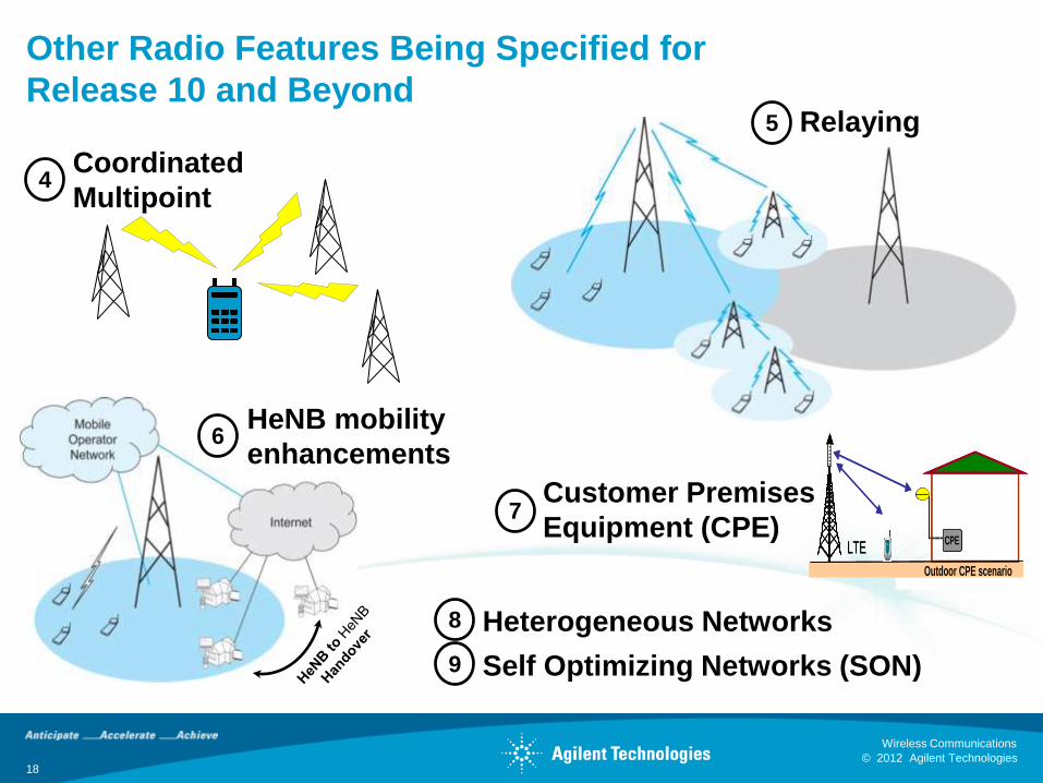
Other Radio Features Being Specified for
Release 10 and Beyond
4 Coordinated
Multipoint
5 Relaying
8 Heterogeneous Networks
9 Self Optimizing Networks (SON)
7 Customer Premises
Equipment (CPE) CPE
LTECPE
LTE
Indoor CPE scenario Outdoor CPE scenario
CPELTE
CPELTE
Indoor CPE scenario Outdoor CPE scenario
6 HeNB mobility
enhancements
18
© 2012 Agilent Technologies
Wireless Communications
19 © 2012 Agilent Technologies
Wireless Communications
Greater insight. Greater confidence. Accelerate next-generation wireless.
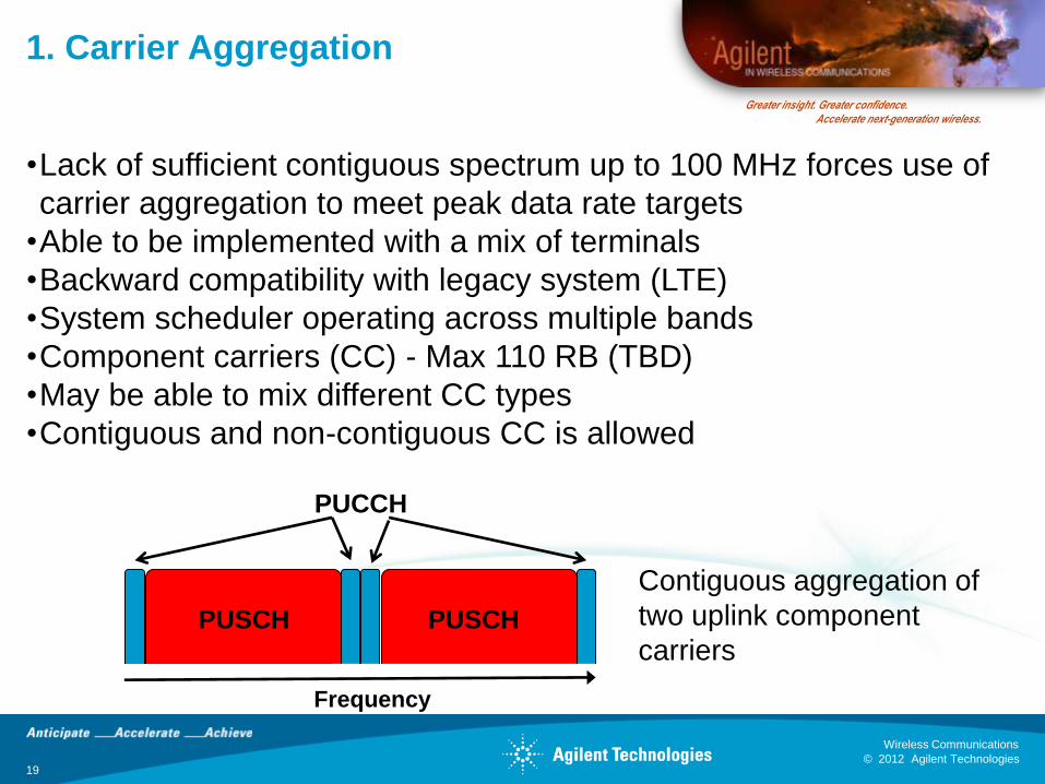
1. Carrier Aggregation
•Lack of sufficient contiguous spectrum up to 100 MHz forces use of
carrier aggregation to meet peak data rate targets
•Able to be implemented with a mix of terminals
•Backward compatibility with legacy system (LTE)
•System scheduler operating across multiple bands
•Component carriers (CC) - Max 110 RB (TBD)
•May be able to mix different CC types
•Contiguous and non-contiguous CC is allowed
Contiguous aggregation of
two uplink component
carriers PUSCH PUSCH
PUCCH
Frequency
© 2012 Agilent Technologies
Wireless Communications
20 © 2012 Agilent Technologies
Wireless Communications
Greater insight. Greater confidence. Accelerate next-generation wireless.
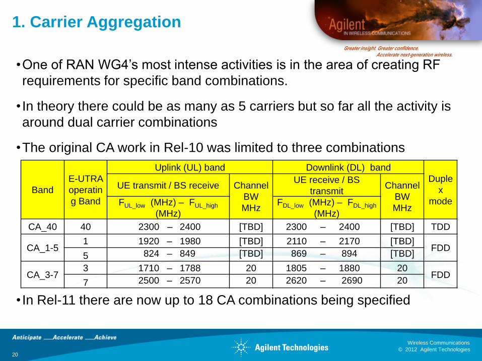
1. Carrier Aggregation
Band
E-UTRA
operatin
g Band
Uplink (UL) band Downlink (DL) band
Duple
x
mode
UE transmit / BS receive Channel
BW
MHz
UE receive / BS
transmit Channel
BW
MHz FUL_low (MHz) – FUL_high
(MHz)
FDL_low (MHz) – FDL_high
(MHz)
CA_40 40 2300 – 2400 [TBD] 2300 – 2400 [TBD] TDD
CA_1-5 1 1920 – 1980 [TBD] 2110 – 2170 [TBD]
FDD 5 824 – 849 [TBD] 869 – 894 [TBD]
CA_3-7 3 1710 – 1788 20 1805 – 1880 20
FDD 7 2500 – 2570 20 2620 – 2690 20
•One of RAN WG4’s most intense activities is in the area of creating RF
requirements for specific band combinations.
• In theory there could be as many as 5 carriers but so far all the activity is
around dual carrier combinations
•The original CA work in Rel-10 was limited to three combinations
• In Rel-11 there are now up to 18 CA combinations being specified

© 2012 Agilent Technologies
Wireless Communications
21 © 2012 Agilent Technologies
Wireless Communications
Greater insight. Greater confidence. Accelerate next-generation wireless.
1. Carrier Aggregation Design and Test
Challenges
•Not such an issue for the eNB
•Major challenge for the UE
– Multiple simultaneous receive chains
– Multiple simultaneous transmit chains
•Simultaneous non-contiguous transmitters creates a very challenging
radio environment in terms of spur management and self-blocking
•Simultaneous transmit or receive with mandatory MIMO support add
significantly to the challenge of antenna design
© 2012 Agilent Technologies
Wireless Communications
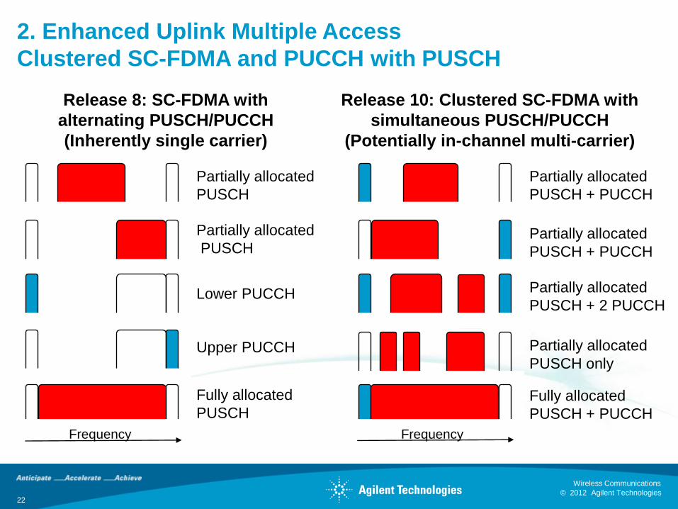
2. Enhanced Uplink Multiple Access
Clustered SC-FDMA and PUCCH with PUSCH
Release 8: SC-FDMA with
alternating PUSCH/PUCCH
(Inherently single carrier)
Release 10: Clustered SC-FDMA with
simultaneous PUSCH/PUCCH
(Potentially in-channel multi-carrier)
Partially allocated
PUSCH
Partially allocated
PUSCH
Upper PUCCH
Fully allocated
PUSCH
Lower PUCCH
Partially allocated
PUSCH + PUCCH
Partially allocated
PUSCH + PUCCH
Partially allocated
PUSCH + 2 PUCCH
Partially allocated
PUSCH only
Fully allocated
PUSCH + PUCCH
Frequency Frequency
22
© 2012 Agilent Technologies
Wireless Communications
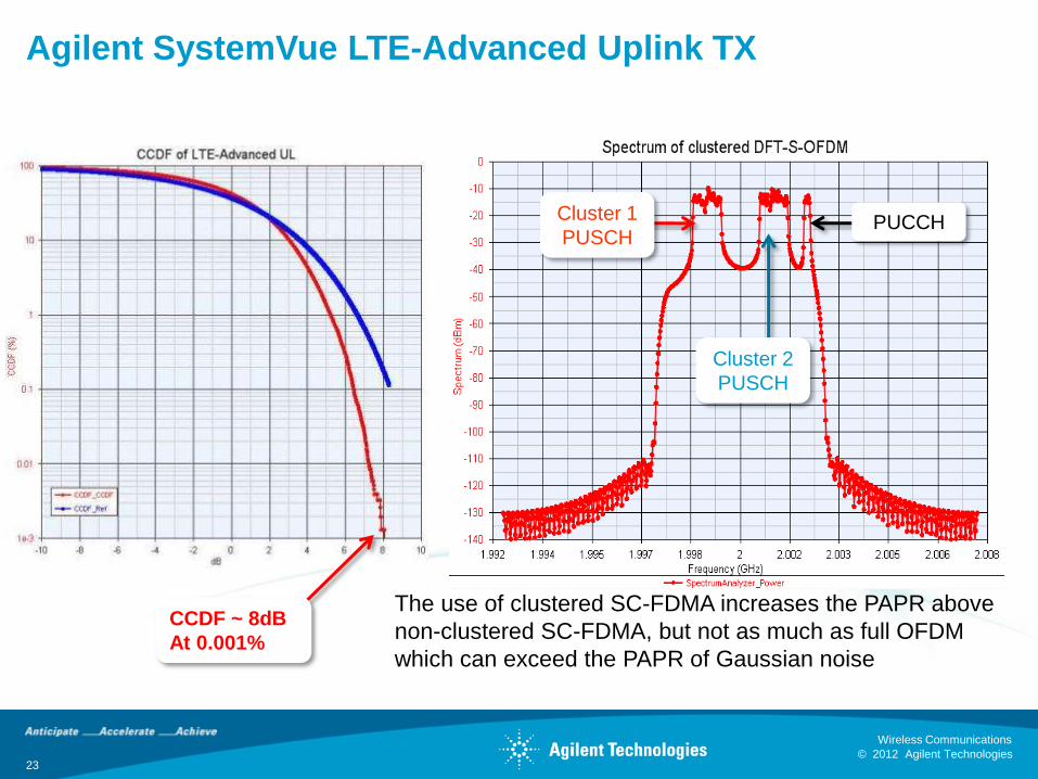
Agilent SystemVue LTE-Advanced Uplink TX
Cluster 1
PUSCH PUCCH
Cluster 2
PUSCH
CCDF ~ 8dB
At 0.001%
The use of clustered SC-FDMA increases the PAPR above
non-clustered SC-FDMA, but not as much as full OFDM
which can exceed the PAPR of Gaussian noise
23

© 2012 Agilent Technologies
Wireless Communications
24 © 2012 Agilent Technologies
Wireless Communications
Greater insight. Greater confidence. Accelerate next-generation wireless.
2. Enhanced Uplink Multiple Access
Design and Test Challenges
•Clustered SC-FDMA increases PAR by a few dB adding to transmitter linearity challenges
•Simultaneous PUCCH and PUSCH also increases PAR
•Both feature create multi-carrier signals within the channel bandwidth
•High power narrow PUCCH plus single or clustered SC-FDMA creates large opportunity for in-channel and adjacent channel spur generation
– May require 3 to 4 dB power amp backoff for Rel-8 PA
– Some scenarios may require 10 dB backoff
•Due to the spur issues the status of the enhanced uplink is still to be decided for Release 10
© 2012 Agilent Technologies
Wireless Communications
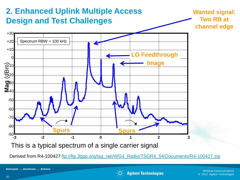
2. Enhanced Uplink Multiple Access
Design and Test Challenges
Derived from R4-100427 ftp://ftp.3gpp.org/tsg_ran/WG4_Radio/TSGR4_54/Documents/R4-100427.zip
This is a typical spectrum of a single carrier signal
+30
+20
+10
0
-10
-20
-30
-40
-50
-60
-70
-80
-90
Mag
(dB
m)
-3 -2 -1 0 1 2 3
Spectrum RBW = 100 kHz
LO Feedthrough
Image
Spurs Spurs
Wanted signal:
Two RB at
channel edge
25
© 2012 Agilent Technologies
Wireless Communications
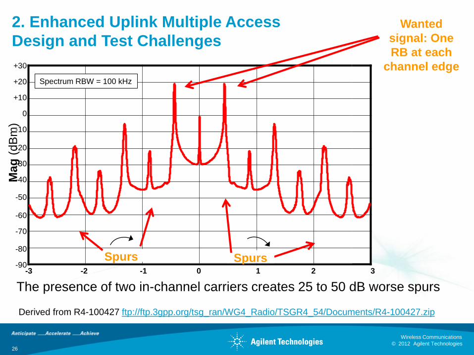
2. Enhanced Uplink Multiple Access
Design and Test Challenges
Derived from R4-100427 ftp://ftp.3gpp.org/tsg_ran/WG4_Radio/TSGR4_54/Documents/R4-100427.zip
The presence of two in-channel carriers creates 25 to 50 dB worse spurs
+30
+20
+10
0
-10
-20
-30
-40
-50
-60
-70
-80
-90
Mag
(dB
m)
-3 -2 -1 0 1 2 3
Spectrum RBW = 100 kHz
Wanted
signal: One
RB at each
channel edge
Spurs Spurs
26
© 2012 Agilent Technologies
Wireless Communications
27 © 2012 Agilent Technologies
Wireless Communications
Greater insight. Greater confidence. Accelerate next-generation wireless.
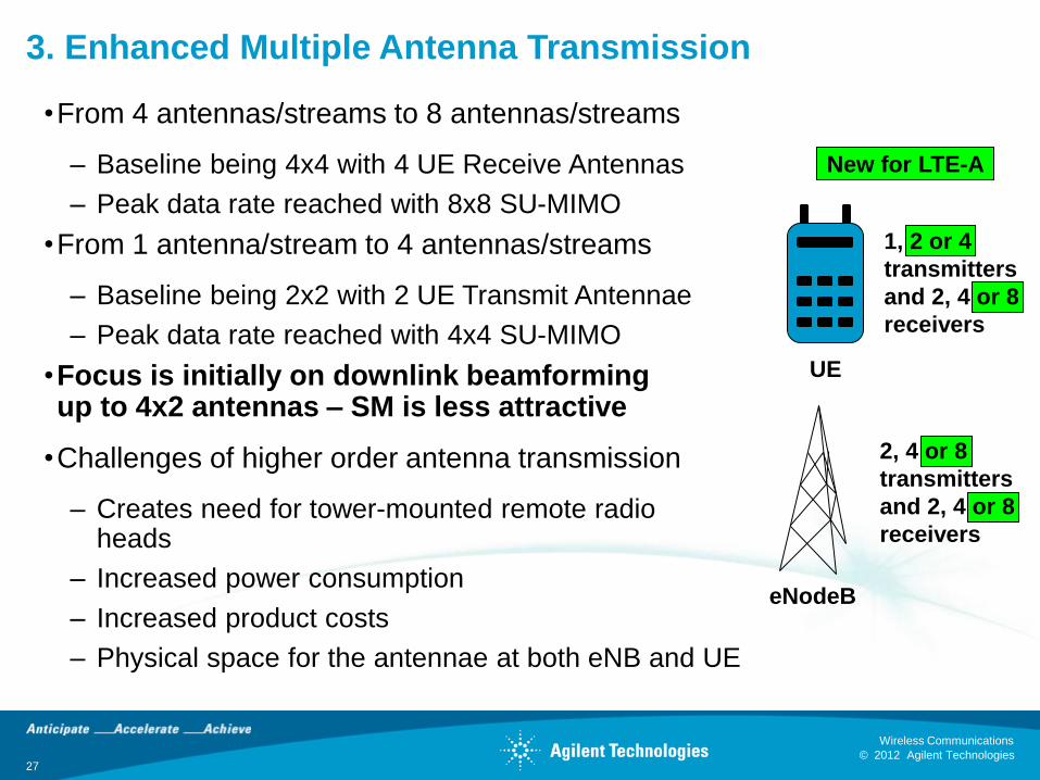
3. Enhanced Multiple Antenna Transmission
•From 4 antennas/streams to 8 antennas/streams
– Baseline being 4x4 with 4 UE Receive Antennas
– Peak data rate reached with 8x8 SU-MIMO
•From 1 antenna/stream to 4 antennas/streams
– Baseline being 2x2 with 2 UE Transmit Antennae
– Peak data rate reached with 4x4 SU-MIMO
•Focus is initially on downlink beamforming up to 4x2 antennas – SM is less attractive
•Challenges of higher order antenna transmission
– Creates need for tower-mounted remote radio heads
– Increased power consumption
– Increased product costs
– Physical space for the antennae at both eNB and UE
UE
eNodeB
1, 2 or 4
transmitters
and 2, 4 or 8
receivers
2, 4 or 8
transmitters
and 2, 4 or 8
receivers
New for LTE-A
© 2012 Agilent Technologies
Wireless Communications
28 © 2012 Agilent Technologies
Wireless Communications
Greater insight. Greater confidence. Accelerate next-generation wireless.
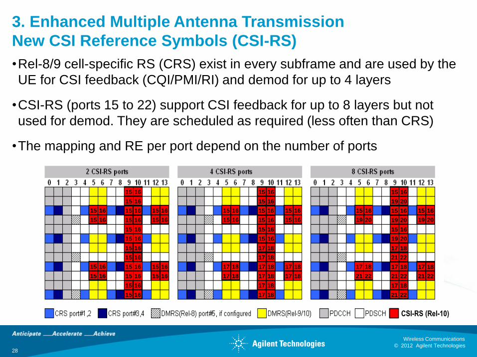
3. Enhanced Multiple Antenna Transmission
New CSI Reference Symbols (CSI-RS)
•Rel-8/9 cell-specific RS (CRS) exist in every subframe and are used by the
UE for CSI feedback (CQI/PMI/RI) and demod for up to 4 layers
•CSI-RS (ports 15 to 22) support CSI feedback for up to 8 layers but not
used for demod. They are scheduled as required (less often than CRS)
•The mapping and RE per port depend on the number of ports
15 16
15 16
15 16
15 16
15 16
15 16
15 16
15 16
15 16
15 16
15 16
15 16
15 16
15 16
15 16
15 16
15 16
15 16
15 16
15 16
15 16
15 16
15 16
15 16
17 18
17 18
17 18
17 18
17 18
17 18
17 18
17 18
15 16
15 16
15 16
15 16
15 16
15 16
15 16
15 16
15 16
15 16
17 18
17 18
17 18
21 22
17 18
21 22
17 18
21 22
17 18
21 22
15 16
19 20
15 16
19 20
15 16
19 20
15 16
19 20
15 16
19 20
17 18
21 22
CSI-RS (Rel-10)
© 2012 Agilent Technologies
Wireless Communications
29 © 2012 Agilent Technologies
Wireless Communications
Greater insight. Greater confidence. Accelerate next-generation wireless.
3. Enhanced Multiple Antenna Transmission
Design and Test Challenges
•Higher order MIMO has a similar impact on the need for simultaneous transceivers as does carrier aggregation
•However, there is an additional challenge in that the antennas also have to multiply in number
•MIMO antennas also require to be de-correlated
•It is very hard to design a multi-band, MIMO antenna in a small space with good de-correlation
•This makes conducted testing of higher order MIMO terminals largely irrelevant in predicting the actual radiated performance in an operational network
•There is a work item in Rel-11 looking at MIMO Over the Air (OTA) testing which will address antenna performance
© 2012 Agilent Technologies
Wireless Communications
30 © 2012 Agilent Technologies
Wireless Communications
Greater insight. Greater confidence. Accelerate next-generation wireless.
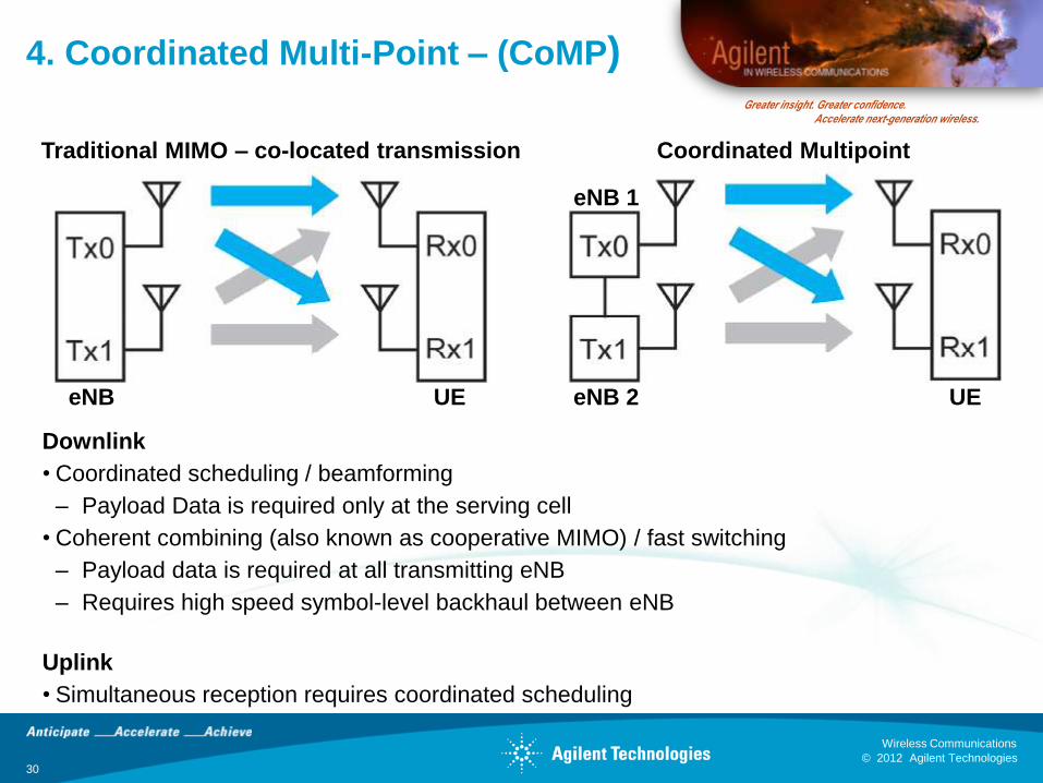
4. Coordinated Multi-Point – (CoMP)
Downlink
• Coordinated scheduling / beamforming
– Payload Data is required only at the serving cell
• Coherent combining (also known as cooperative MIMO) / fast switching
– Payload data is required at all transmitting eNB
– Requires high speed symbol-level backhaul between eNB
Uplink
• Simultaneous reception requires coordinated scheduling
Traditional MIMO – co-located transmission Coordinated Multipoint
eNB eNB 2
eNB 1
UE UE
© 2012 Agilent Technologies
Wireless Communications
31 © 2012 Agilent Technologies
Wireless Communications
Greater insight. Greater confidence. Accelerate next-generation wireless.
4. CoMP Status
•Recent simulation by RAN WG1 has shown initial CoMP performance
improvement to be in the 5% to 15% range
•This is not considered sufficient to progress this aspect of the proposals
within the Rel-10 timeframe
•Recent results from the EASY-C testbed also show limited performance
gains in lightly loaded networks with minimal or no interference
•CoMP is now being studied further for Release 11
• It remains unclear what eNB testing of CoMP might entail since it is very
much a system level performance gain and very difficult to emulate
© 2012 Agilent Technologies
Wireless Communications
32 © 2012 Agilent Technologies
Wireless Communications
Greater insight. Greater confidence. Accelerate next-generation wireless.
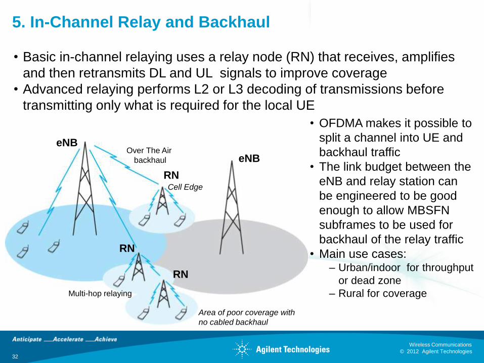
5. In-Channel Relay and Backhaul
• Basic in-channel relaying uses a relay node (RN) that receives, amplifies
and then retransmits DL and UL signals to improve coverage
• Advanced relaying performs L2 or L3 decoding of transmissions before
transmitting only what is required for the local UE
Cell Edge
Area of poor coverage with
no cabled backhaul
Multi-hop relaying
Over The Air
backhaul
• OFDMA makes it possible to
split a channel into UE and
backhaul traffic
• The link budget between the
eNB and relay station can
be engineered to be good
enough to allow MBSFN
subframes to be used for
backhaul of the relay traffic
• Main use cases: – Urban/indoor for throughput
or dead zone
– Rural for coverage
eNB
eNB
RN
RN
RN
© 2012 Agilent Technologies
Wireless Communications
33 © 2012 Agilent Technologies
Wireless Communications
Greater insight. Greater confidence. Accelerate next-generation wireless.
5. In-Channel Relay and Backhaul
Design and Test Challenges
•From the UE perspective, Relaying is completely transparent
•The challenge is all on the network side
•For the system to work, the link budget from the relay node to the macro eNB must be good
– This implies line of sight positioning
•The main operational challenge with getting relaying to work will be in the management of the UE
– The UE has to hand over to the relay node when in range
– It must release the relay node when out of range
• If this process is not well-managed, the performance of the cell could go down not up
•Multi-hop relaying for coverage should be easier
– e.g. a valley with no cabled backhaul
© 2012 Agilent Technologies
Wireless Communications
34 © 2012 Agilent Technologies
Wireless Communications
Greater insight. Greater confidence. Accelerate next-generation wireless.
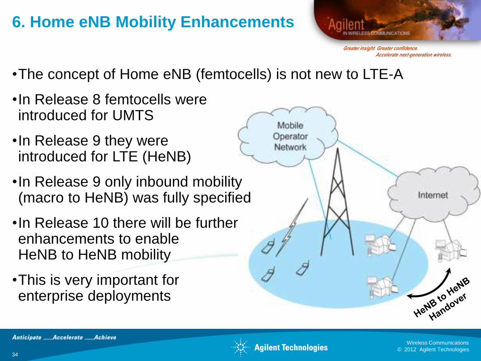
6. Home eNB Mobility Enhancements
•The concept of Home eNB (femtocells) is not new to LTE-A
•In Release 8 femtocells were introduced for UMTS
•In Release 9 they were introduced for LTE (HeNB)
•In Release 9 only inbound mobility (macro to HeNB) was fully specified
•In Release 10 there will be further enhancements to enable HeNB to HeNB mobility
•This is very important for enterprise deployments

© 2012 Agilent Technologies
Wireless Communications
35 © 2012 Agilent Technologies
Wireless Communications
Greater insight. Greater confidence. Accelerate next-generation wireless.
7. Customer Premises Equipment (CPE)
•The CPE is a “mobile” intended for fixed (indoor) operation
•The antenna may be internal (omni) or external (directional)
•The max output power is increased to 27 dBm
•Lack of concern for power consumption and a better radio link
budget mean the CPE can deliver much higher performance e.g. For
rural broadband applications
CPELTE
CPELTE
Indoor CPE scenario Outdoor CPE scenario
CPELTE
CPELTE
Indoor CPE scenario Outdoor CPE scenario

© 2012 Agilent Technologies
Wireless Communications
36 © 2012 Agilent Technologies
Wireless Communications
Greater insight. Greater confidence. Accelerate next-generation wireless.
8. Heterogeneous Network Support
•LTE-Advanced intends to address the support needs of
heterogeneous networks that combine low power nodes (such as
picocells, femtocells, repeaters, and relay nodes) within a macrocell.
•Deployment scenarios under evaluation are detailed in TR 36.814
Annex A.
© 2012 Agilent Technologies
Wireless Communications
37 © 2012 Agilent Technologies
Wireless Communications
Greater insight. Greater confidence. Accelerate next-generation wireless.
9. Self Optimizing Networks (SON)
•Today’s cellular systems are very much centrally planned, and the
addition of new nodes to the network involves expensive and time-
consuming work, site visits for optimization, and other deployment
challenges.
•One of the enhancements being considered for LTE-Advanced is the
self-optimizing network (SON).
•The intent is to substantially reduce the effort required to introduce
new nodes to the network. There are implications for radio planning
as well as for the operations and maintenance (O&M) interface to the
base station.
•Some limited SON capability was introduced in Release 8 and is
being further elaborated in Release 9 and Release 10.
© 2012 Agilent Technologies
Wireless Communications
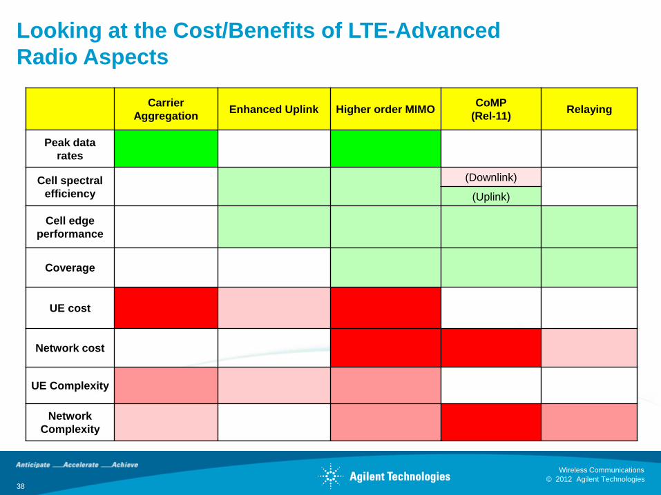
Looking at the Cost/Benefits of LTE-Advanced
Radio Aspects
Carrier
Aggregation Enhanced Uplink Higher order MIMO
CoMP
(Rel-11) Relaying
Peak data
rates
Cell spectral
efficiency
(Downlink)
(Uplink)
Cell edge
performance
Coverage
UE cost
Network cost
UE Complexity
Network
Complexity
38
© 2012 Agilent Technologies
Wireless Communications
39 © 2012 Agilent Technologies
Wireless Communications
Greater insight. Greater confidence. Accelerate next-generation wireless.
LTE-A Deployment
•The first question to ask when people are looking form information on
LTE-A timing is “which feature”
•LTE-A, Release 10 etc. Is a large grouping of backwards-compatible
features, none of which are mandatory
•The most likely contenders for early LTE-A deployment are:
•Some limited form of carrier aggregation to increase instantaneous
bandwidth is particular local operator areas
– E.g. US operator combining 10 MHz at 700 with 10 MHz at 1700
– Expensive requires two transceivers unless adjacent
•Uplink MIMO
– Requires two UE transmitters – expensive, battery issues
•Enhanced downlink e.g. 8x2
© 2012 Agilent Technologies
Wireless Communications
40 © 2012 Agilent Technologies
Wireless Communications
Greater insight. Greater confidence. Accelerate next-generation wireless.
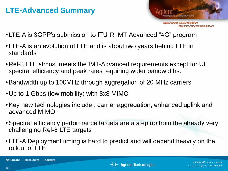
LTE-Advanced Summary
•LTE-A is 3GPP’s submission to ITU-R IMT-Advanced “4G” program
•LTE-A is an evolution of LTE and is about two years behind LTE in standards
•Rel-8 LTE almost meets the IMT-Advanced requirements except for UL spectral efficiency and peak rates requiring wider bandwidths.
•Bandwidth up to 100MHz through aggregation of 20 MHz carriers
•Up to 1 Gbps (low mobility) with 8x8 MIMO
•Key new technologies include : carrier aggregation, enhanced uplink and advanced MIMO
•Spectral efficiency performance targets are a step up from the already very challenging Rel-8 LTE targets
•LTE-A Deployment timing is hard to predict and will depend heavily on the rollout of LTE
© 2012 Agilent Technologies
Wireless Communications
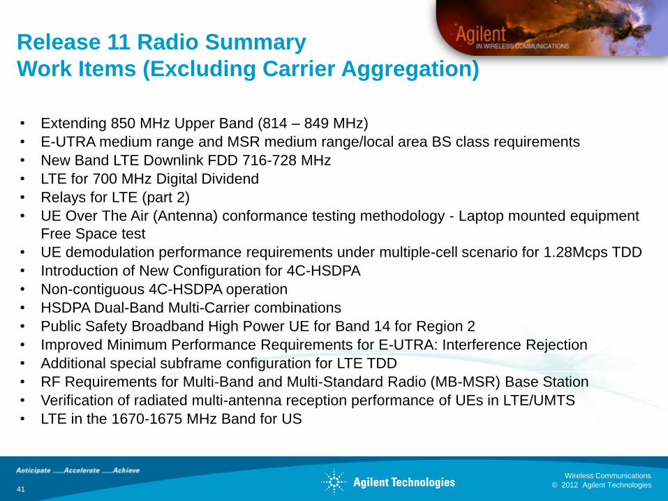
Release 11 Radio Summary
Work Items (Excluding Carrier Aggregation)
• Extending 850 MHz Upper Band (814 – 849 MHz)
• E-UTRA medium range and MSR medium range/local area BS class requirements
• New Band LTE Downlink FDD 716-728 MHz
• LTE for 700 MHz Digital Dividend
• Relays for LTE (part 2)
• UE Over The Air (Antenna) conformance testing methodology - Laptop mounted equipment
Free Space test
• UE demodulation performance requirements under multiple-cell scenario for 1.28Mcps TDD
• Introduction of New Configuration for 4C-HSDPA
• Non-contiguous 4C-HSDPA operation
• HSDPA Dual-Band Multi-Carrier combinations
• Public Safety Broadband High Power UE for Band 14 for Region 2
• Improved Minimum Performance Requirements for E-UTRA: Interference Rejection
• Additional special subframe configuration for LTE TDD
• RF Requirements for Multi-Band and Multi-Standard Radio (MB-MSR) Base Station
• Verification of radiated multi-antenna reception performance of UEs in LTE/UMTS
• LTE in the 1670-1675 MHz Band for US
41

© 2012 Agilent Technologies
Wireless Communications
Release 11 Radio Summary
Study Items
• Study on Inclusion of RF Pattern Matching Technologies as a positioning method in the E-
UTRAN
• Study on Interference analysis between 800~900 MHz bands
• Study on Enhanced performance requirement for LTE UE
• Study on Measurement of Radiated Performance for MIMO and multi-antenna reception
for HSPA and LTE terminals
• Study on Extending 850 MHz
• Study on UMTS/LTE in 900 MHz band (Japan, Korea)
• Study on RF and EMC requirements for active Antenna Array System (AAS) Base Station
• Study on UE Over The Air (OTA) test method with Head and Hand Phantoms
• Study on Passive InterModulation (PIM) handling for UTRA and LTE Base Stations
• Study on Measurements of radio performances for LTE terminals - Total Radiated Power
(TRP) and Total Radiated Sensitivity (TRS) test methodology
Greater insight. Greater confidence. Accelerate next-generation wireless.
42
© 2012 Agilent Technologies
Wireless Communications
43 © 2012 Agilent Technologies
Wireless Communications
Greater insight. Greater confidence. Accelerate next-generation wireless.
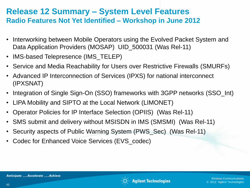
Release 12 Summary – System Level Features Radio Features Not Yet Identified – Workshop in June 2012
• Interworking between Mobile Operators using the Evolved Packet System and
Data Application Providers (MOSAP) UID_500031 (Was Rel-11)
• IMS-based Telepresence (IMS_TELEP)
• Service and Media Reachability for Users over Restrictive Firewalls (SMURFs)
• Advanced IP Interconnection of Services (IPXS) for national interconnect
(IPXSNAT)
• Integration of Single Sign-On (SSO) frameworks with 3GPP networks (SSO_Int)
• LIPA Mobility and SIPTO at the Local Network (LIMONET)
• Operator Policies for IP Interface Selection (OPIIS) (Was Rel-11)
• SMS submit and delivery without MSISDN in IMS (SMSMI) (Was Rel-11)
• Security aspects of Public Warning System (PWS_Sec) (Was Rel-11)
• Codec for Enhanced Voice Services (EVS_codec)
© 2012 Agilent Technologies
Wireless Communications
Questions?
44
Greater insight. Greater confidence. Accelerate next-generation wireless.