Embed Size (px)
Citation preview

Fundamentals of Surveying MSS 220
Prof. Gamal El-FikyMaritime Studies Department, Faculty of Marine Science
King Abdulaziz [email protected]
Room 221

What is Surveying?Surveying is defined as the science of collecting the
necessary field measurements to determine the 2-d and or 3-d positions on, above or under the earth’s surface.
In other words, it can be said that the surveying is a branch of science that works in determining the size and the shape of the earth.
To obtain such information, some field measurements should be acquired from the field using specialized instrumentation. Slope and horizontal distances, vertical and horizontal angles, height differences, directions and bearings are the different types of observations that are collected in surveying.

Classification of Surveying(i) According to the earth’s surface:a-
Plane surveying:Surveying area is relatively small (< 50 km2). All computations in any surveying process, in this type of surveying, are based on the plane as a computational surface.
b-Geodetic surveying:This type takes place in case of large areas (>50 km2)and long distances (>15 km).
Both effects of
refraction and earth curvature should be taken into account. The computational surface of the earth is either sphere (50 km2
<area>300 km2), or ellipsoid
(>300 km2).

(ii) According to its uses
1-
Land Surveying•
It is oriented towards the determination of the land boundaries. Also the preparation of maps showing the shapes and areas of land are included.
2-
Cadastral Surveying•
It works in surveying all types of features and/or utilities such as buildings, roads, green areas, waterlines, trees, water routes, etc. It is used to produce the cadastral maps of relatively large scale.
3-
Route surveying•
It is used to survey and prepare the maps required to design the route projects such as roads, canals, drains and railways.
(ii) According to its uses (Cont’d)
4-
Topographic surveying•
Where, full details to vertically control any project are obtained using the topographic surveying. Spot and grid leveling are performed using the topographic surveying to generate the topographic and the contour maps.
5-
Hydrographic surveying•
In which, all projects in and off the shore line are controlled. In addition, the preparation of the surveying maps needed for these kinds of projects are produced.

(iii) According to used instrumentation
•
1-
Chain surveyingIn which, mainly the linear measurements are used.
•
2-
Compass SurveyingIn which, mainly angles are measured using compass.
•
3-
Theodolite
SurveyingIn which, mainly angles are measured using compass.
•
4-
Total station SurveyingIn which, the total station is used to carry out the surveying.
•
5-
Photogrammetric SurveyA survey in which aerial photographs are used to determine the topography or the configuration of a tract.
•
f-
Satellite surveyingArtificial satellites are used to carry out the surveying works.

Unit of Measurements•
Angular Measure:
(i)-The degree system (sexagesimal
units) of angular
measurement are the degree, minute, and second. A plane angle extending completely around a point equals 360 degrees; one degree (°) = 60 minutes ('), and one minute = 60 seconds ("), so 1°
= 60' = 3600".
(ii) In Europe, the centesimal unit, the gon, is the angular unit; 400 gons
(g) equal 360°; 1 gon
(g) = 100 centesimal
minutes (c) = 0.9°; 1 centesimal minutes (c) = 100 centesimal seconds (cc) = 0°
00'
32.4“. Gons
usually are
expressed in decimals.Example: 100(g) 42(c) 88(cc)
is expressed as 100.4288 gons.

(iii) Radius System:•
An angle in radians is given by the ratio of the arc length, s, to the radius, r, θ
= s/r
•
Since a circle has circumference s = 2πr, the turning of a 360°
circle gives θ
= 360°
= 2π
×r/r
= 2π
radians, or π
radians = 180°.
•
Conversion from angles in degrees to radians must be done using decimal degrees.
•
Example: 57.0318°
is given in radians by57.0318 * (π
/ 180) = 0.9954 radians.

Unit of Linear Measures•
The international unit of linear measure is the meter. The meter
is subdivided into the following units:
1 decimeter (dm) = 0.1 meter (m) 1 centimeter (cm) = 0.01 meter (m) 1 millimeter (mm) = 0.001 meter (m) 1 micrometer (µm) = 10-6
meter (m)1 nanometer (dm) = 10-9
meter (m)
The relationship between meter and others linear units are:
1 inch = 2.54 cm = 1/39.36996 m1 foot = 12 inch = 3 yard = 1/0.3048 m1 nautical mile = 1852 m

Coordinate systems in Surveying
•
The coordinate system, in general, is a reference frame in which any point can be defined either in two or three dimensions. The coordinates of any point are necessary to be known in order to:
•
Define the horizontal and/or the vertical position.
•
Deal with different points on the earth’s surface.
•
Obtain any geometric relation between different points.
•
Plot easily and accurately any point on the map plane, using the manual and digital tools.

3-D Coordinate system (Φ, λ, h):
(i) Geodetic Curvilinear Coordinates System
Z
X
Y
GeodeticGreenwich
Meridian
Geodetic meridian of (a)
Terrain
a'
ha
Xa
Ya
Za
aλ
aφ
Geodetic Equator
North direction
a
Za

Geodetic curvilinear coordinates (Cont’d)
•
Geodetic curvilinear coordinates •
Geodetic latitude φ : is the angle measured form the equator to the point on the meridian plane of that point. φ varies from zero to 90 north or south.
•
Geodetic longitude λ : is the angle measured from Greenwich meridian to the point on the geodetic equator anti-clockwise direction. λ varies from 0 to 360 east or form 0º
to 180º
east and form 0º
to 180º
west.
•
Geodetic height h : Is the distance between the point and the sphere measured on the ellipsoid normal direction.
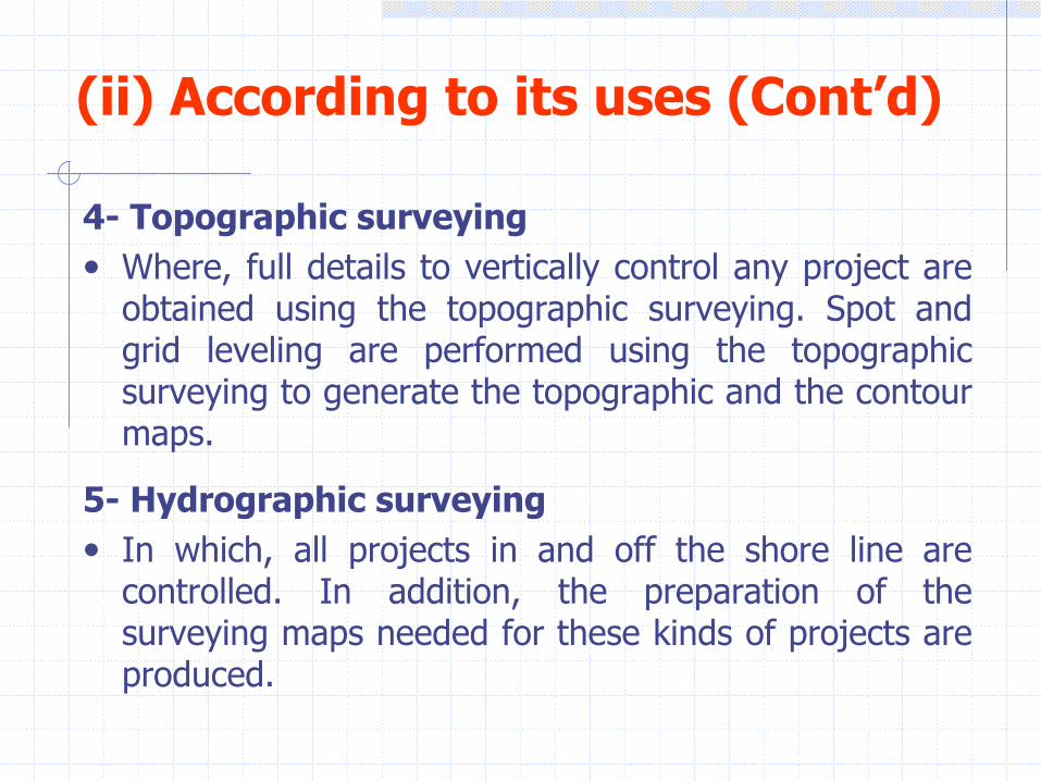
(ii) Geodetic Cartesian Coordinates : (X,Y,Z)
Where any point may be defined within the geodetic system by three Cartesian coordinates
•
X: The ordinates measured on the X axis direction
•
Y: The ordinates measured on the Y axis direction •
Z: The ordinates measured on the Z axis direction
•
Note that any of the above two sets of coordinates can be mathematically transformed to the other set and vice versa.

2-
Plane coordinates system (E, N):
This system consists of two axes; the north axis (N) and the east axis (E).
Any point can be defined by two coordinates in this system. Calculations, in such a system, are called as two dimensional (2-D) computations.
The coordinates of any point are nothing else, but the offsets to the two system axes.
E1
Easting (E)
Northing (N)
a
N1

Types of north direction
•
The
north direction at a point is the tangent to the meridian passes through the point. In this case, the north direction lines at different points are not parallel and there is a convergence of all north directions towards to the North Pole.
•
In small area, as the case of plane surveying, such a convergence does not exist and it is assumed that all north line directions are parallel. The following are the types of the north direction:
•
True north direction:•
It is the line tangent to the astronomic meridian at any point. It is measured by astronomic observations.

Types of north direction (Cont’d)
•
Magnetic north direction:•
It is the extension of the direction of the compass needle at a certain point when it is located free on the point. It is not constant and varies from point to point according to the internal metallic content of the earth at such a point.
•
Geographic north direction:•
It is the tangent of the geodetic meridian at any point. It is some time called as the theoretical north direction at any point.
•
Local north direction:•
In some small projects, it is possible to choose an arbitrary direction. This direction can be temporally considered as the north direction of such a project.

Bearing of a Line in Surveying
•
The bearing of any line in surveying is an angle measured from a reference direction, (the north direction) to the line. The bearing of any line may be described by: (i) the whole circle bearing or (ii) the reduced bearing.
(i)-
The Whole Circle Bearing of a Line (WCB) (α)
: •
It is the angle measured form the north direction to that line clockwise direction. It ranges from 0˚
to
360˚. The bearing of any line is considered as the definition of the line orientation.
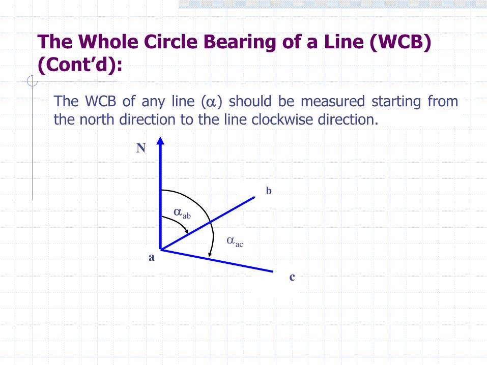
The Whole Circle Bearing of a Line (WCB) (Cont’d):
αab
αac
b
ca
N
The WCB of any line (α) should be measured starting from the north direction to the line clockwise direction.

(ii) The Reduced Bearing (RB) (α‘)•
The reduced bearing of any line is defined as the angle measured between the north-south line to that line under the condition that its value is ranging between 0-90 degrees. In this case the RB should be represented as a value assigned a certain symbol to show the quarter in which the line is located.
320o
N
G
= 320o
EW
S
H
N 40 Wo
=
235o
N
E
F = 235o
EW
S= S 55 W
o
60o
N
A
B
= 60o
EW
S = N 60 Eo
120o
N
C
D= 120o
EW
S= S 60 Eo
Fourth quarter Third quarter Second quarter First quarter

Transformation between WCB (α) and RB (α')
WCB is preferred to be used in all surveying calculation, where the algebraic sign is considered according to the location of the side. In this case, we need usually to transform the RB (α') to WCB (α) , especially in case of using a computed bearing.
Values of WCB (α) Values of RB (α') No. Circle Quarter0°
~ 90°
N (α°) E First quarter
90°
~ 180°
S (180°
-
α°) E Second quarter180°
~ 270°
S (α°
-
180°) W Third quarter
270°
~ 360°
N (360°
-
α°) W Fourth quarter
235o
N
E
F = 235o
EW
S
320o
N
G
= 320o
EW
S
H
= S 55 WoN 40 W
o=
60o
N
A
B
= 60o
EW
S
120o
N
C
D= 120o
EW
S = N 60 Eo
= S 60 Eo

Forward and Backward Bearing of a Line
•
Any line is named as AB, then, automatically, a point A indicates the occupied station, while the other point b indicates the target station. In this case, the WCB (αAB
) of that line is called as the forward bearing of AB, where the bearing is named using the same sequence as the line name.
•
If we have, then the bearing in this case is named as the backward bearing of the line AB (αBA
).•
We can describe the relationship between both forward and backward bearing as
•
αAB
= α
BA
±
180o
•
where the +ve
sign takes place
when α
AB
< 180o, and
•
The –ve
sign takes place if α
AB
> 180o.
•
Note that the bearing shouldnot exceed 360˚
N
A
B
N
AB
180o
AB
AB

Relation Between Angles and Bearings
•
In the shown figure, it is clear that the angle enclosed by the two lines ab
and ac
at point a
equals the difference between the bearings of the two lines ac and ab.
•
According to the sequence of writingthe angle, it indicates which horizontalangle internal or external is required,as an example if we write , here wemean the internal angle w1
•
In this case, we can write
N
bâc=W1acα
abα
a
c
ˆ ac abbac α α= −
b

Example•
Given : , αab
= 45º00'00" αad
= 300º00'00", and bâc= 88º30‘20" Required: , αac
, câd
and dâb
•
Solution:
•
bâc
= αac
-
αab
•
Then 88º30‘20"
= αac
-
45º00'00“
•
αac
= 133º30‘20“
•
câd
= αad
-
αac = 300º00'00" -
133º30‘20“
= 166º29‘40“
•
dâb
= αab
-
αad = 45º00'00" -
300º00‘00“
= -255º00‘00“
•
We have to add 360o
•
Then,
•
dâb
= 360º
-
255º00‘00“
= 105º00‘00“
N
a
b
ab
c
88 30 20
d
ad
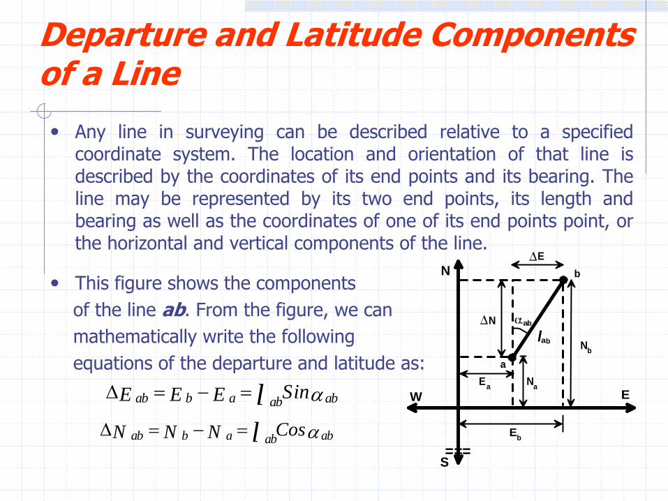
Departure and Latitude Components of a Line•
Any line in surveying can be described relative to a specified coordinate system. The location and orientation of that line is described by the coordinates of its end points and its bearing. The line may be represented by its two end points, its length and bearing as well as the coordinates of one of its end points point, or the horizontal and vertical components of the line.
•
This figure shows the componentsof the line ab. From the figure, we canmathematically write the followingequations of the departure and latitude as:
ab b a ababSinE E E l αΔ = − =
ab b a ababCosN N N l αΔ = − =
a
N
EW
b
Ea Na
Nb
N
Eb
E
l
===S
ab
ab

Components of a Line (Cont’d)
•
The coordinates of point a are (Ea,Na
)
•
The coordinates of point b are (Eb,Nb
)
•
The length of the line ab is lab
.
•
The bearing of the line αab
is .
•
The horizontal component of the line ab (departure) is ΔEab
•
The vertical component of the line ab (latitude) is ΔNab
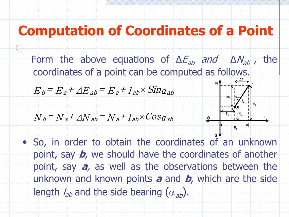
Computation of Coordinates of a Point
Form the above equations of ΔEab
and ΔNab
, the coordinates of a point can be computed as follows.
•
So, in order to obtain the coordinates of an unknown point, say b, we should have the coordinates of another point, say a, as well as the observations between the unknown and known points a and b, which are the side length lab
and the side bearing (αab
).
×b a ab a ab ab= + = + SinE E ΔE E l α
×b a ab a ab ab= + = + CosN N ΔN N l αa
N
EW
b
Ea Na
Nb
N
Eb
E
l
===S
ab
ab

Example•
Calculate the coordinates of points b and c if the coordinates of point a are given as (265.38m, 377.39m ), the bearing of the line is αab
= 45°13‘33“
and the horizontal angle bâc =230°10‘29"
, the lengths of ab are 174.57 m and ac 201.34m, respectively.
•
Solution:•
To compute the coordinates of point b, we use the following equations:
•
On the other hand, to obtain the coordinates of the point c, first, we have to calculate the bearing of the line ac as: then,
b a ab a ab ab= + = + ×SinE E ΔE E l α
=265.38+174.57×Sin45°13'33"=389.305mb
a lab
bâc
cN
αablac
b a ab a ab ab= + = + ×CosN N ΔN N l α
=377.39+174.57cos45°13'33"=500.342m

Example (Cont’d)ˆ ac abbac= -α α
ˆac ab=bac+ =230°10'29"+45°13'33"=275°24'02"α α
And then we can compute the coordinates of point c as:
c a ac a ac ac
o
c a ac a ac ac
o
= + = + ×Sin =E E ΔE E l α
265.39 + 201.34 ×Sin 24'02" = 64.943m275
= + = + ×Cos =N N ΔN N l α
265.39 + 201.34×Cos 24'02" = 284.339m275

Computations of the Length and Bearing of a Line from CoordinatesHere, we have the coordinates of the points a and b and it is required to compute the length of the line ab and both forward and backward bearing of that line.ΔEab
= Xb
- Xa
, ΔNab
= Yb
– Ya
lab
=
αab
=
arctan
Where, ΔEab
and ΔNab
are the departure
and latitude of the line ab, respectively.
( ) ( )+2 2ab abΔNΔE
a
N
EW
b
Ea Na
Nb
N
Eb
E
l
===S
ab
abab
ab
ΔEΔN

RemarksIt should be mentioned here that, the resulted value of the bearing is ranging between 0º and 90º. This means that the resulted bearing is a reduced bearing and then should be assigned symbols to determine the quarter in which the line is located. To do so, we have to determine the algebraic sign of both departure and latitude, which may be one of the following four cases:If the sign of ΔE is positive and ΔN is positive then the line is located in the first quarter and,If the sign of ΔE is negative and ΔN is positive then the line is located in the second quarter and,If the sign of ΔE is negative and ΔN is negative then the line is located in the third quarter and,If the sign of ΔE is positive and ΔN is negative then the line is located in the fourth quarter.Once, the case of both departure and latitude is chosen the WCB can be computed from the reduced bearing, as discussed before.On the other hand, the backward bearing of the line ab, we can simply apply the above equations of relating both backward and forward bearings.

Example•
If the coordinates (in meter) of point P are (500E,250N) and the coordinates of point Q
are (250W,500S), estimate the length of the line PQ and its bearing.
•
Solution:•
ΔEPQ
= -250 -
(500) = -750m •
ΔNPQ
= -500 -
(250) = -750 m
•
Tan α
=•
Since the sign of ΔE is negative and ΔN is negative then the line is located in the third
quarter
and
α= 225o
,
•
lPQ
= [(750)2
+ (750)2
]1/2
= 1060.66
m
P
N
EW
Q
X = 500P
Y = 500Q
X = 250Q
S
X
Y
L
Y = 250P
ΔE -750= =1
ΔN -750


![i cro eparate Screen Y 100 Y) 30 O. 1kWi cro eparate Screen Y 100 Y) 30 O. 1kW 3ØX200VXO.1 kW MSS- 300 MSS- 600 MSS- 900 MSS -1200 MSS- 1500 MSS- 1800 [kg] 200 260 325 455 520 585](https://img.pdfslide.us/doc/110x75/608f28a1057c035c36673166/i-cro-eparate-screen-y-100-y-30-o-1kw-i-cro-eparate-screen-y-100-y-30-o-1kw.jpg)