Embed Size (px)
Citation preview

Fundamentals of Computer GraphicsPart 4
prof.ing.Václav Skala, CSc.University of West Bohemia
Plzeň, Czech Republic
©2002Prepared with Angel,E.: Interactive Computer
Graphics – A Top Down Approach with OpenGL, Addison Wesley, 2001

Fundamentals of Computer Graphics 2
Geometric Transformations
• Concentration on 3D graphics
• Affine & Euclidean vector spaces
• Homogeneous coordinates
• Formalities of vector spaces & matrix algebra – see App.B&C
Goals:
• method for dealing with geometric objects – independent of a coordinate system
• coordinate free approach & homogeneous coordinates

Fundamentals of Computer Graphics 3
Scalars, Points & Vectors
• Most geometric objects can be defined by a limited set of primitives, like scalars, points, vectors
• Different perspectives:
– mathematical
– programming
– geometric
BUT ALL are important for understanding
• vector = directed (oriented) line segment
• vectors have no fixed position!

Fundamentals of Computer Graphics 4
Geometric View
• vectors have no fixed position
• had-to-tail rule – useful to express functionalityC = A + B
• points & vectors – distinct geometric types!
• a given vector can be defined as from a fixed reference point (origin) to the given point p (dangerous vector repr.)

Fundamentals of Computer Graphics 5
Vector & Affine Spaces Vector (linear) space
• vector & scalars – addition &multiplication operations used to form a scalar field (scalars – real, complex numbers, rational functions – typical Ax=0, n-tuples etc.)
Affine space – extension of vector space – the point is an object
• vector-point addition, point-point subtraction, geometric operations with points etc.
Euclidean space – enables to measure distance, size
Details see in the App.B & C

Fundamentals of Computer Graphics 6
Representation • Mathematicians – scalars, points, vectors etc. – they are
distinguished by symbols and fonts (bold, capital, italic etc.)
• Computer scientists – Abstract Data Types – ADT – set of operations on data; operations independent from the actual physical realization/implementationData abstraction – fundamental to Computer Sciencebut causes difficulties in a code understanding
What is the meaning of a sequence in C++ :
q = p + a * v;

Fundamentals of Computer Graphics 7
Representation What is the meaning of a sequence in C++ :
q = p + a * v;
can be determined if the definition is known:
vector u, v;
point p, q;
scalar a, b;
and their actual meaning must be vector type as a vector !
OpenGL is not object oriented so far

Fundamentals of Computer Graphics 8
Geometric ADT & Lines Symbols:
, , - scalars
P, Q, R – points
u, v, w – vectors
Typical geometrical operations:
| v| = | | | v |
v = P – Q => P = v + Q
( P – Q )+ ( Q – R ) = P – R
P() = P0 + d (a line in an affine space – param.form)

Fundamentals of Computer Graphics 9
Affine Sums new point P can be defined as
P = Q + v
Point R
v = R – Q
and
P = Q + (R –Q)= R + (1- )Q
P = 1 R+ 2 Q
where
1 + 2 = 1

Fundamentals of Computer Graphics 10
Convexity A convex object is one for which any
point lying on the line segment connecting any two points in the object is also in the object
P = 1 R+ 2 Q & 1+ 2 = 1
More general form
P = 1P1+2P2 +... +nPn
where
1+2 +... +n= 1&
i 0 , i = 1, 2, ....,n

Fundamentals of Computer Graphics 11
Planes Let P, Q, R are points defining
a plane in an affine space
S() = P + (1- )Q , 0 1
T() = S + (1 - ) R , 0 1
using a substitution
T(,) = [ P + (1- )Q ] + ( 1 - ) R , 0 1 & 0 1
T(,) = P + (1 - )( Q – P ) + (1 - ) (R – P)
Plane given by a point P0 and vectors u, v
T(,) = P0 + u + v & 0 , 1

Fundamentals of Computer Graphics 12
Planes A triangle is defined as (a plane has no limits for , )
T(,) = P0 + u + v & 0 , 1
If a point P lies in the plane then
P - P0 = u + v
Let
w = u x v (cross product)
The vector w is orthogonal to the plane
and the equation
wT (P – P0) = 0 (criterion for a test: point in the plane)
vector w is called a normal vector and symbol n is often used

Fundamentals of Computer Graphics 13
Three Dimensional Primitives• Full range of graphics primitives cannot be supported by
graphics systems – some are approximated
• most graphics systems optimized for procession points and polygons, polygons in E3 are not planar – tessellation is required or made by the system itself
• Constructive Solid Geometry (CSG) – objects build using set operations like union, intersection, difference etc.

Fundamentals of Computer Graphics 14
Coordinate Systems and Frames A vector w is defined as
w = 1v1 + 2v2 + 3v3
1, 2, 3 are components of w
with respect to the basis vectors
v1 ,v2 ,v3 (! toto jsou bázové vektory)
• vectors v forms coordinate system in vector space
• points representation needs to “fix” the origin – reference point and basis vectors are required - frame

Fundamentals of Computer Graphics 15
Coordinate Systems and Frames
Within a given frame every vector can be written uniquely as
w = 1v1 + 2v2 + 3v3
just as in a vector space.
v1 = [ 1, 0 , 0]T
v2 = [ 0, 1 , 0]T
v3 = [ 0, 0 , 1]T
Every point can be written uniquely as
w = P0 + 1v1 + 2v2 + 3v3
3
2
1
a
3
2
1
321
v
v
v
w

Fundamentals of Computer Graphics 16
Changes of Coordinate Systems Suppose that
{v1 , v2 , v3 } & {u1 , u2 , u3 }
are two basis vectors.
Therefore 9 scalar components
exist { ij} such as
u = M v
a vector w with respect to v = [v1 , v2 , v3 ]T
a = [1 , 2 , 3 ]T
w = aT va vector w with respect to
v = [u1 , u2 , u3 ]T
b = [ß1 , ß2 , ß3 ]T
w = bT uw = bT u = bT M v = aT v
bT M = aT a = MT b
3
2
1
333231
232221
131211
3
2
1
v
v
v
u
u
u

Fundamentals of Computer Graphics 17
Changes of Coordinate Systems The origin unchanged
- rotation, scaling representation
u = M v
Simple translation or a change of a frame cannot be represented in this way
Study change of representation – chapter 4.3.2 on your own

Fundamentals of Computer Graphics 18
Homogeneous coordinates A point P located at (x,y,z) is represented using a 3D frame
by
P0, v1, v2, v3 as p = [ x , y , z ]T
therefore
P = P0 + x v1+ y v2 + z v3
and point P can be determined as P = 1v1 + 2v2 + 3v3 + P0
P = [1 , 2 , 3 , 1] [v1 , v2 , v3 , P0 ]T
Every point can be written uniquely as
w = P0 + 1v1 + 2v2 + 3v3

Fundamentals of Computer Graphics 19
Homogeneous Coordinates
Suppose that
{v1 , v2 , v3 , P0 }&{u1 , u2 , u3 , Q0 }
are two basis vectors.
Therefore 16 scalar components
exist { ij} such as
u = M v
a vector w with respect to v = [v1 , v2 , v3 , P0 ]T
= [1 , 2 , 3 , 1]T
w = aT va vector w with respect to
v = [u1 , u2 , u3 , Q0]T
= [ß1 , ß2 , ß3 , 1]T
w = bT uw = bT u = bT M v = aT vbT M = aT a = MT b
Study Change in Frames and Frames&ADT Chapters 4.3.4.-5. on your own
0
3
2
1
434241
333231
232221
131211
0
3
2
1
1
0
0
0
P
v
v
v
Q
u
u
u

Fundamentals of Computer Graphics 20
Frames in OpenGL Two frames – camera & world frames
Consider the camera frame fixed
• model-view matrix converts the homogeneous coordinate representations of points and vectors to their representations in the camera frame
• the model-view matrix is part of the state of the system – there is always a camera frame and a present-world frame(how to define new frames – next chapters)
• three basis vectors correspond to up, y, z -directions,

Fundamentals of Computer Graphics 21
Frames in OpenGL Default settings:
• Camera & Worldframes the same
• Objects must moved away from camera or
• Camera must be moved away from objects
If camera frame fixed & model-view positioning world frame to camera frame then model-view matrix A is defined as ( d- distance):
1000
100
0010
0001
dA

Fundamentals of Computer Graphics 22
Frames in OpenGL Moves points (x,y,z) in the world frame
to (x,y,z,-d) in the camera frame
This concept is better than the repositioning objects position by changing their vertices
Setting the Model-View matrix by sending an array of 16 elements to glLoadMatrix
User working in the world coordinates positions the objects as before
Fundamentals of Computer Graphics 23
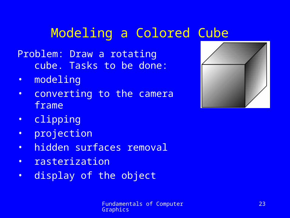
Modeling a Colored Cube Problem: Draw a rotating cube. Tasks
to be done:
• modeling
• converting to the camera frame
• clipping
• projection
• hidden surfaces removal
• rasterization
• display of the object
Fundamentals of Computer Graphics 24
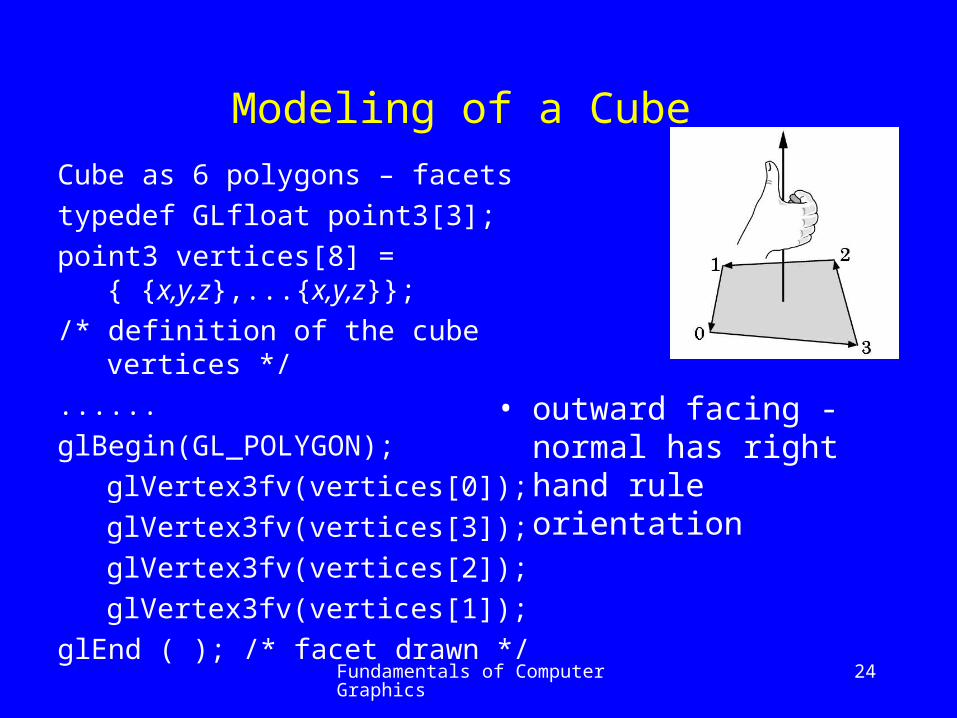
Modeling of a Cube Cube as 6 polygons – facets
typedef GLfloat point3[3];
point3 vertices[8] = { {x,y,z},...{x,y,z}};
/* definition of the cube vertices */
......
glBegin(GL_POLYGON);
glVertex3fv(vertices[0]);
glVertex3fv(vertices[3]);
glVertex3fv(vertices[2]);
glVertex3fv(vertices[1]);
glEnd ( ); /* facet drawn */
• outward facing - normal has right hand rule orientation
Fundamentals of Computer Graphics 25
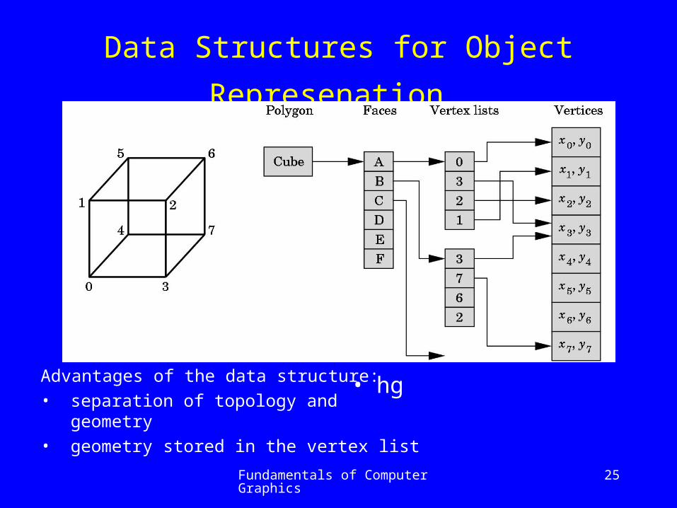
Data Structures for Object Represenation
Advantages of the data structure:
• separation of topology and geometry
• geometry stored in the vertex list
• hg

Fundamentals of Computer Graphics 26
typedef GLfloat point3[3];
point3 vertices [8] ={{x,y,z}, ... ,{x,y,z}}; /* vertices x,y,z coordinates def. */
GLfloat Colors[8][3] = {{r,g,b}, .... , {r,g,b}}; /* color defs. */
void quad(int a, int b, int c, int d)
{ glBegin(GL_QUADS);
glColor3fv(colors[a]);glVertex3fv(vertices[a]);
glColor3fv(colors[b]);glVertex3fv(vertices[b]);
glColor3fv(colors[c]);glVertex3fv(vertices[c]);
glColor3fv(colors[d]);glVertex3fv(vertices[d]);
glEnd ( );
}
Data Structures for Object Represenation

Fundamentals of Computer Graphics 27
Data Structures for Object Representation
void colorcube( );/*draws a cube*/
{ quad(0,3,2,1); quad(2,3,7,6);
quad(0,4,7,3); quad(1,2,6,5);
quad(4,5,6,7); quad(0,1,5,4); }
color is specified - graphics system must decide how to fill
bilinear interpolation
C01() = (1- )C0+ C1
C23() = (1- )C2+ C3
for the given value C01() = C4 , C23() = C5
C45() = (1- )C0+ C5
scan-line interpolation
OpenGL provides this for others values that are assigned on the vertex-to-vertex basis
Fundamentals of Computer Graphics 28
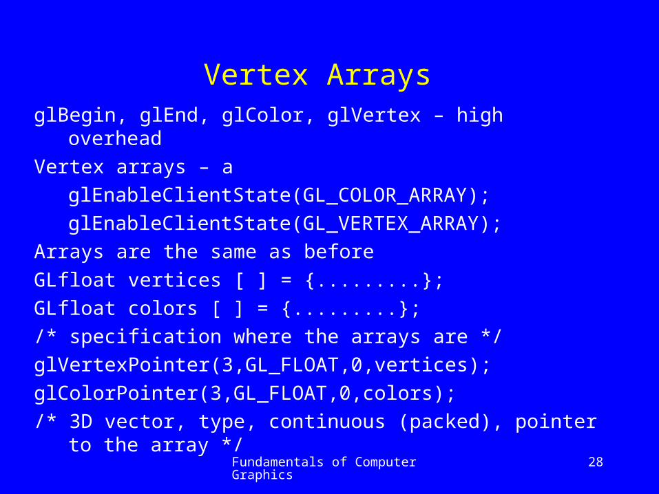
Vertex Arrays glBegin, glEnd, glColor, glVertex – high overhead
Vertex arrays – a
glEnableClientState(GL_COLOR_ARRAY);
glEnableClientState(GL_VERTEX_ARRAY);
Arrays are the same as before
GLfloat vertices [ ] = {.........};
GLfloat colors [ ] = {.........};
/* specification where the arrays are */
glVertexPointer(3,GL_FLOAT,0,vertices);
glColorPointer(3,GL_FLOAT,0,colors);
/* 3D vector, type, continuous (packed), pointer to the array */

Fundamentals of Computer Graphics 29
Vertex Arrays The facets must be specifiedGLubyte cubeIndices [24] =
{0,3,2,1,2,3,7,6,0,4,7,3,1,2,6,5,4,5,6,7,0,1,5,4};/* facets are formed by 4 vertices */Options how to draw:
glDrawElements(type,n,format,pointer);-------------- SOLUTION ------------for ( i=0; i<6; i++) /* n number of elements */
glDrawElements(GL_POLYGON,4,GL_UNSIGNED_BYTE, &cubeIndicis[4*i]);
or with a single callglDrawElements(GL_QUADS,24,
GL_UNSIGNED_BYTE, &cubeIndices);

Fundamentals of Computer Graphics 30
Affine Transformations Chapter 4.5 – study on your own

Fundamentals of Computer Graphics 31
Rotation, translation and Scaling Translation
P’ = P + d
Rotation
x = cos y = sin x’ = cos (+) y’ = sin (+)
y
x
y
x
cossin
sincos
'
'

Fundamentals of Computer Graphics 32
Rotation about a fixed point
For rotation – implicit point
- origin
- 2D – simple
- 3D –complicated
Transformation
- rigid-body
- non-rigid-body
reflections

Fundamentals of Computer Graphics 33
Transformation in Homogeneous Coordinates
Translation
Scaling
Inversion operations:
T-1 = T ( -x , -y , -z )
S-1 = S ( 1/x , 1/ y , 1/ z )
1000
100
010
001
z
y
x
T
1000
000
000
000
z
y
x
S

Fundamentals of Computer Graphics 34
Transformation in Homogeneous Coordinates
Rotation in x-y plane
Rotation in y-z plane
Rotation in z-x plane
R-1 () = R ( - ) = RT ()
1000
0100
00cossin
00sincos
xyR
1000
0cossin0
0sincos0
0001
yzR
1000
0cos0sin
0010
0sin0cos
zxR

Fundamentals of Computer Graphics 35
Transformations Concatenation
Concatenation –
well known strategy
q = C B A p
interpretation
q = C (B (A p) )
Transformation
q = M p

Fundamentals of Computer Graphics 36
Rotation About a Fixed PointRotation about the fixed
point
M = T(pf ) Rz( ) T(- pf )

Fundamentals of Computer Graphics 37
Rotation About a Fixed Point
Rotation about the fixed point
M = T(pf ) Rz( ) T(- pf )

Fundamentals of Computer Graphics 38
Rotations in E3
Cube can be rotated about all x, y, z axis
In our case the transformation matrix is defined
M = Rzx Ryz Rxy = Ry Rx Rz
Rxy Ryz
Rzx

Fundamentals of Computer Graphics 39
Rotations in E3Transformation is defined by the
instance transformation M
M = T R S(order is substantial!)
Each occurrence of an object in the scene is an instance of the object’s prototype
To obtain proper size, location, orientation – instance transformation to the prototype is to be applied

Fundamentals of Computer Graphics 40
Rotations About an Arbitrary Axis Given:
• points p1 , p2 and rotation angle
• objects to be rotated
Define vectors u = p1 - p2
and v = u / |u| - normalized
v = [ x , y , z ]T
x2 + y
2 + z2 = 1 – directional cosines
cos( x ) = x , cos( y ) = y , cos( z ) = z
cos2( x ) + cos2( y ) + cos2 ( z ) = 1
only two directions angles are independent !!

Fundamentals of Computer Graphics 41
Rotations About an Arbitrary Axis
Transformation
R = Rx(-x) Ry(-y) Rz() Ry(y) Rx(x)

Fundamentals of Computer Graphics 42
Rotations About an Arbitrary Axis • Object is moved to the origin
• Rotation about x axis
22
1000
0//0
0//0
0001
zy
zy
yzxx
d
dd
ddR

Fundamentals of Computer Graphics 43
Rotations About an Arbitrary Axis • Object is moved to the origin
• Rotation about y axisnote the “-” position
Complete transformation
M = T(p0) Rx(-x) Ry(-y) Rz() Ry(y) Rx(x) T(- p0)
22
1000
0/0/
0010
0/0/
zy
zx
xz
xx
d
dd
dd
R

Fundamentals of Computer Graphics 44
OpenGL Transformation Matrices
Three matrices as a part of the state in OpenGL
Only Model-View will be used
CMT – current transformation matrix – can be changed by OpenGL functions – 4 x 4 size
Supported operations: translation, scaling & rotation – last two with the fixed point in the origin
C I initialization C CT translation
C CS scaling C CR rotation

Fundamentals of Computer Graphics 45
OpenGL Transformation Matrices
Most systems allow to set directly or load or post-multiply the CMT with an arbitrary matrix M , scaling & rotation – last two with the fixed point in the origin
C M loading
C CM post-multiplication

Fundamentals of Computer Graphics 46
OpenGL Transformation Matrices
OpenGL model-view (GL_MODELVIEW) and projection (GL_PROJECTION) matrices (actually their product) are applied to ALL primitives – we should consider them as one CMT matrix – can be manipulated individually using glMatrixMode function
glLoadMatrixf(pointer_to_matrix); /* vector of 16 position – column first order */

Fundamentals of Computer Graphics 47
OpenGL Transformation Matrices
glLoadIdentity ( ); /* loads identity matrix */
glRotatef(angle, vx, vy, vz); /* f – float used */
/* specifies general rotation angle in degrees, v – specifies the vector – fixed point P0 is the origin */
glTranslatef(dx, dy, dz); /* translation */
glScalef ( sx, sy, sz); /* scaling */

Fundamentals of Computer Graphics 48
Rotation about a Fixed Point
glMatrixMode(GL_MODELVIEW);
glLoadIdentity ( );
glTranslatef(4.0, 5.0, 6.0);
glRotatef(45.0, 1.0, 2.0, 3.0);
glTranslatef(-4.0, -5.0, -6.0);
/* rotates objects about the vector (1.0, 2.0, 3.0) with the angle 45° */
NOTE:
we need not to form the rotation matrices as shown recently – try to make it on your own

Fundamentals of Computer Graphics 49
Transformation Order
The sequence specified recently:
C I, initialization
C CT (4.0, 5.0, 6.0), translation
C CR (45.0, 1.0, 2.0, 3.0), rotation
C CT (-4.0, -5.0, -6.0), translation back
in each step the CTM matrix is post-multiplied forming new CTM matrix
C = T (4.0, 5.0, 6.0) R(45.0, 1.0, 2.0, 3.0) T (-4.0, -5.0, -6.0)
Each vertex specified after the model-view matrix has been specified will be multiplied
p’ = C p

Fundamentals of Computer Graphics 50
Spinning of the Cube
Three callback functions:
glutDisplayFunc(display); glutIdleFunc(spincube);
glutMouseFunc(mouse);
void display(void); /* visibility made by HW – GL_DEPTH.... */
{glClear(GL_COLOR_BUFFER_BIT | GL_DEPTH_BUFFER_BIT);
glLoadIdentity ( ); glRotatef(theta[0];1.0, 0.0, 0.0);
glRotatef(theta[1];0.0, 1.0, 0.0); glRotatef(theta[2];0.0, 0.0, 1.0);
colorcube ( );
glutSwapBuffers ( ); /* swaps the buffers – drawing to the display */
} /* theta vector – global variable */

Fundamentals of Computer Graphics 51
Spinning of the Cube
void spincube ( );
{ theta[axis] +=2.0; if (theta[axis] >360.0) theta[axis] -=360.0;
glutPostRedisplay ( ); }
void mouse (int btn, int state, int x, int y);{ if (btn==GLUT_LEFT_BUTTON && state == GLUT_DOWN) axis=0;
if (btn==GLUT_MIDDLE_BUTTON && state == GLUT_DOWN) axis=1;
if (btn==GLUT_RIGHT_BUTTON && state == GLUT_DOWN) axis=2; }
void mykey(char key, int mouse x, int mouse y);
{ if (key==‘q’ | | key==‘Q’ ) exit ( ); } /* simple termination */

Fundamentals of Computer Graphics 52
Loading, Pushing & Popping
glLoadMatrixf(myarray);
/* 4 x 4 matrix of floats -column first order from a vector */
glMultMatrixf(myarray);
/* multiplies the current matrix by user specified matrix */
Sequence example
GLfloat myarray [16];
for ( i=0; i<3; i++)
for ( j=0; j<3; j++)
myarray[4*j+i] = m[i][j];

Fundamentals of Computer Graphics 53
Loading, Pushing & Popping
Sometimes it is reasonable to return the transformations back after they have been applied to some objects.
Instead of re-computation the stack mechanism can be utilized
glPushMatrix ( );
/* local transformation specifications */
glTranslatef ( .....); ................
/* DRAW OBJECTS HERE */
................
/* recover recent state */
glPopMatrix ( );

Fundamentals of Computer Graphics 54
Interfaces to 3D Applications
Study the Chapters 4.10 - 12 on your own

Fundamentals of Computer Graphics 55
Conclusion Chapter 4
You have learnt in this chapter:
• how transformations are defined
• how can you use them
• how to construct quite complicated transformations
Mention, please, that you are now capable to write quite complicated program with graphics output and input
Next time we will learn how to represent different viewing principles, projections etc.