Embed Size (px)
Citation preview
Fundamentals of Cellular Fundamentals of Cellular NetworksNetworks
David TipperAssociate ProfessorAssociate Professor
Graduate Program in Telecommunicationsand Networking
University of PittsburghSlides 4Slides 4
TelcomTelcom 2720 2720
Telcom 2720 2
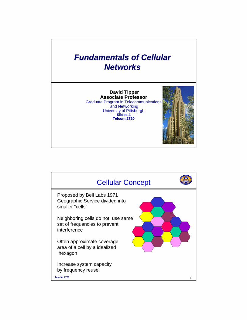
Cellular ConceptProposed by Bell Labs 1971 Geographic Service divided into smaller “cells”
Neighboring cells do not use same set of frequencies to prevent interference
Often approximate coveragearea of a cell by a idealizedhexagon
Increase system capacityby frequency reuse.
Telcom 2720 3
Cellular Networks
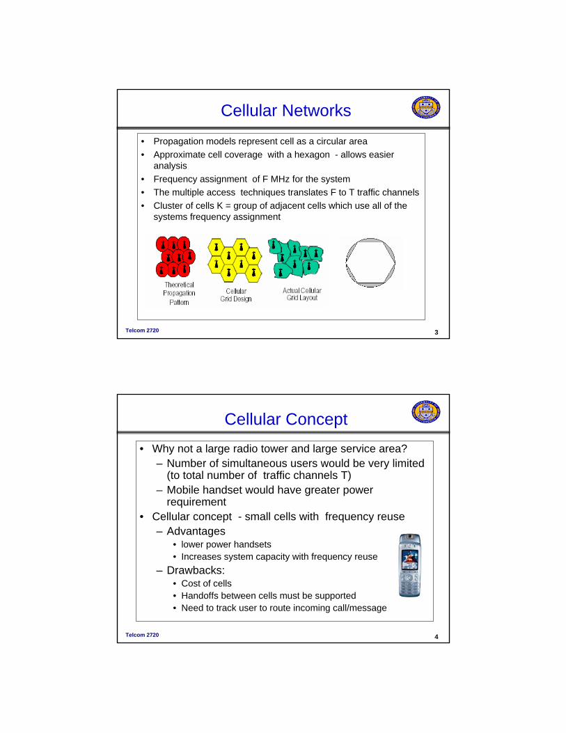
• Propagation models represent cell as a circular area• Approximate cell coverage with a hexagon - allows easier
analysis• Frequency assignment of F MHz for the system• The multiple access techniques translates F to T traffic channels• Cluster of cells K = group of adjacent cells which use all of the
systems frequency assignment
Telcom 2720 4
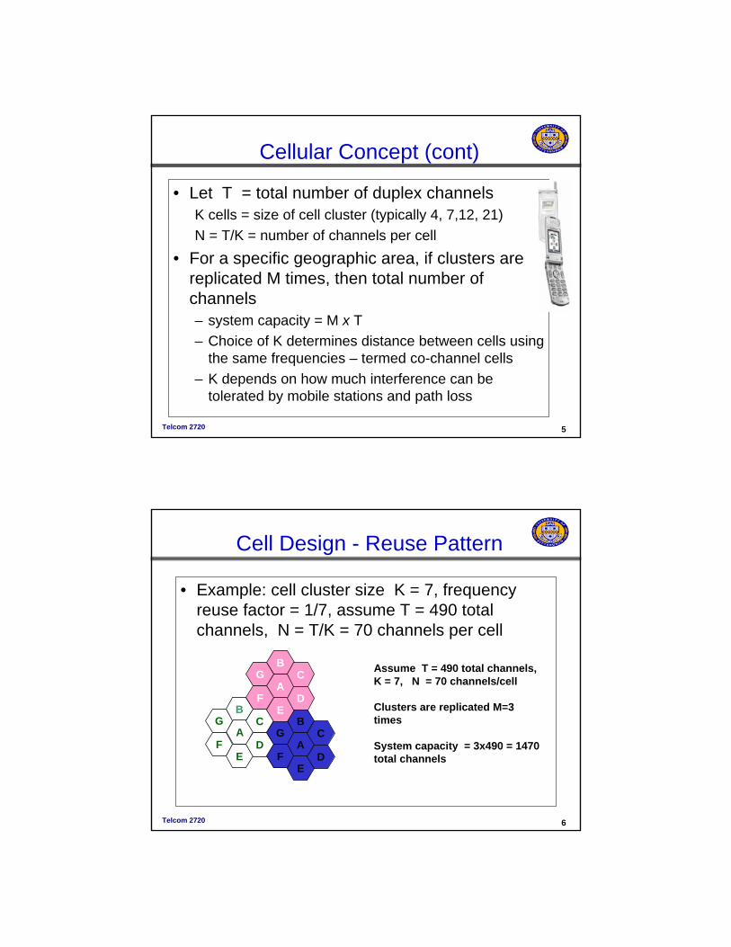
Cellular Concept• Why not a large radio tower and large service area?
– Number of simultaneous users would be very limited (to total number of traffic channels T)
– Mobile handset would have greater power requirement
• Cellular concept - small cells with frequency reuse– Advantages
• lower power handsets• Increases system capacity with frequency reuse
– Drawbacks:• Cost of cells• Handoffs between cells must be supported• Need to track user to route incoming call/message
Telcom 2720 5
Cellular Concept (cont)
• Let T = total number of duplex channelsK cells = size of cell cluster (typically 4, 7,12, 21)N = T/K = number of channels per cell
• For a specific geographic area, if clusters are replicated M times, then total number of channels – system capacity = M x T – Choice of K determines distance between cells using
the same frequencies – termed co-channel cells – K depends on how much interference can be
tolerated by mobile stations and path loss
Telcom 2720 6
Cell Design - Reuse Pattern
• Example: cell cluster size K = 7, frequency reuse factor = 1/7, assume T = 490 total channels, N = T/K = 70 channels per cell
B
A
E
C
D
G
F
B
A
E
C
D
G
F
B
A
E
C
D
G
F
Assume T = 490 total channels,K = 7, N = 70 channels/cell
Clusters are replicated M=3 times
System capacity = 3x490 = 1470 total channels
Telcom 2720 7
Cluster Size
132
43 1
42
12
34
1
31
42
6 75
1
1
11
1
1
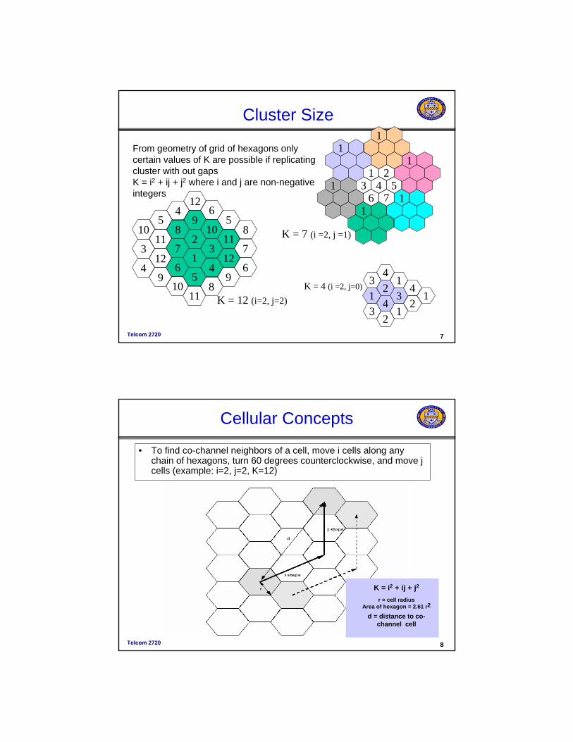
K = 4 (i =2, j=0)
K = 7 (i =2, j =1)2
98
6
71
3
1011
124
5
65
8
6
7
98
124
5
3
1011
124
910
11 K = 12 (i=2, j=2)
From geometry of grid of hexagons only certain values of K are possible if replicating cluster with out gapsK = i2 + ij + j2 where i and j are non-negative integers
Telcom 2720 8
Cellular Concepts
• To find co-channel neighbors of a cell, move i cells along any chain of hexagons, turn 60 degrees counterclockwise, and move j cells (example: i=2, j=2, K=12)
K = i2 + ij + j2
r = cell radiusArea of hexagon = 2.61 r2
d = distance to co-channel cell
Telcom 2720 9
Cellular Concepts
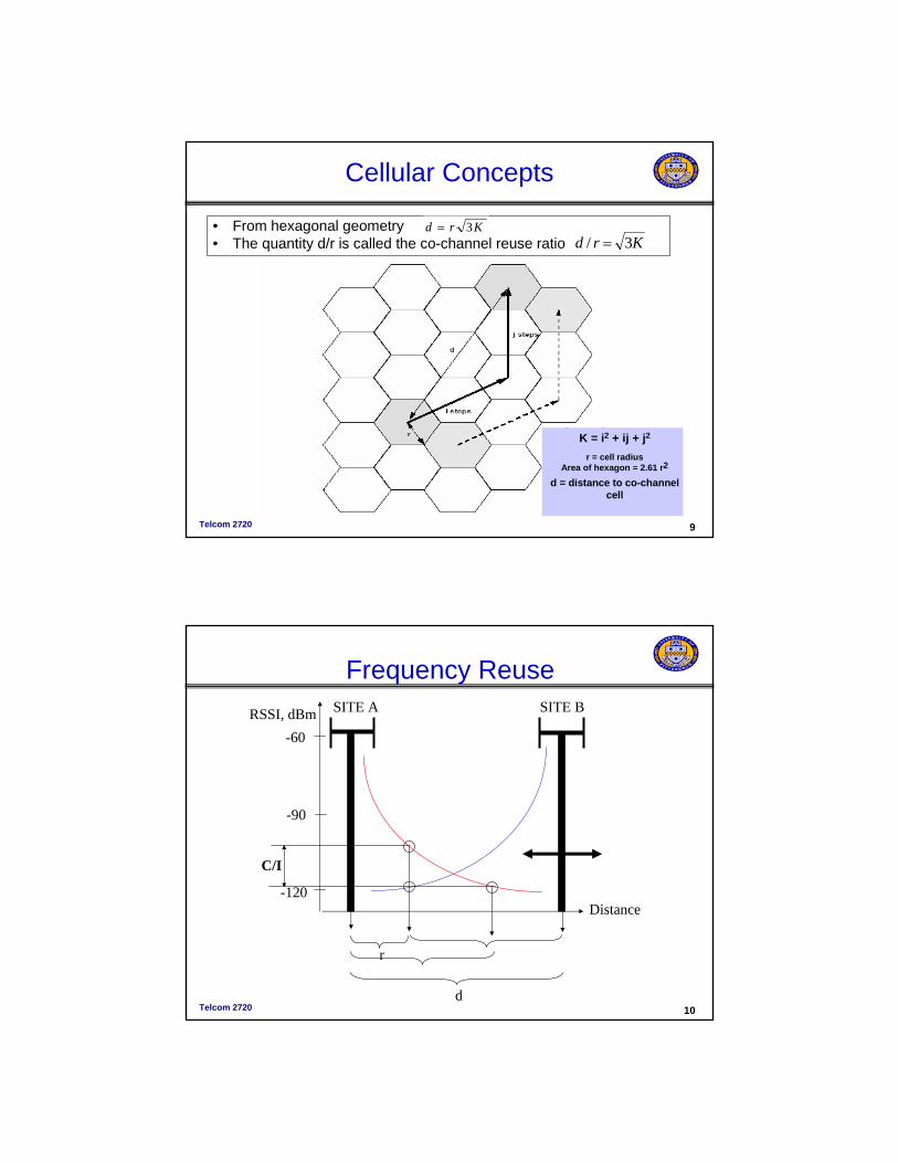
• From hexagonal geometry • The quantity d/r is called the co-channel reuse ratio
K = i2 + ij + j2
r = cell radiusArea of hexagon = 2.61 r2
d = distance to co-channel cell
Krd 3=Krd 3/ =
Telcom 2720 10
Frequency ReuseSITE A SITE BRSSI, dBm
C/I
Distance
r
d
-60
-90
-120
Telcom 2720 11
Frequency Reuse
A
B
B
AB
A
B
A A
B
A
B
A
B
K = 19
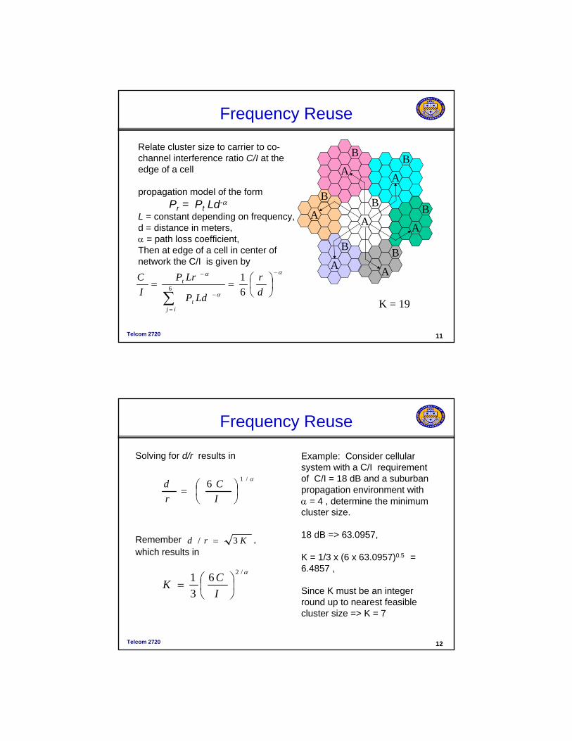
Relate cluster size to carrier to co-channel interference ratio C/I at the edge of a cell
propagation model of the form Pr = Pt Ld-α
L = constant depending on frequency,d = distance in meters,α = path loss coefficient, Then at edge of a cell in center of network the C/I is given by
α
α
α −
−
=
−
⎟⎠⎞
⎜⎝⎛==
∑ dr
LdP
LrPIC
tij
t
61
6
Telcom 2720 12
Frequency Reuse
Solving for d/r results in
Remember , which results in
α/16⎟⎠⎞
⎜⎝⎛=
IC
rd
Example: Consider cellular system with a C/I requirement of C/I = 18 dB and a suburban propagation environment with α = 4 , determine the minimum cluster size.
18 dB => 63.0957,
K = 1/3 x (6 x 63.0957)0.5 = 6.4857 ,
Since K must be an integer round up to nearest feasible cluster size => K = 7
α/2631
⎟⎠⎞
⎜⎝⎛=
ICK
Krd 3/ =
Telcom 2720 13
Frequency Reuse
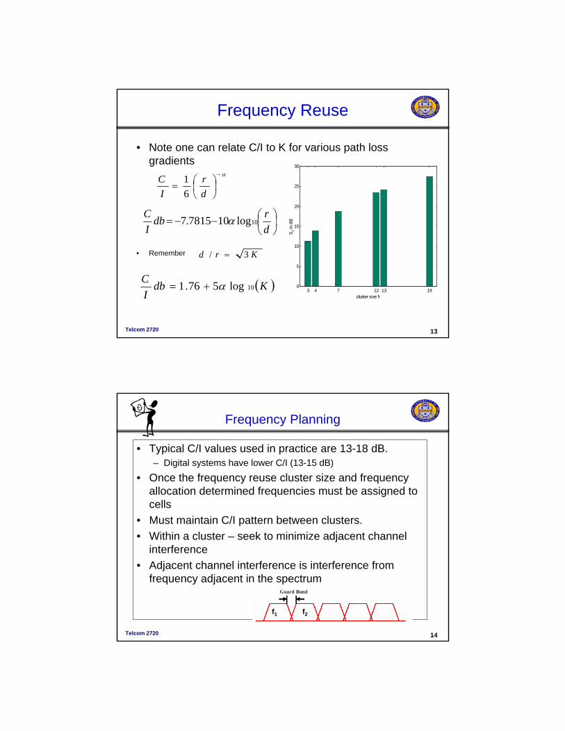
• Note one can relate C/I to K for various path loss gradients
• Remember
α−
⎟⎠⎞
⎜⎝⎛=
dr
IC
61
⎟⎠⎞
⎜⎝⎛−−=drdb
IC
10log107815.7 α
( )KdbIC
10log576.1 α+=
Krd 3/ =
3 4 7 12 13 190
5
10
15
20
25
30
cluster size NS
r in
dB
Telcom 2720 14
Frequency Planning
• Typical C/I values used in practice are 13-18 dB.– Digital systems have lower C/I (13-15 dB)
• Once the frequency reuse cluster size and frequency allocation determined frequencies must be assigned to cells
• Must maintain C/I pattern between clusters.• Within a cluster – seek to minimize adjacent channel
interference• Adjacent channel interference is interference from
frequency adjacent in the spectrum
f2f1
Telcom 2720 15
Frequency Assignment
• Typical C/I values used in practice are 13-18 dB.
• Once the frequency reuse cluster size and frequency allocation determined frequencies must be assigned to cells
• Must maintain C/I pattern between clusters.
• Within a cluster – seek to minimize adjacent channel interference
• Adjacent channel interference is interference from frequency adjacent in the spectrum
Example: You are operating a cellular network with 25KHz NMT traffic channels 1 through 12. Labeling the traffic channels as {f1, f2, f3, f4, f5, f6, f7, f8, f9, f10, f11, f12} Place the traffic channels in the cells below such that a frequency reuse cluster size of 4 is used and adjacent channel interference is minimized
Telcom 2720 16
Sectoring
12
32
13
120 sectoring
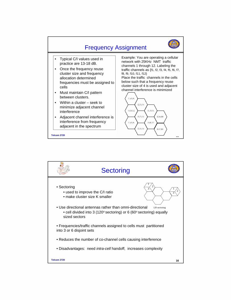
• Sectoring • used to improve the C/I ratio • make cluster size K smaller
• Use directional antennas rather than omni-directional• cell divided into 3 (120o sectoring) or 6 (60o sectoring) equally sized sectors
• Frequencies/traffic channels assigned to cells must partitioned into 3 or 6 disjoint sets
• Reduces the number of co-channel cells causing interference
• Disadvantages: need intra-cell handoff, increases complexity
Telcom 2720 17
Sectoring
43
52
16
75
5
5
55
5
12
32
13
120 sectoring
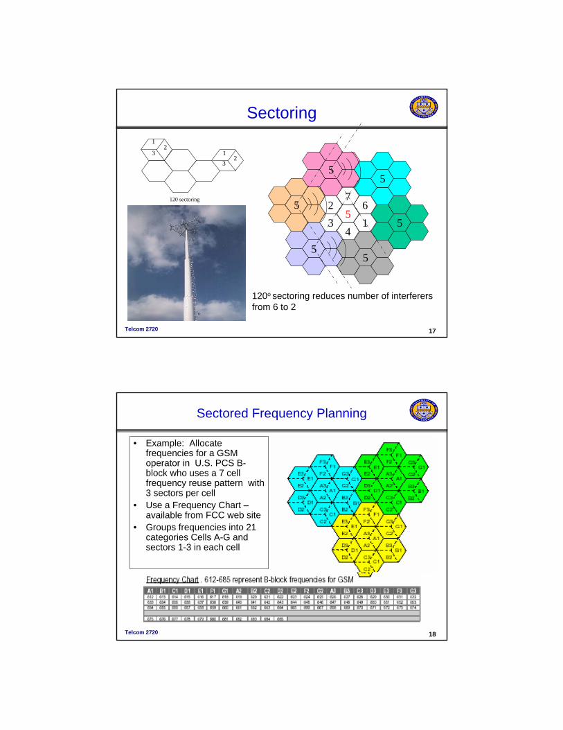
120o sectoring reduces number of interferers from 6 to 2
Telcom 2720 18
Sectored Frequency Planning
• Example: Allocate frequencies for a GSM operator in U.S. PCS B-block who uses a 7 cell frequency reuse pattern with 3 sectors per cell
• Use a Frequency Chart –available from FCC web site
• Groups frequencies into 21 categories Cells A-G and sectors 1-3 in each cell
Telcom 2720 19
Sectored Frequency Planning
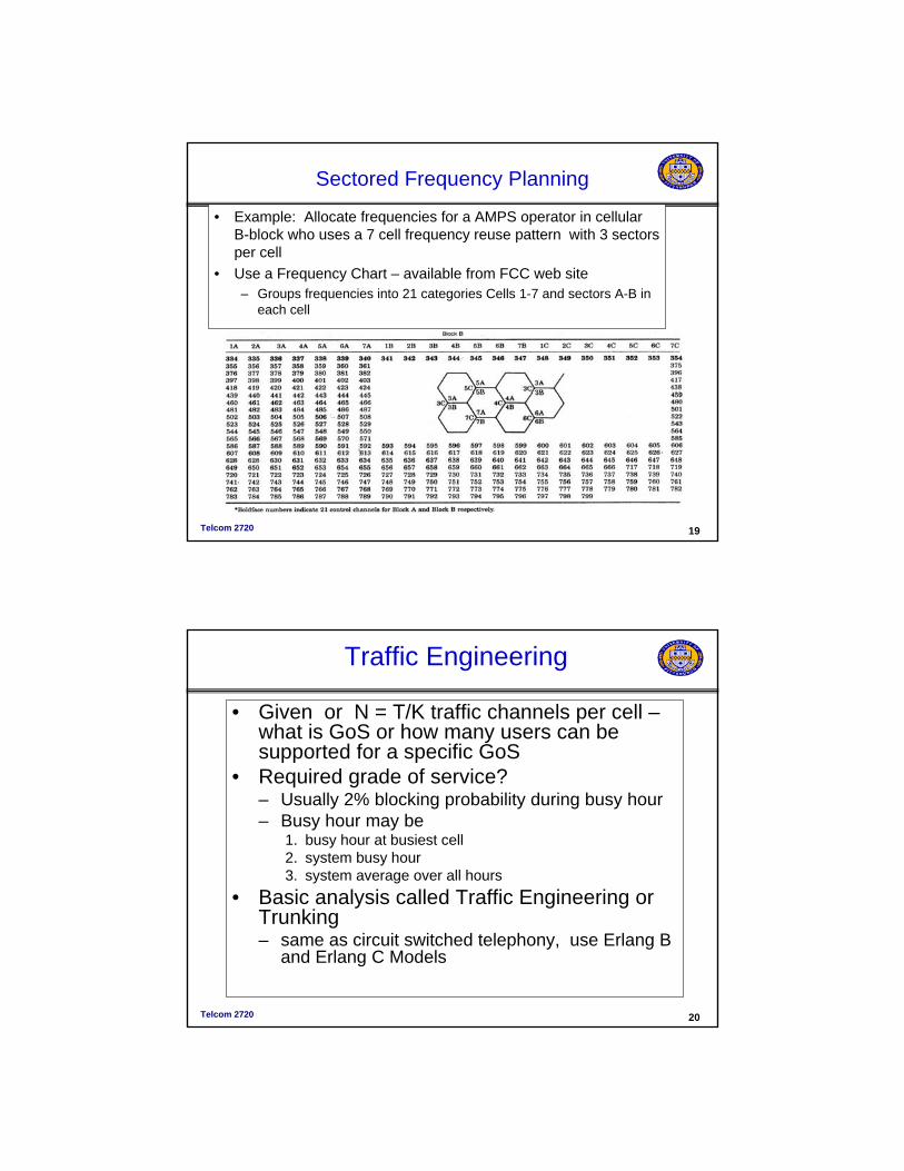
• Example: Allocate frequencies for a AMPS operator in cellular B-block who uses a 7 cell frequency reuse pattern with 3 sectors per cell
• Use a Frequency Chart – available from FCC web site– Groups frequencies into 21 categories Cells 1-7 and sectors A-B in
each cell
Telcom 2720 20
Traffic Engineering
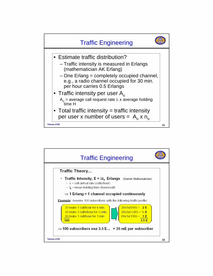
• Given or N = T/K traffic channels per cell –what is GoS or how many users can be supported for a specific GoS
• Required grade of service?– Usually 2% blocking probability during busy hour– Busy hour may be
1. busy hour at busiest cell 2. system busy hour 3. system average over all hours
• Basic analysis called Traffic Engineering or Trunking– same as circuit switched telephony, use Erlang B
and Erlang C Models
Telcom 2720 21
Traffic Engineering
• Estimate traffic distribution?– Traffic intensity is measured in Erlangs
(mathematician AK Erlang)– One Erlang = completely occupied channel,
e.g., a radio channel occupied for 30 min. per hour carries 0.5 Erlangs
• Traffic intensity per user AuAu = average call request rate λ x average holding
time H
• Total traffic intensity = traffic intensity per user x number of users = Au x nu
Telcom 2720 22
Traffic Engineering
Telcom 2720 23
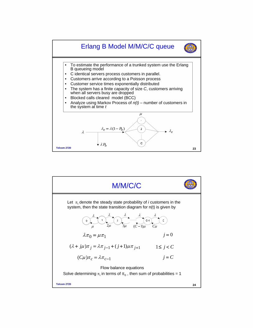
Erlang B Model M/M/C/C queue
• To estimate the performance of a trunked system use the ErlangB queueing model
• C identical servers process customers in parallel.• Customers arrive according to a Poisson process• Customer service times exponentially distributed• The system has a finite capacity of size C, customers arriving
when all servers busy are dropped • Blocked calls cleared model (BCC)• Analyze using Markov Process of n(t) – number of customers in
the system at time t
λ
μ
)1( be P−= λλ
bPλ
eλ
Telcom 2720 24
M/M/C/C
λλλ λλ
μ3μ2μ μCμ)1( −C
Cj <≤111 )1()( +− ++=+ jjj jj μπλππμλ
10 μπλπ = 0=j
Cj =1)( −= ccC λππμ
Let πi denote the steady state probability of i customers in the system, then the state transition diagram for n(t) is given by
Flow balance equationsSolve determining πi in terms of π0 , then sum of probabilities = 1
Telcom 2720 25
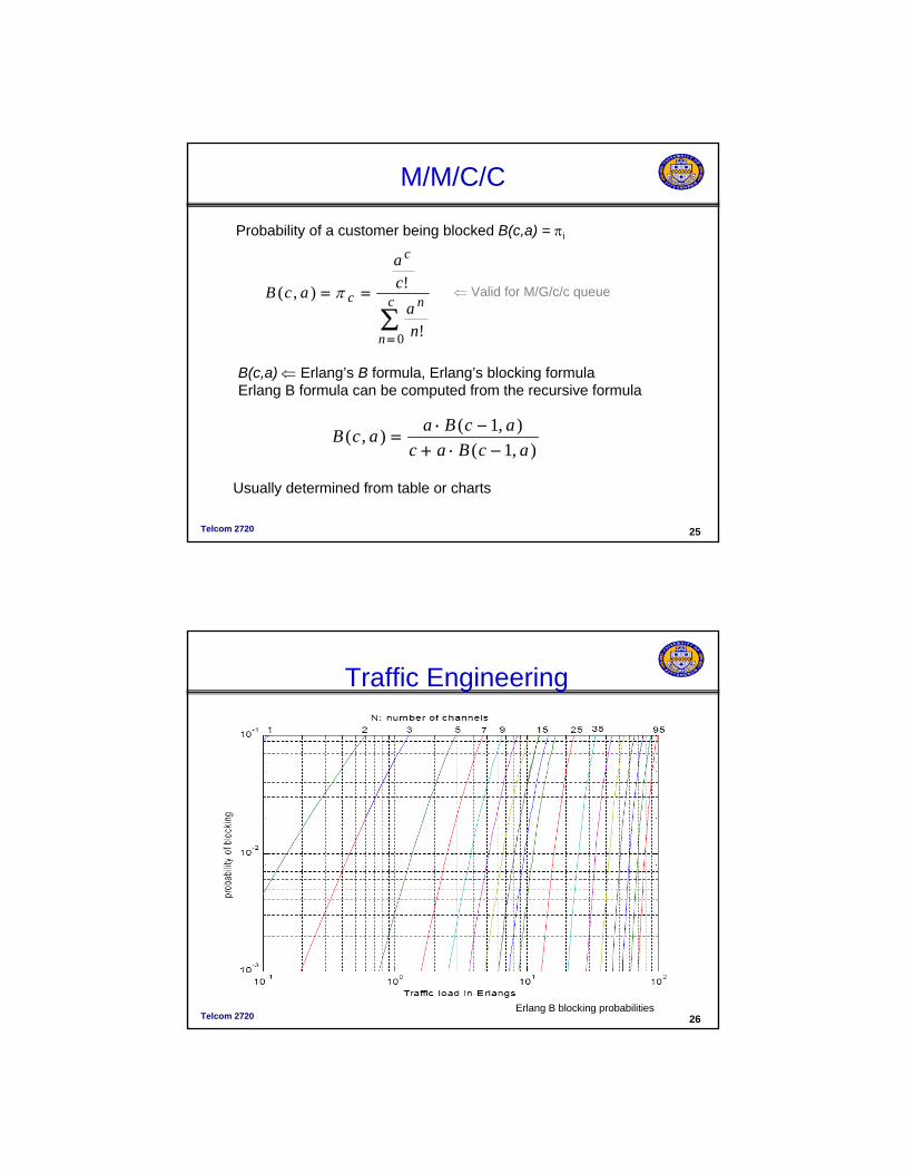
M/M/C/C
∑=
== c
n
n
c
c
na
ca
acB
0 !
!),( π
Probability of a customer being blocked B(c,a) = πi
B(c,a) ⇐ Erlang’s B formula, Erlang’s blocking formulaErlang B formula can be computed from the recursive formula
⇐ Valid for M/G/c/c queue
),1(),1(),(acBac
acBaacB−⋅+
−⋅=
Usually determined from table or charts
Telcom 2720 26
Traffic Engineering
Erlang B blocking probabilities
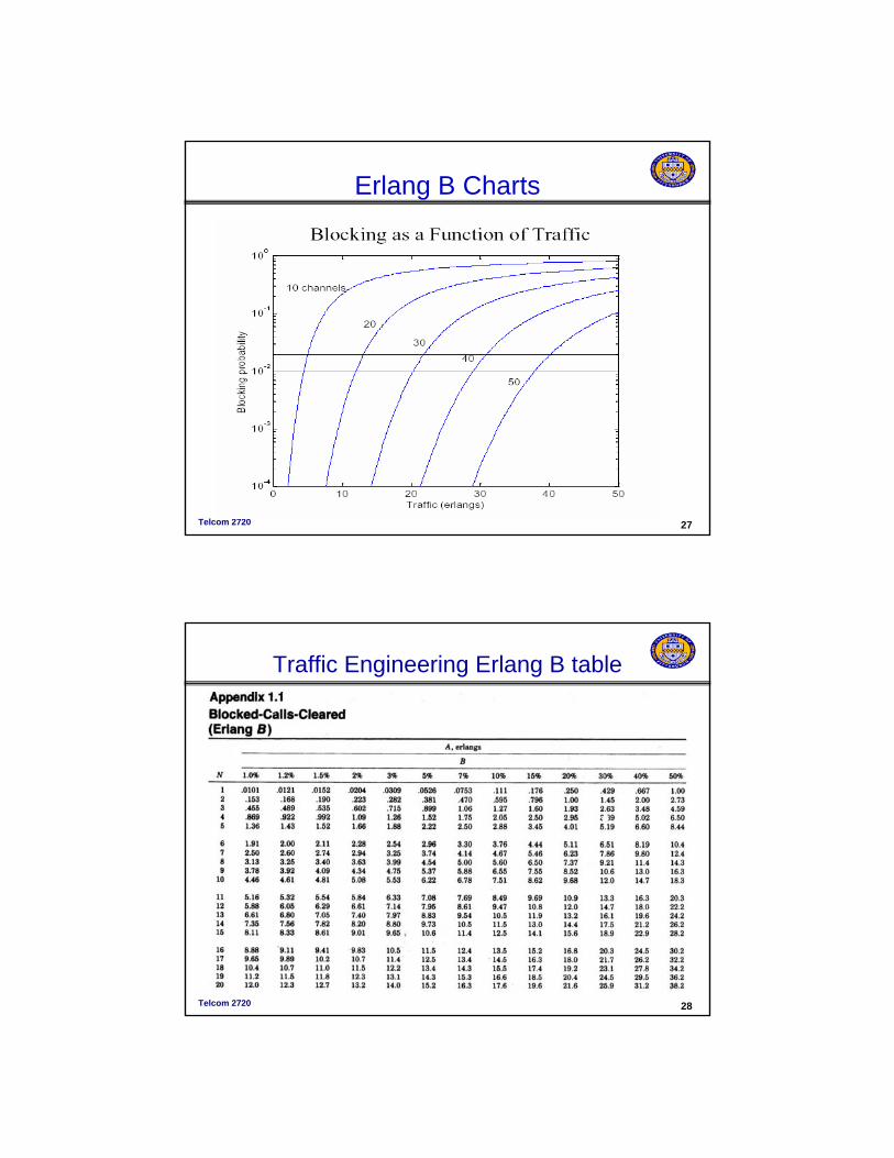
Telcom 2720 27
Erlang B Charts
Telcom 2720 28
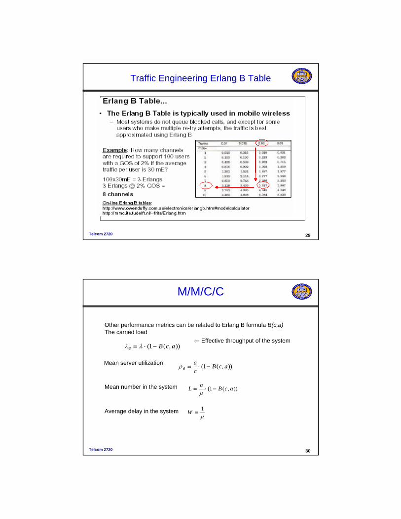
Traffic Engineering Erlang B table
Telcom 2720 29
Traffic Engineering Erlang B Table
Telcom 2720 30
M/M/C/C
)),(1( acBe −⋅= λλ
)),(1( acBca
e −⋅=ρ
)),(1( acBaL −⋅=μ
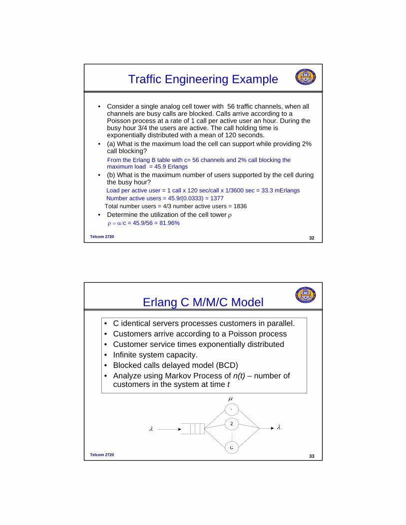
Other performance metrics can be related to Erlang B formula B(c,a)The carried load
⇐ Effective throughput of the system
Mean server utilization
Mean number in the system
Average delay in the systemμ1
=W
Telcom 2720 32
Traffic Engineering Example
• Consider a single analog cell tower with 56 traffic channels, when all channels are busy calls are blocked. Calls arrive according to aPoisson process at a rate of 1 call per active user an hour. During the busy hour 3/4 the users are active. The call holding time is exponentially distributed with a mean of 120 seconds.
• (a) What is the maximum load the cell can support while providing 2% call blocking?From the Erlang B table with c= 56 channels and 2% call blocking the maximum load = 45.9 Erlangs
• (b) What is the maximum number of users supported by the cell during the busy hour? Load per active user = 1 call x 120 sec/call x 1/3600 sec = 33.3 mErlangsNumber active users = 45.9/(0.0333) = 1377
Total number users = 4/3 number active users = 1836• Determine the utilization of the cell tower ρ
ρ = α/c = 45.9/56 = 81.96%
Telcom 2720 33
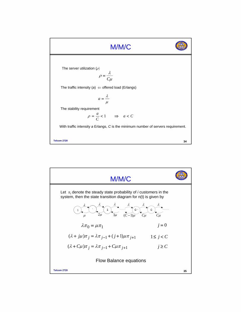
Erlang C M/M/C Model• C identical servers processes customers in parallel.• Customers arrive according to a Poisson process• Customer service times exponentially distributed• Infinite system capacity.• Blocked calls delayed model (BCD)• Analyze using Markov Process of n(t) – number of
customers in the system at time t
λ
μ
λ
Telcom 2720 34
M/M/C
μλ
=a
μλρ
C=
The server utilization (ρ)
The traffic intensity (a) ⇐ offered load (Erlangs)
The stability requirement
CaCa
<⇒<= 1ρ
With traffic intensity a Erlangs, C is the minimum number of servers requirement.
Telcom 2720 35
M/M/C
μ3μ μCμCμ)1( −C
λλ
μ2
λ λλλ
Cj <≤111 )1()( +− ++=+ jjj jj μπλππμλ
10 μπλπ = 0=j
Cj ≥11)( +− +=+ jjj CC μπλππμλ
Let πi denote the steady state probability of i customers in the system, then the state transition diagram for n(t) is given by
Flow Balance equations
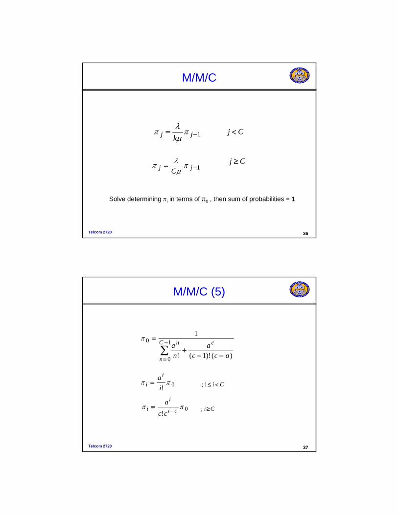
Telcom 2720 36
M/M/C
1−= jj kπ
μλπ Cj <
Cj ≥1−= jj C
πμ
λπ
Solve determining πi in terms of π0 , then sum of probabilities = 1
Telcom 2720 37
M/M/C (5)
Cii
i ia
<≤= 1;0!ππ
∑−
= −−+
= 1
0
0
)()!1(!
1C
n
cn
acca
na
π
Cici
ii
cca
≥−= ;0!
ππ
Telcom 2720 38
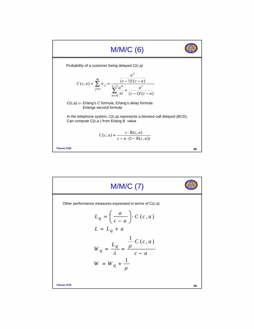
M/M/C (6)
∑∑ −
=
∞
=−−
+
−−== 1
0 )()!1(!
)()!1(),( c
n
cn
c
cjj
acca
na
acca
acC π
Probability of a customer being delayed C(c,a)
C(c,a) ⇐ Erlang’s C formula, Erlang’s delay formulaErlangs second formula
In the telephone system, C(c,a) represents a blocked call delayed (BCD).Can compute C(c,a ) from Erlang B value
)),(1(),(),(
acBacacBcacC
−⋅−⋅
=
Telcom 2720 39
M/M/C (7)
μ
μλ
1
),(1
),(
+=
−==
+=
⋅⎟⎠⎞
⎜⎝⎛
−=
q
q
q
WW
ac
acCLW
aLL
acCac
aL
Other performance measures expressed in terms of C(c,a)
Telcom 2720 40
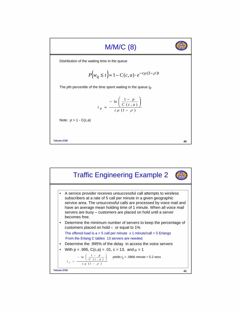
M/M/C (8)
)1(),(
1ln
ρμ −
⎟⎟⎠
⎞⎜⎜⎝
⎛ −−
=c
acCp
t p
Distribution of the waiting time in the queue
The pth percentile of the time spent waiting in the queue tp
{ } tcq eacCtwP )1(),(1 ρμ −−⋅−=≤
Note: p > 1 - C(c,a)
Telcom 2720 41
Traffic Engineering Example 2
• A service provider receives unsuccessful call attempts to wireless subscribers at a rate of 5 call per minute in a given geographicservice area. The unsuccessful calls are processed by voice mail and have an average mean holding time of 1 minute. When all voice mail servers are busy – customers are placed on hold until a server becomes free.
• Determine the minimum number of servers to keep the percentage of customers placed on hold < or equal to 1% The offered load is a = 5 call per minute x 1 minute/call = 5 ErlangsFrom the Erlang C tables 13 servers are needed.
• Determine the .995% of the delay in access the voice servers • With p = .995, C(c,a) = .01, c = 13, and μ = 1
)1(),(
1ln
ρμ −
⎟⎟⎠
⎞⎜⎜⎝
⎛ −−=
cacCp
t p
yields tp = .0866 minute = 5.2 secs
Telcom 2720 42
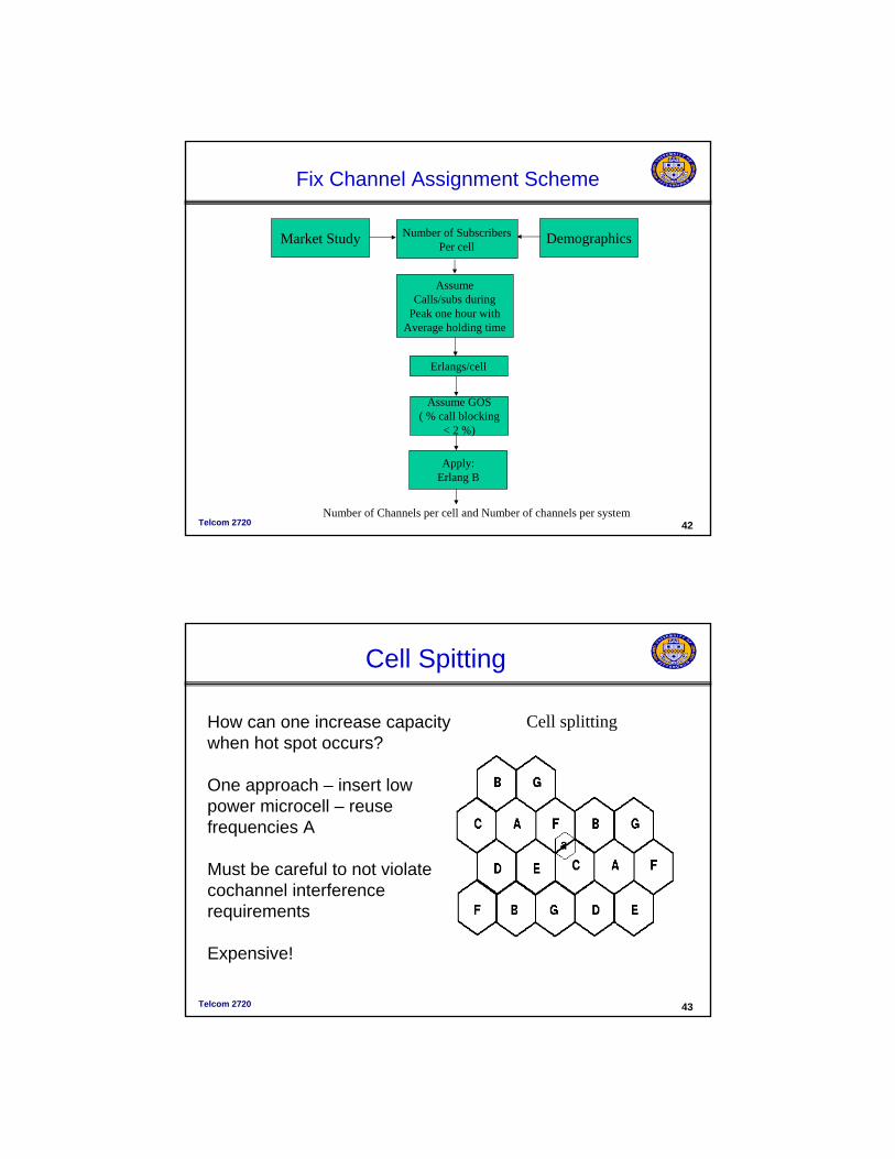
Fix Channel Assignment Scheme
Market Study Demographics
AssumeCalls/subs during
Peak one hour withAverage holding time
Number of SubscribersPer cell
Erlangs/cell
Assume GOS( % call blocking
< 2 %)
Apply:Erlang B
Number of Channels per cell and Number of channels per system
Telcom 2720 43
Cell splitting
Cell Spitting
How can one increase capacity when hot spot occurs?
One approach – insert low power microcell – reuse frequencies A
Must be careful to not violate cochannel interference requirements
Expensive!
Telcom 2720 44
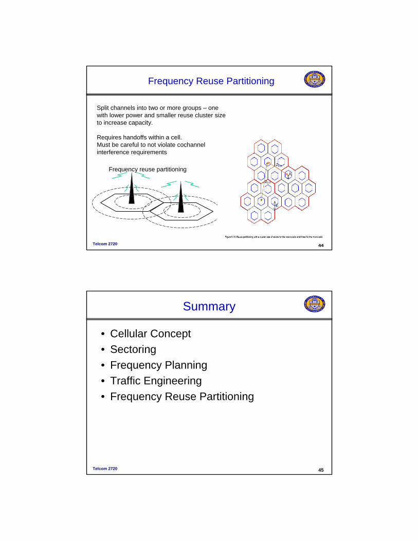
Frequency Reuse Partitioning
Split channels into two or more groups – one with lower power and smaller reuse cluster size to increase capacity.
Requires handoffs within a cell. Must be careful to not violate cochannelinterference requirements
Frequency reuse partitioning
Telcom 2720 45
Summary
• Cellular Concept• Sectoring • Frequency Planning• Traffic Engineering• Frequency Reuse Partitioning