Embed Size (px)
DESCRIPTION
Functions of a Pump. Transfer fluid between two points. Produce required flow rate. Produce required pressure. Pump - Facts. Pump changes both velocity and pressure of the fluid. Pump only adds to the system energy. - PowerPoint PPT Presentation
Citation preview
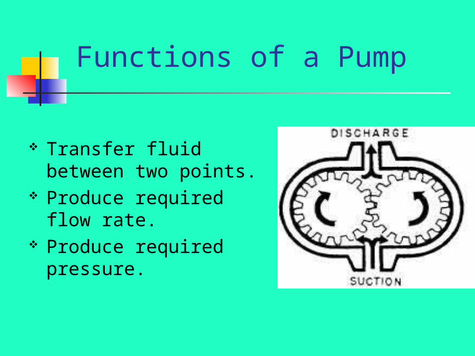
Functions of a Pump
Transfer fluid between two points.
Produce required flow rate.
Produce required pressure.
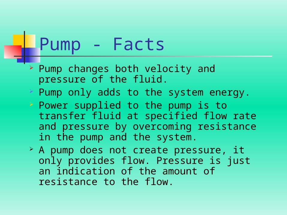
Pump - Facts Pump changes both velocity and pressure
of the fluid. Pump only adds to the system energy. Power supplied to the pump is to transfer
fluid at specified flow rate and pressure by overcoming resistance in the pump and the system.
A pump does not create pressure, it only provides flow. Pressure is just an indication of the amount of resistance to the flow.
Viscosity of the fluid pumped must be within the range specified in the pump design.
Reciprocating Displacement pumps can handle any required viscosity.
Rotary Positive Displacement Pumps ( Common- Gear and Screw ) are used for intermediate range of viscosities.
Centrifugal Pumps are used for Medium to Low range of viscosities.
Onboard ships, permission should be obtained before any fluids are moved, which might affect the stability of the ship.
Pumps and Viscosity of Fluid Handled.
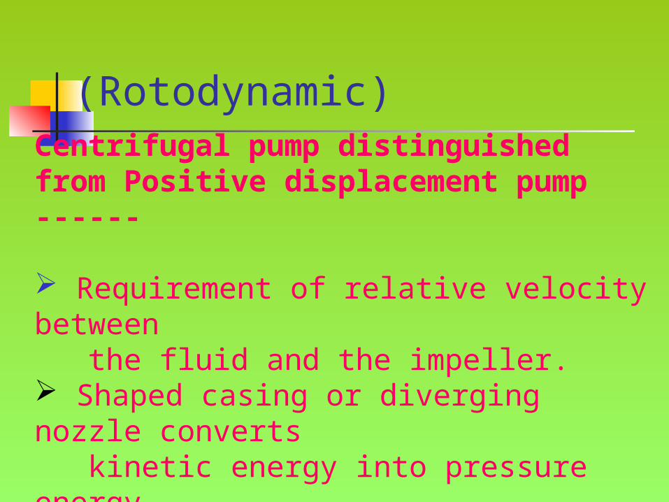
Centrifugal Pump (Rotodynamic)
Centrifugal pump distinguished from Positive displacement pump ------
Requirement of relative velocity between the fluid and the impeller. Shaped casing or diverging nozzle converts kinetic energy into pressure energy. Liquid in the impeller and casing essential for pump operation.
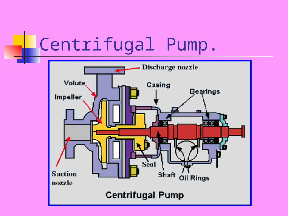
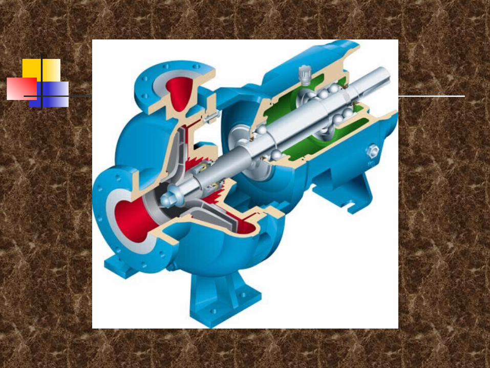
Centrifugal Pump.

The energy changes occur in a centrifugal pump by virtue of two main parts of the pump.The Impeller – The rotating part that converts driver energy into kinetic energy.The volute or Diffuser – The stationary part that converts the kinetic energy into pressure energy.The process liquid enters the suction nozzle and then into the eye of the impeller. Impeller spins the liquid sitting in the cavities between the vanes, outwards and provides centrifugal acceleration. As liquid leaves the eye of the impeller, a low pressure area is created, causing more liquid to flow towards the inlet. Because the impeller blades are curved, the fluid is pushed in a tangential and radial direction by the centrifugal forces.
Centrifugal Pump- Theory
The process liquid enters the suction nozzle and then into the eye of the impeller. Impeller spins the liquid sitting in the cavities between the vanes, outwards and provides centrifugal acceleration. As liquid leaves the eye of the impeller, a low pressure area is created, causing more liquid to flow towards the inlet. Because the impeller blades are curved, the fluid is pushed in a tangential and radial direction by the centrifugal forces.
Centrifugal Pump- Theory
Centrifugal Pump - TheoryThe amount of energy given to the liquid is
proportional to the velocity at the edge or vane tip
of the impeller. The faster the impeller revolves or
bigger the impeller is, then higher will be the
velocity of the liquid at the vane tip and greater the
energy imparted to the liquid.

Centrifugal Pump – Theory.
The kinetic energy of a liquid coming out of an
impeller is harnessed by creating a resistance to the
flow. The first resistance is created by pump volute
casing, which catches the liquid and slows it down. In
the discharge nozzle, the liquid further decelerates
and its velocity is converted to pressure.
Centrifugal Pump - HeadThe pressure at any point in a liquid can be thought of as being caused by a vertical column of the liquid due to its weight. The height of this column is called the static head and is expressed in terms of meters of liquid. Head is a measurement of height of a liquid column that a pump could create from kinetic energy imparted to the liquid. Imagine a pipe shooting a jet of water straight up into the air, the height the water goes up would be the head.
Centrifugal Pump - Vapour Pressure
Vapor pressure is the pressure at which a liquid and its vapor co-exist in equilibrium, at a given temperature. Vaporization begins when the vapor pressure of the liquid at the operating temperature equals the external system pressure, which in an open system always equal to the atmospheric pressure. Any decrease in external pressure or rise in operating temperature can induce vaporization and the pump stops pumping.
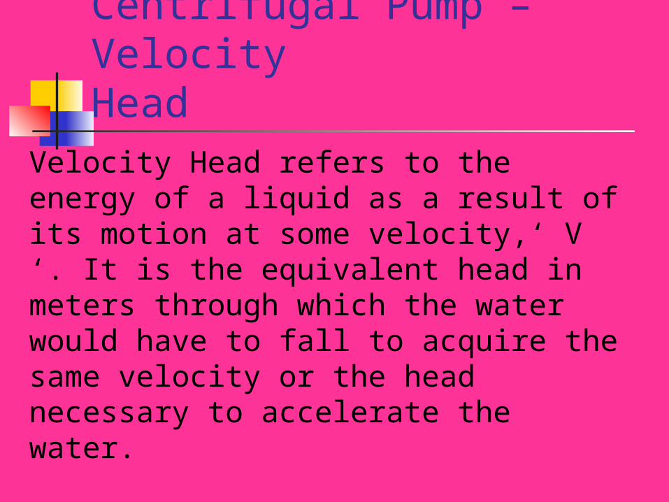
Centrifugal Pump – Velocity Head
Velocity Head refers to the energy of a liquid as a result of its motion at some velocity,‘ V ‘. It is the equivalent head in meters through which the water would have to fall to acquire the same velocity or the head necessary to accelerate the water.
Velocity head is insignificant in most high head systems, but it can be large in low head systems.
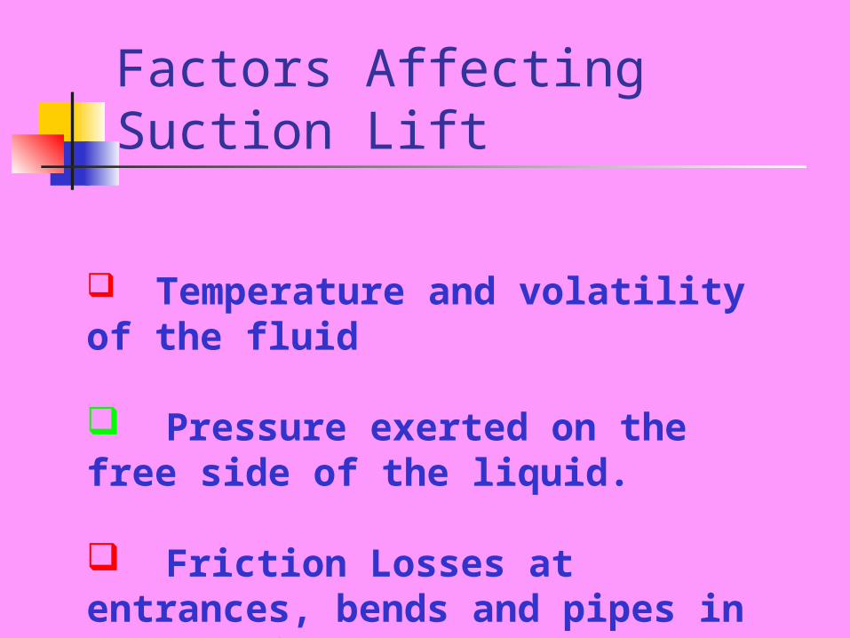
Factors Affecting Suction Lift
Temperature and volatility of the fluid
Pressure exerted on the free side of the liquid.
Friction Losses at entrances, bends and pipes in the suction system.
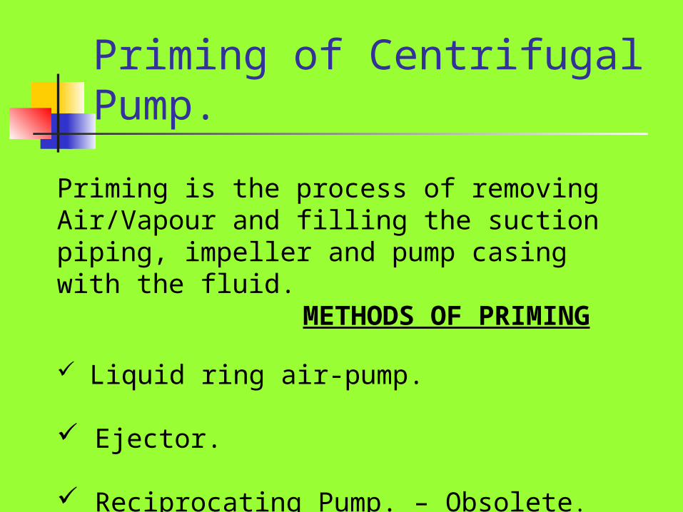
Priming of Centrifugal Pump.
Priming is the process of removing Air/Vapour and filling the suction piping, impeller and pump casing with the fluid. METHODS OF PRIMING
Liquid ring air-pump.
Ejector.
Reciprocating Pump. – Obsolete.
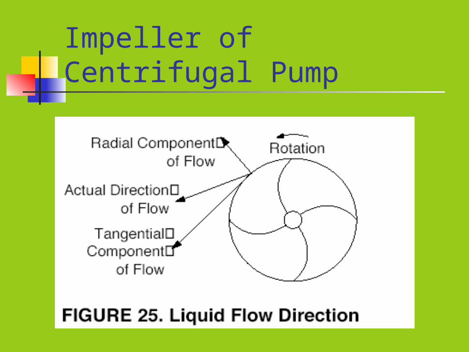
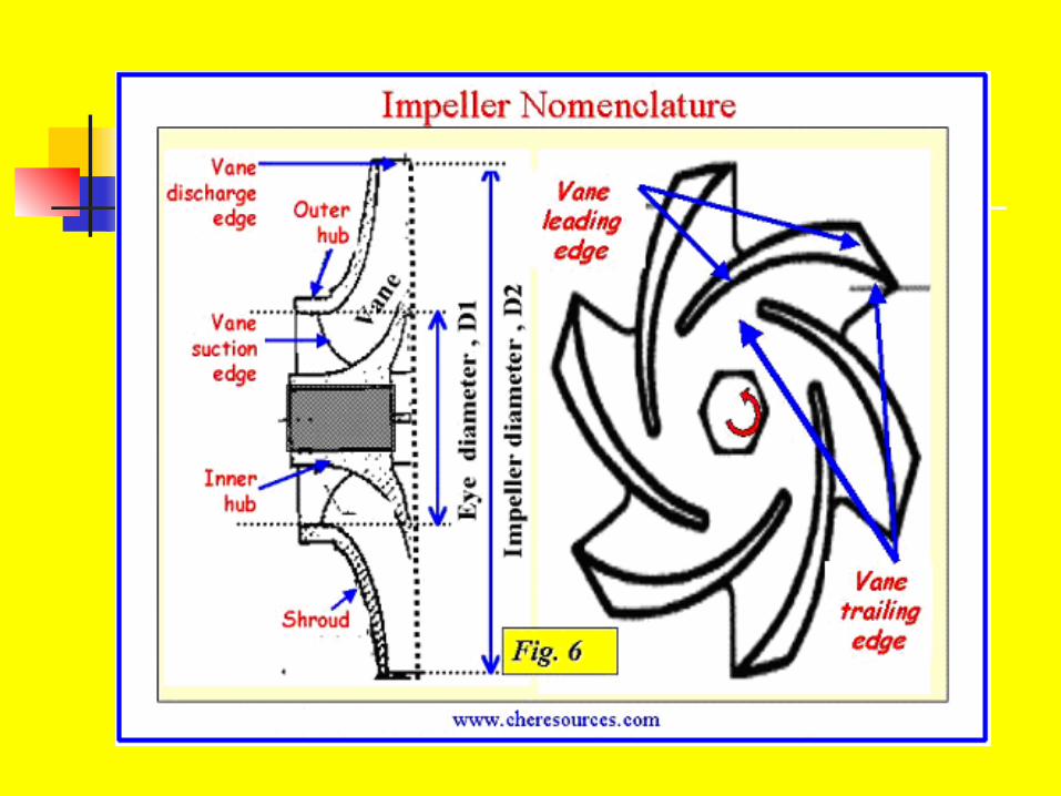
Impeller of Centrifugal Pump
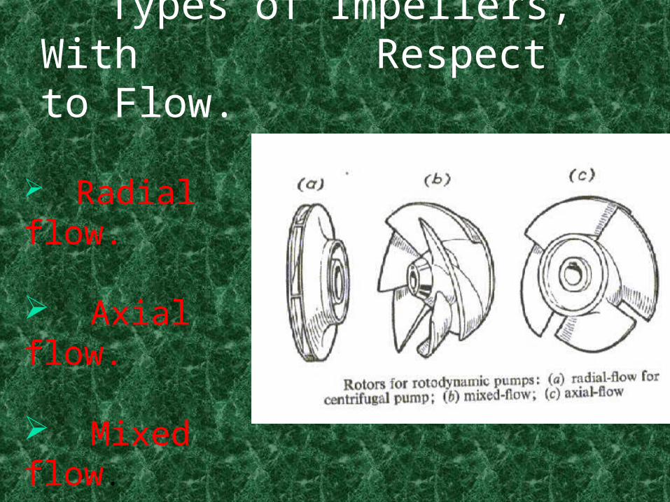
Types of Impellers, With Respect to Flow.
Radial flow.
Axial flow.
Mixed flow.
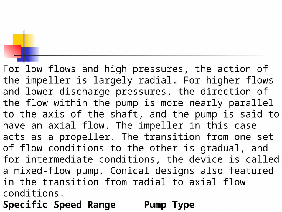
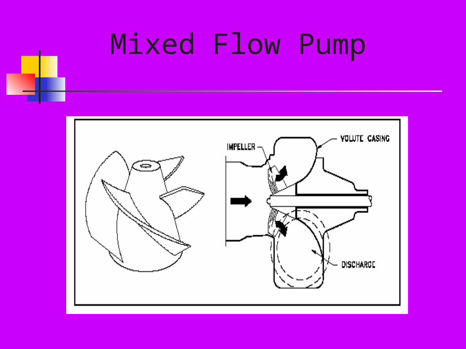
For low flows and high pressures, the action of the impeller is largely radial. For higher flows and lower discharge pressures, the direction of the flow within the pump is more nearly parallel to the axis of the shaft, and the pump is said to have an axial flow. The impeller in this case acts as a propeller. The transition from one set of flow conditions to the other is gradual, and for intermediate conditions, the device is called a mixed-flow pump. Conical designs also featured in the transition from radial to axial flow conditions. Specific Speed Range Pump Type Below 5,000 Radial Flow Pumps 4,000 - 10,000 Mixed Flow Pumps 9,000 - 15,000 Axial Flow Pumps
Types of Impellers With Respect to Construction.
o Open (with partial shrouds for strength. - - For abrasive liquids with suspended solids.
o Semi-Open - - For viscous liquids.
o Enclosed - - For clear liquids.
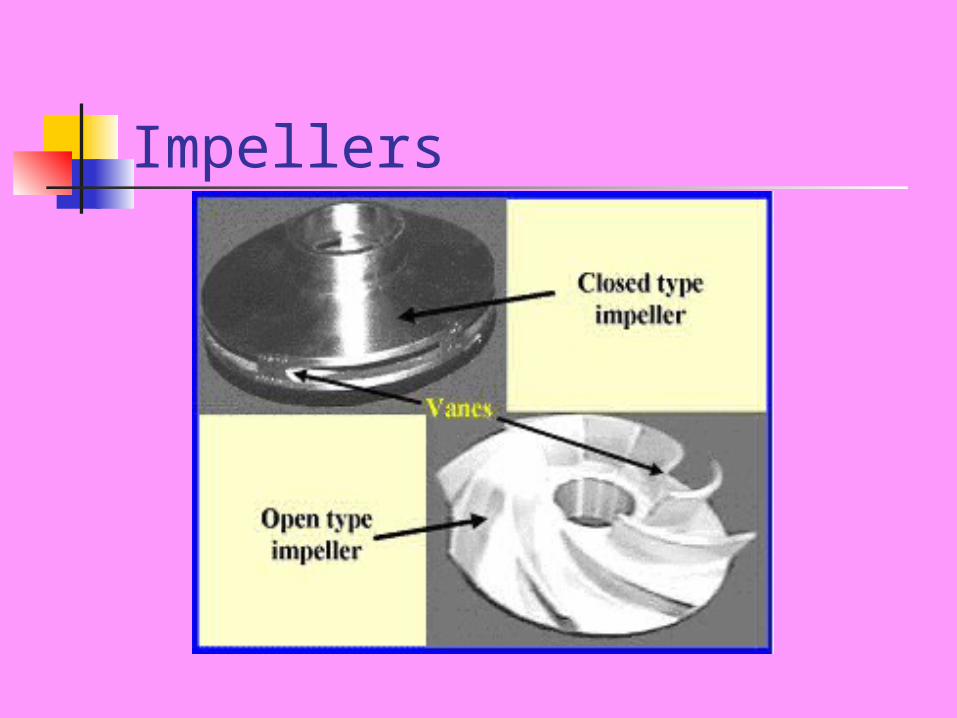
Impellers
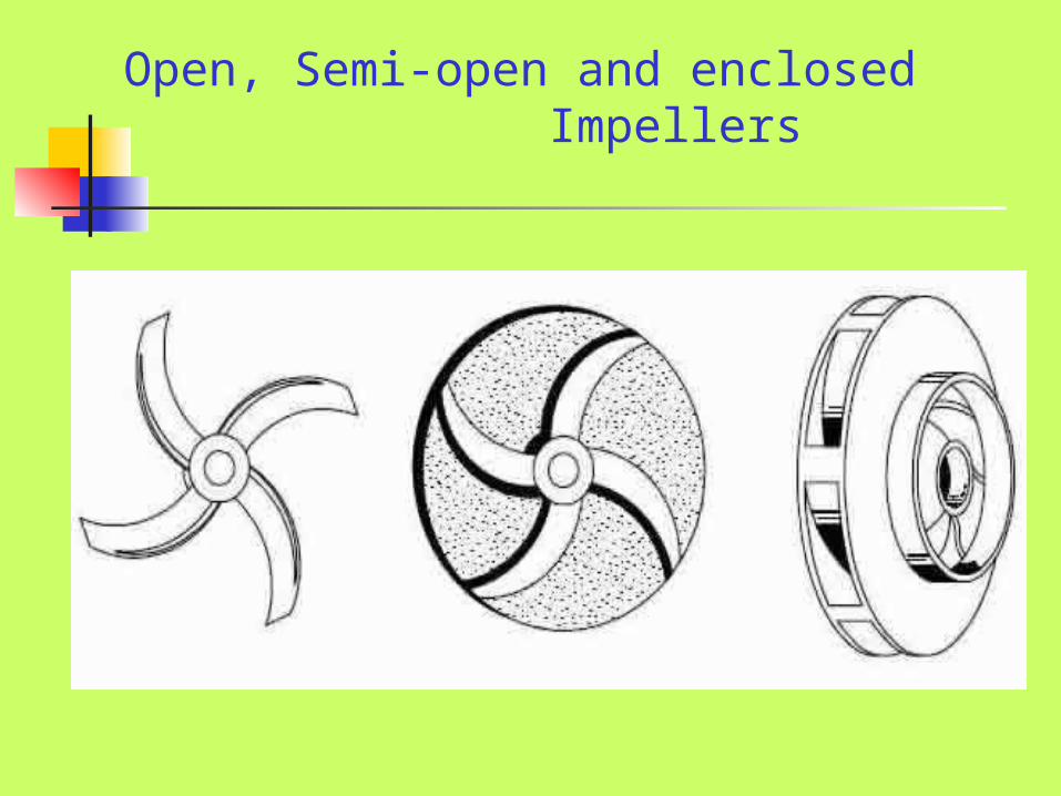
Open, Semi-open and enclosed Impellers
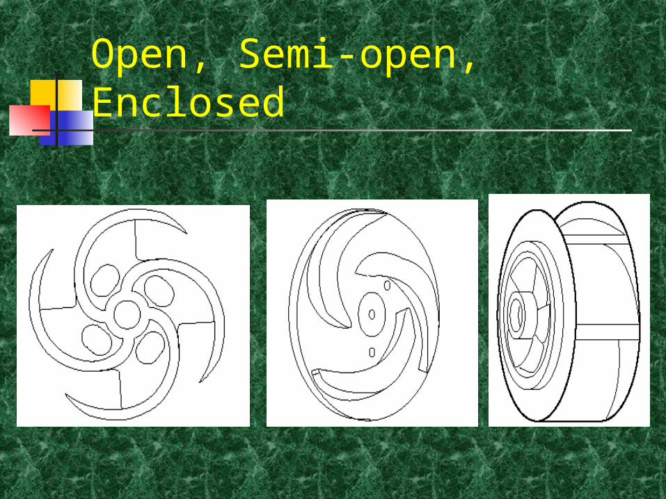
Open, Semi-open, Enclosed
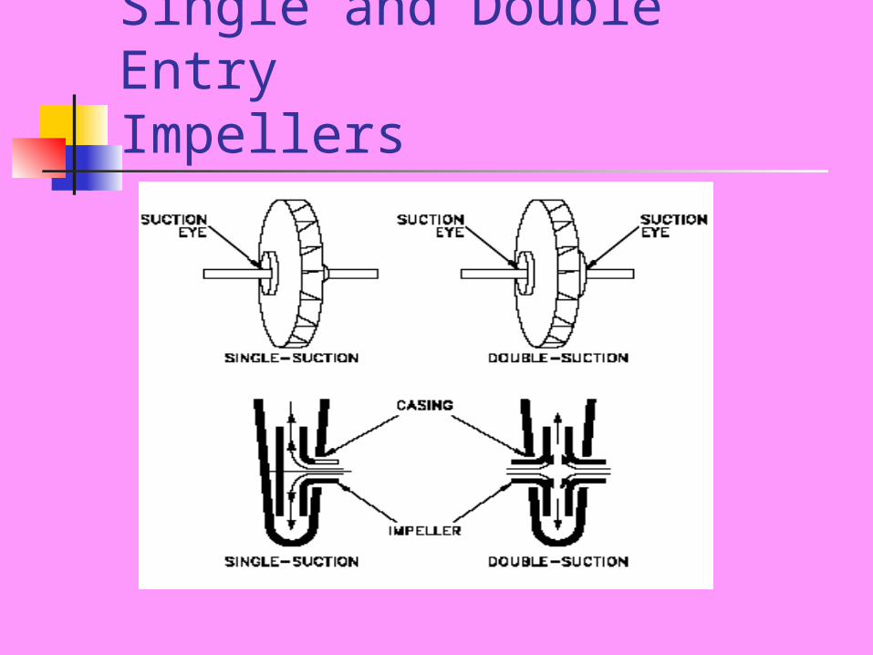
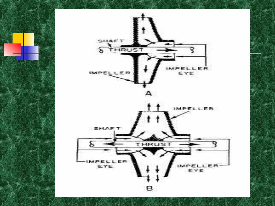
Single and Double Entry Impellers

Types of Centrifugal Pumps With Respect to the Construction of the Casing.
Volute
Diffuser
Regenerative
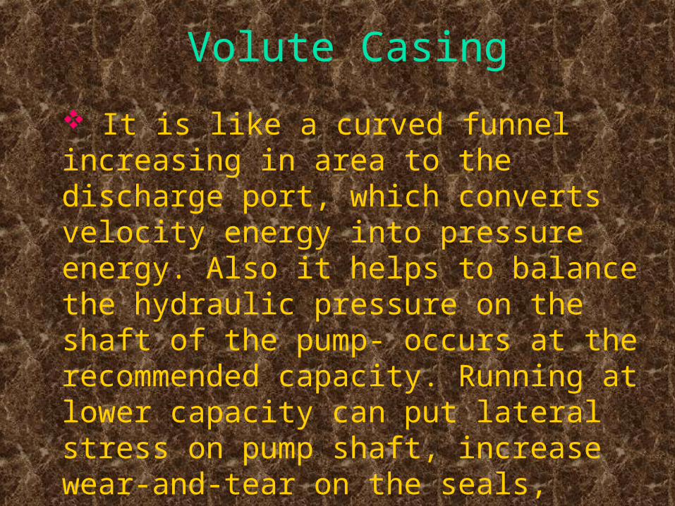
Volute Casing
It is like a curved funnel increasing in area to the discharge port, which converts velocity energy into pressure energy. Also it helps to balance the hydraulic pressure on the shaft of the pump- occurs at the recommended capacity. Running at lower capacity can put lateral stress on pump shaft, increase wear-and-tear on the seals, bearings and on the shaft itself.
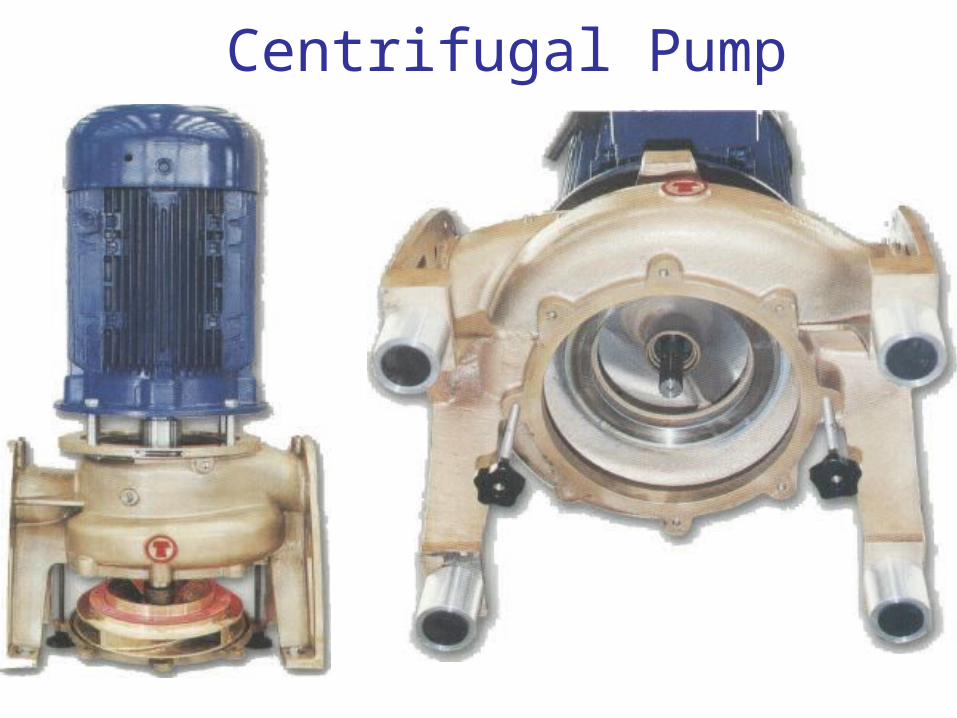
Centrifugal Pump
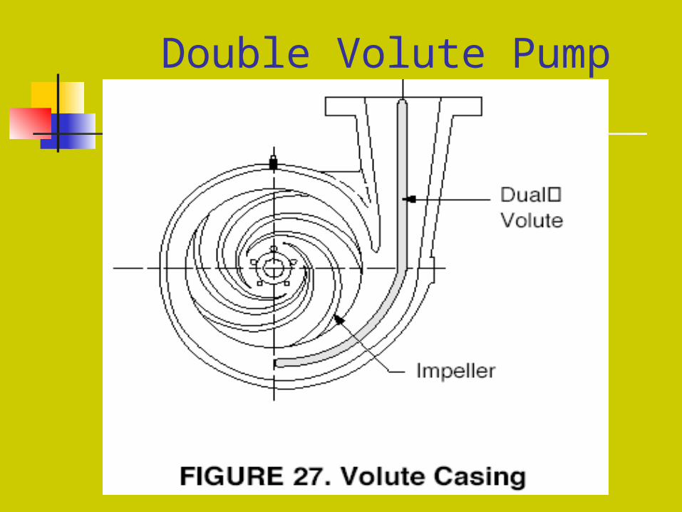
Double Volute Pump
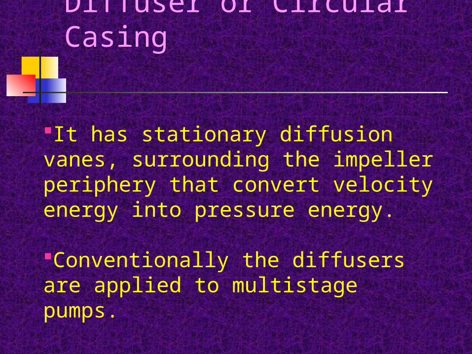
Diffuser or Circular Casing
It has stationary diffusion vanes, surrounding the impeller periphery that convert velocity energy into pressure energy.
Conventionally the diffusers are applied to multistage pumps.
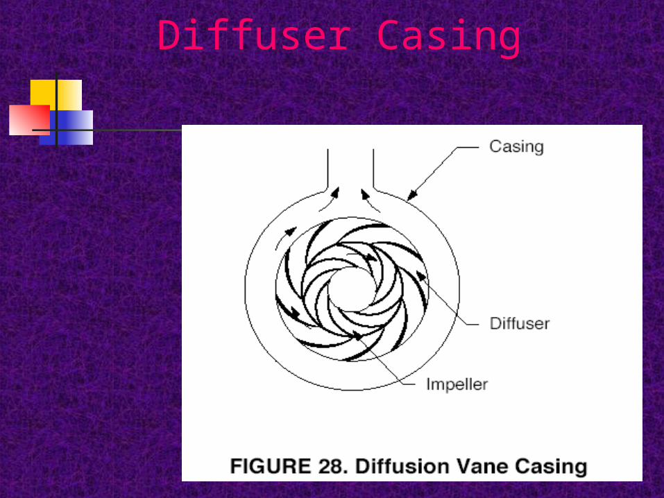
Diffuser Casing
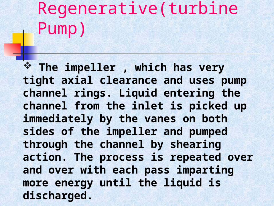
Regenerative(turbine Pump)
The impeller , which has very tight axial clearance and uses pump channel rings. Liquid entering the channel from the inlet is picked up immediately by the vanes on both sides of the impeller and pumped through the channel by shearing action. The process is repeated over and over with each pass imparting more energy until the liquid is discharged.
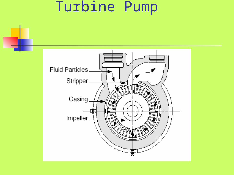
Turbine Pump
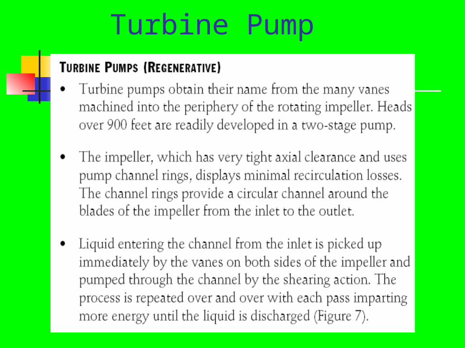
Turbine Pump
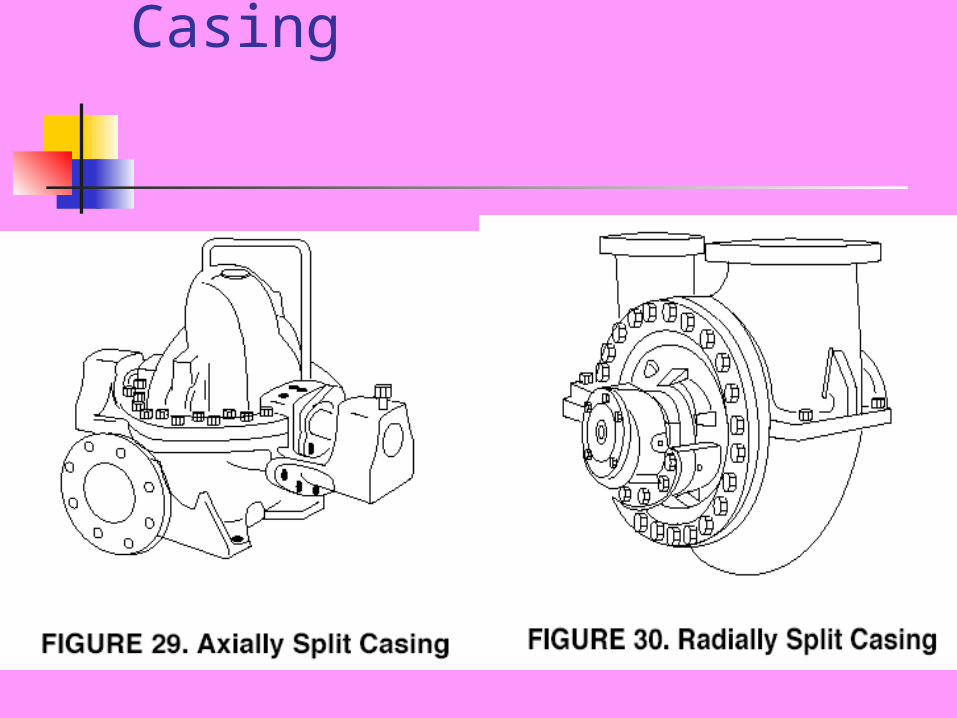
Axially/Radially Split Casing
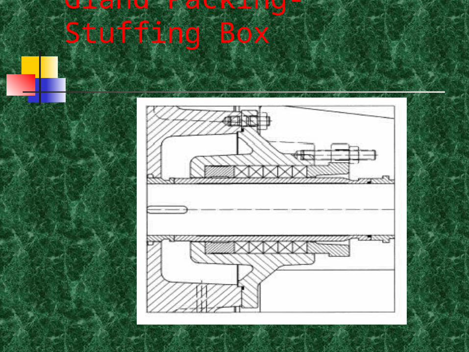
Gland Packing- Stuffing Box
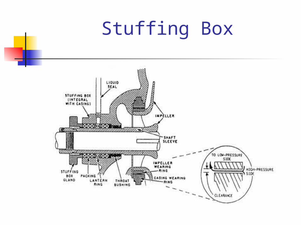
Stuffing Box
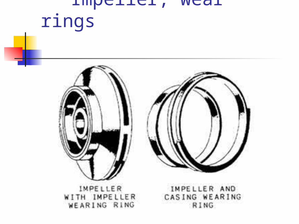
Impeller, wear rings
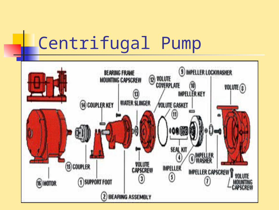
Centrifugal Pump
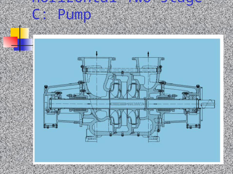
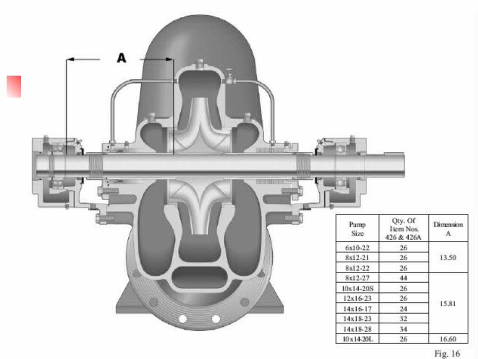
Horizontal Two-stage C: Pump
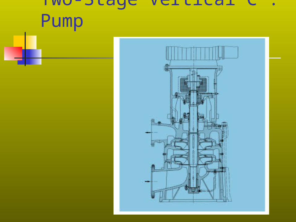
Two-Stage Vertical C : Pump
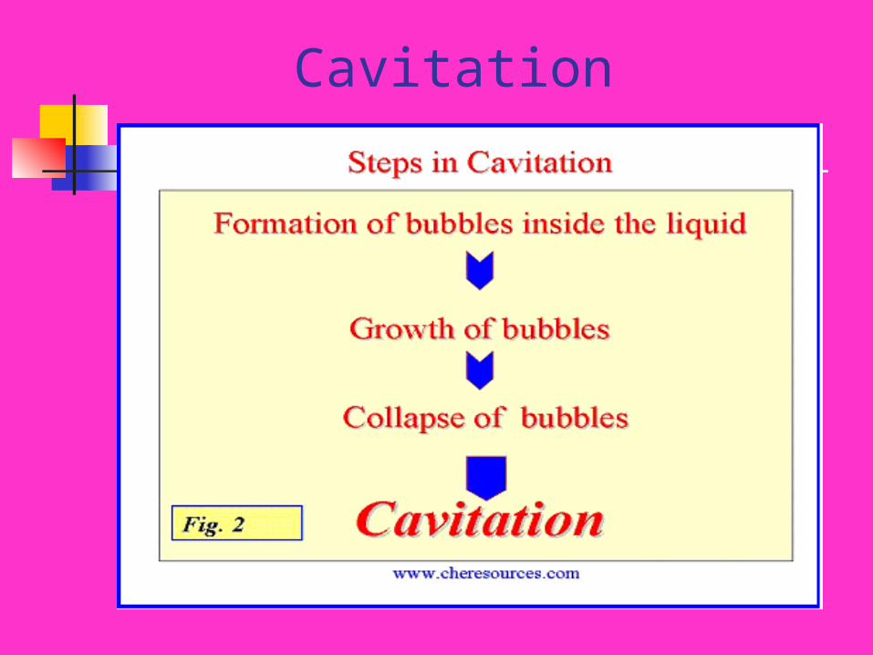
Cavitation
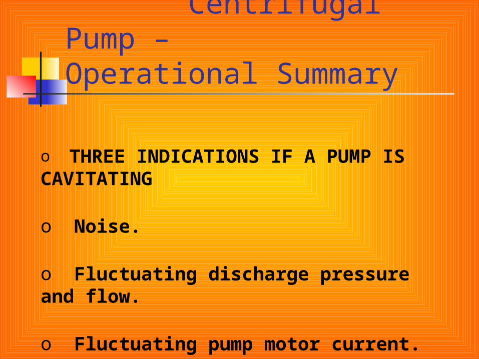
Centrifugal Pump – Operational Summary
o THREE INDICATIONS IF A PUMP IS CAVITATING
o Noise.
o Fluctuating discharge pressure and flow.
o Fluctuating pump motor current.
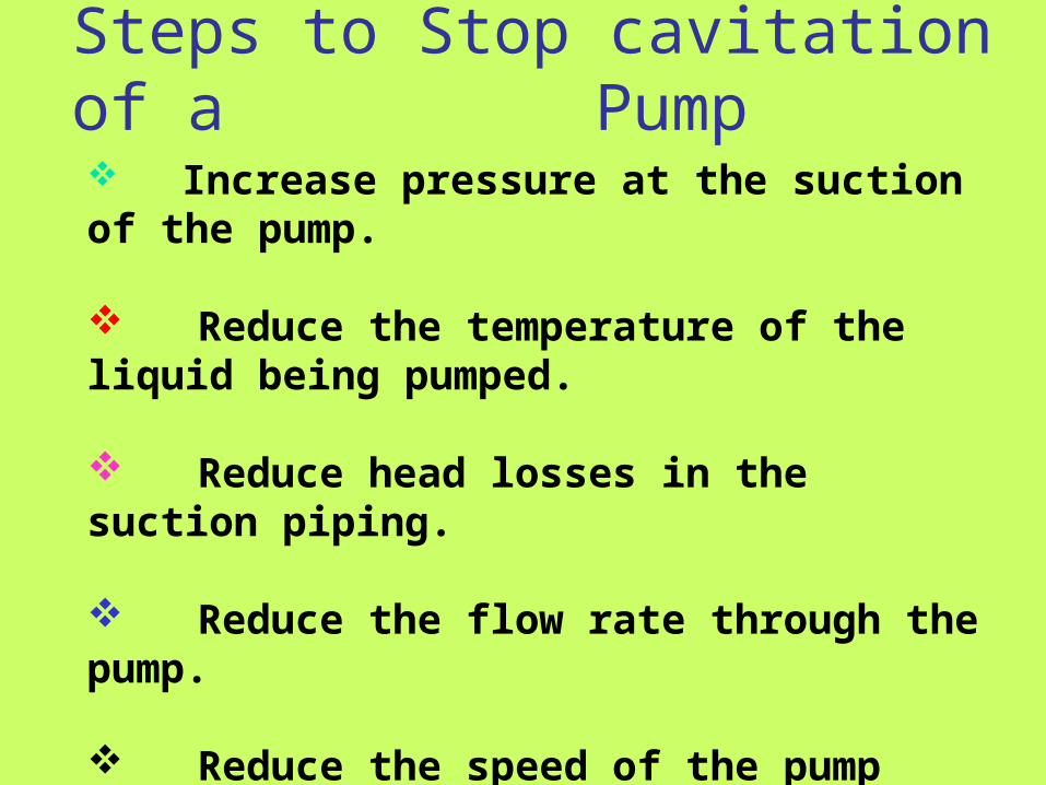
Steps to Stop cavitation of a Pump
Increase pressure at the suction of the pump.
Reduce the temperature of the liquid being pumped.
Reduce head losses in the suction piping.
Reduce the flow rate through the pump.
Reduce the speed of the pump impeller.
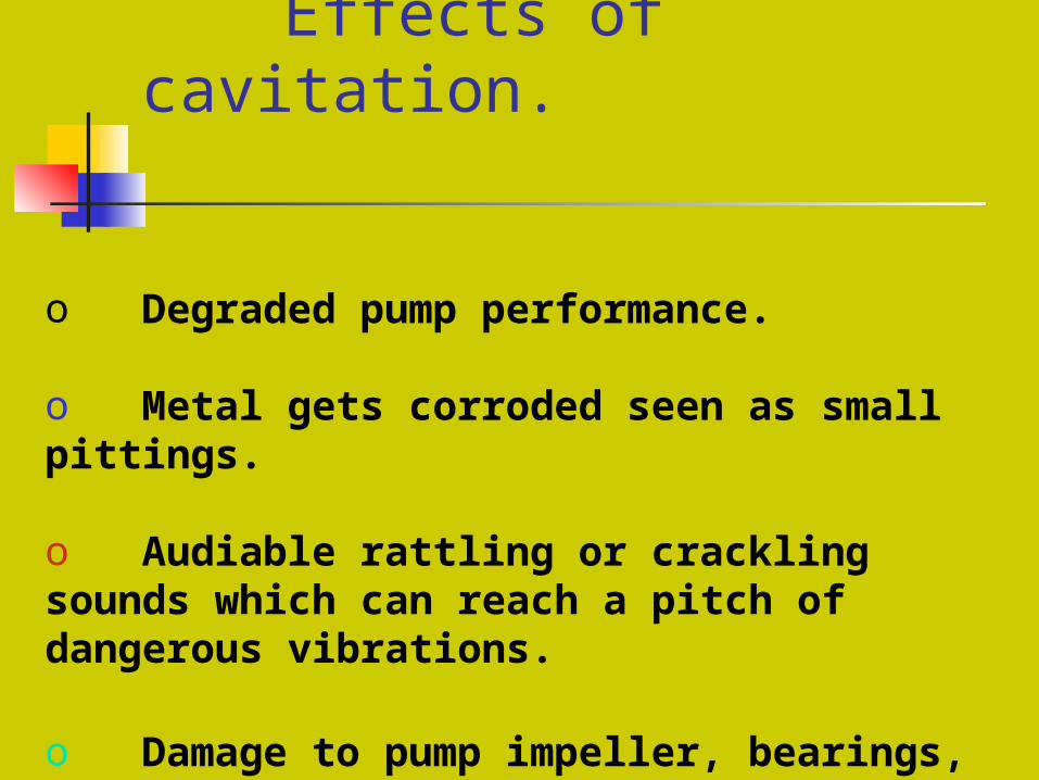
Effects of cavitation.
o Degraded pump performance.
o Metal gets corroded seen as small pittings.
o Audiable rattling or crackling sounds which can reach a pitch of dangerous vibrations.
o Damage to pump impeller, bearings, wear rings and seals.
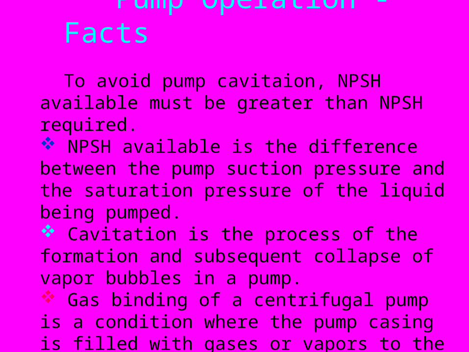
Pump Operation - Facts To avoid pump cavitaion, NPSH available must be greater than NPSH required. NPSH available is the difference between the pump suction pressure and the saturation pressure of the liquid being pumped. Cavitation is the process of the formation and subsequent collapse of vapor bubbles in a pump. Gas binding of a centrifugal pump is a condition where the pump casing is filled with gases or vapors to the point where the impeller is no longer able to contact enough fluid to function correctly.
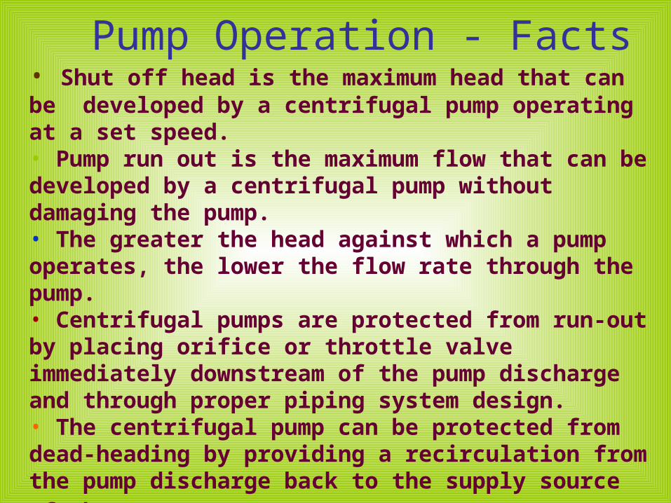
Pump Operation - Facts• Shut off head is the maximum head that can be developed by a centrifugal pump operating at a set speed.• Pump run out is the maximum flow that can be developed by a centrifugal pump without damaging the pump.• The greater the head against which a pump operates, the lower the flow rate through the pump.• Centrifugal pumps are protected from run-out by placing orifice or throttle valve immediately downstream of the pump discharge and through proper piping system design.• The centrifugal pump can be protected from dead-heading by providing a recirculation from the pump discharge back to the supply source of the pump.
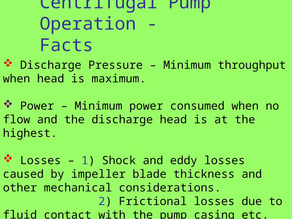
Centrifugal Pump Operation - Facts
Discharge Pressure – Minimum throughput when head is maximum.
Power – Minimum power consumed when no flow and the discharge head is at the highest.
Losses – 1) Shock and eddy losses caused by impeller blade thickness and other mechanical considerations. 2) Frictional losses due to fluid contact with the pump casing etc.3) Inlet and Impact losses.
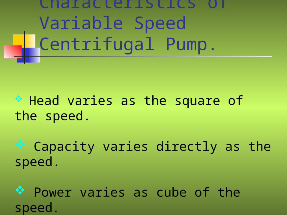
Characteristics of Variable Speed Centrifugal Pump.
Head varies as the square of the speed.
Capacity varies directly as the speed.
Power varies as cube of the speed.
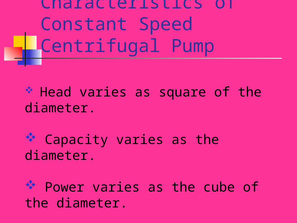
Characteristics of Constant Speed Centrifugal Pump
Head varies as square of the diameter.
Capacity varies as the diameter.
Power varies as the cube of the diameter.
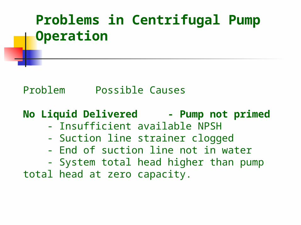
Problems in Centrifugal Pump Operation
Problem Possible Causes No Liquid Delivered - Pump not primed - Insufficient available NPSH - Suction line strainer clogged - End of suction line not in water - System total head higher than pump total head at zero capacity.
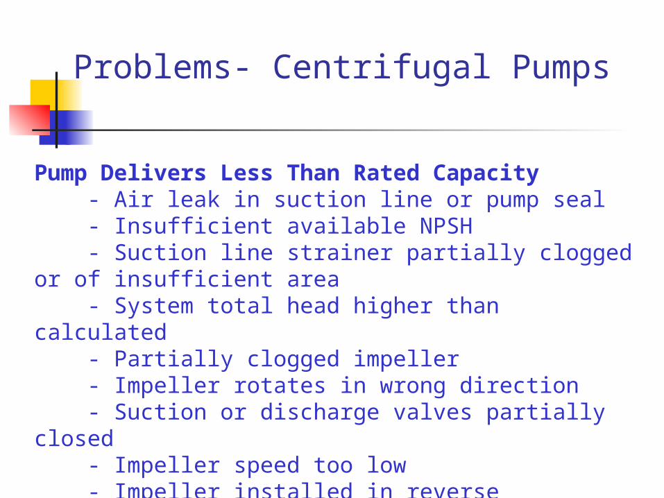
Problems- Centrifugal Pumps
Pump Delivers Less Than Rated Capacity - Air leak in suction line or pump seal - Insufficient available NPSH - Suction line strainer partially clogged or of insufficient area - System total head higher than calculated - Partially clogged impeller - Impeller rotates in wrong direction - Suction or discharge valves partially closed - Impeller speed too low - Impeller installed in reverse direction.
Problems- Centrifugal Pumps
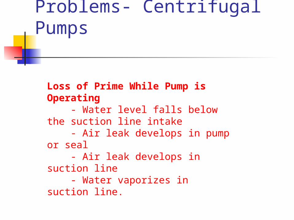
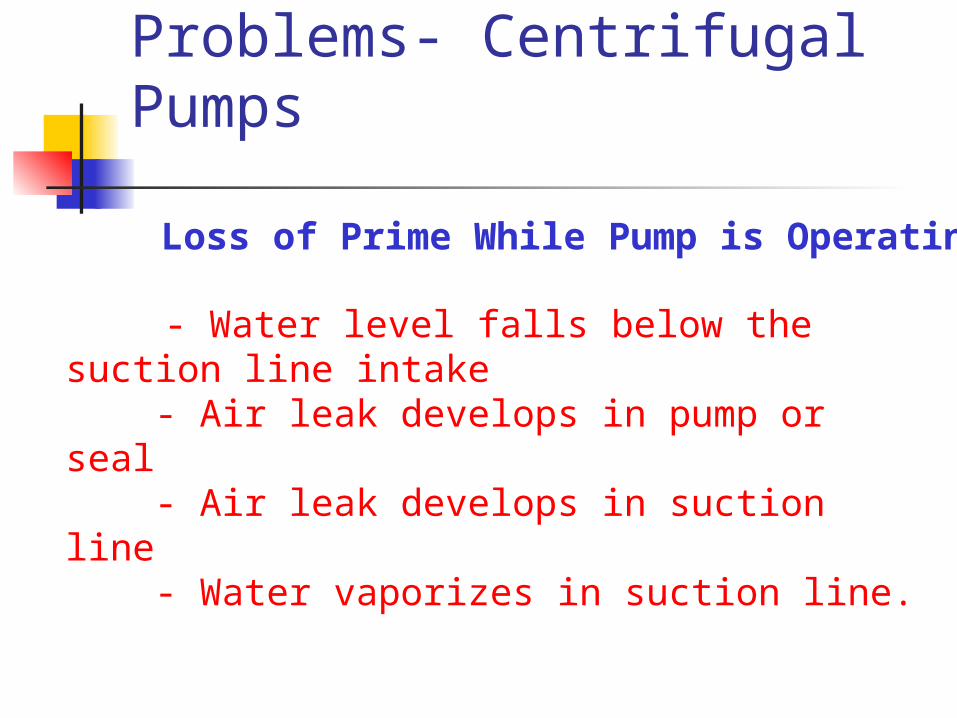
Loss of Prime While Pump is Operating - Water level falls below the suction line intake - Air leak develops in pump or seal - Air leak develops in suction line - Water vaporizes in suction line.
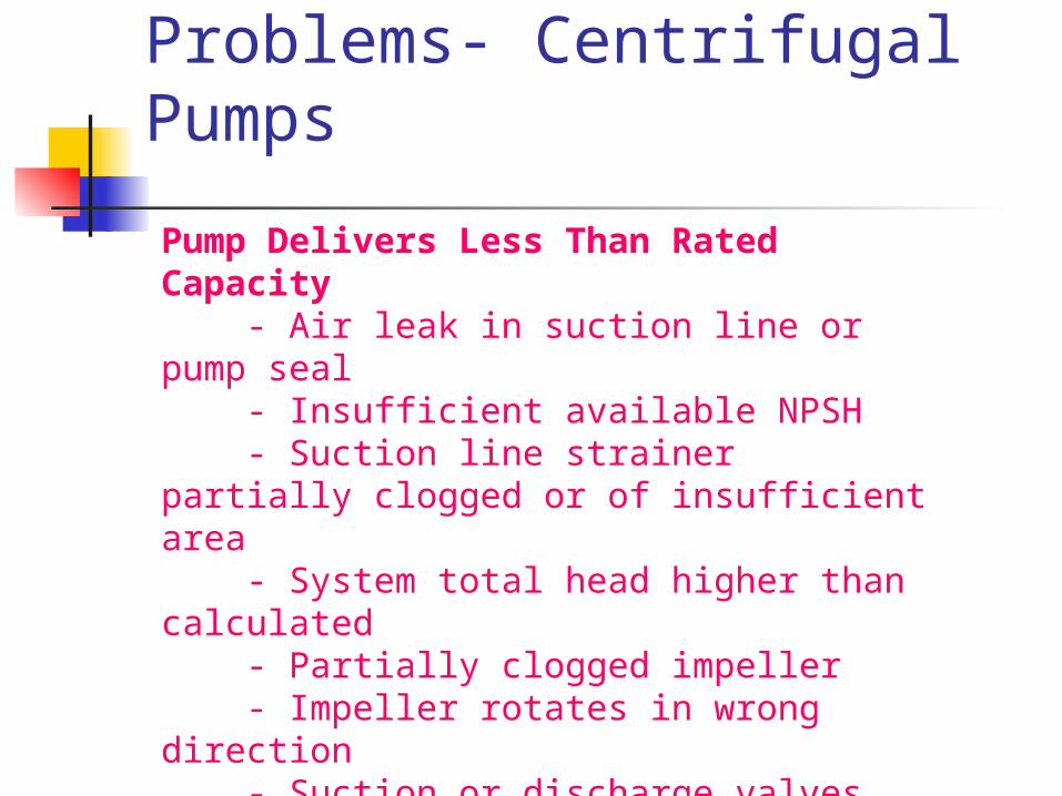
Pump Delivers Less Than Rated Capacity - Air leak in suction line or pump seal - Insufficient available NPSH - Suction line strainer partially clogged or of insufficient area - System total head higher than calculated - Partially clogged impeller - Impeller rotates in wrong direction - Suction or discharge valves partially closed - Impeller speed too low - Impeller installed in reverse direction.
Problems- Centrifugal Pumps
Problems- Centrifugal Pumps
Loss of Prime While Pump is Operating
- Water level falls below the suction line intake - Air leak develops in pump or seal - Air leak develops in suction line - Water vaporizes in suction line.
Problems- Centrifugal Pumps
Pump Takes Too Much Power - Impeller speed too high
- Shaft packing too light - Misalignment - Impeller touching casing - System total head too low causing the pump to deliver too much liquid - Impeller rotates - Impeller installed in wrong direction.
Problems- Centrifugal Pumps
Pump is Noisy - Cavitation - Misalignment - Foreign material inside pump - Bent shaft - Impeller touching casing.

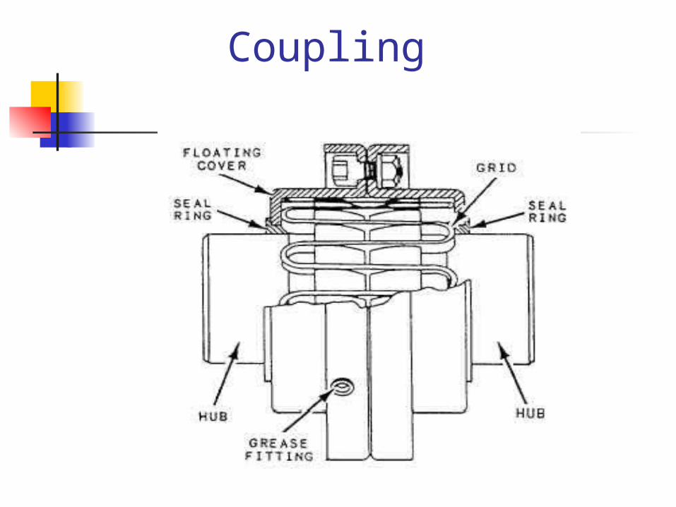
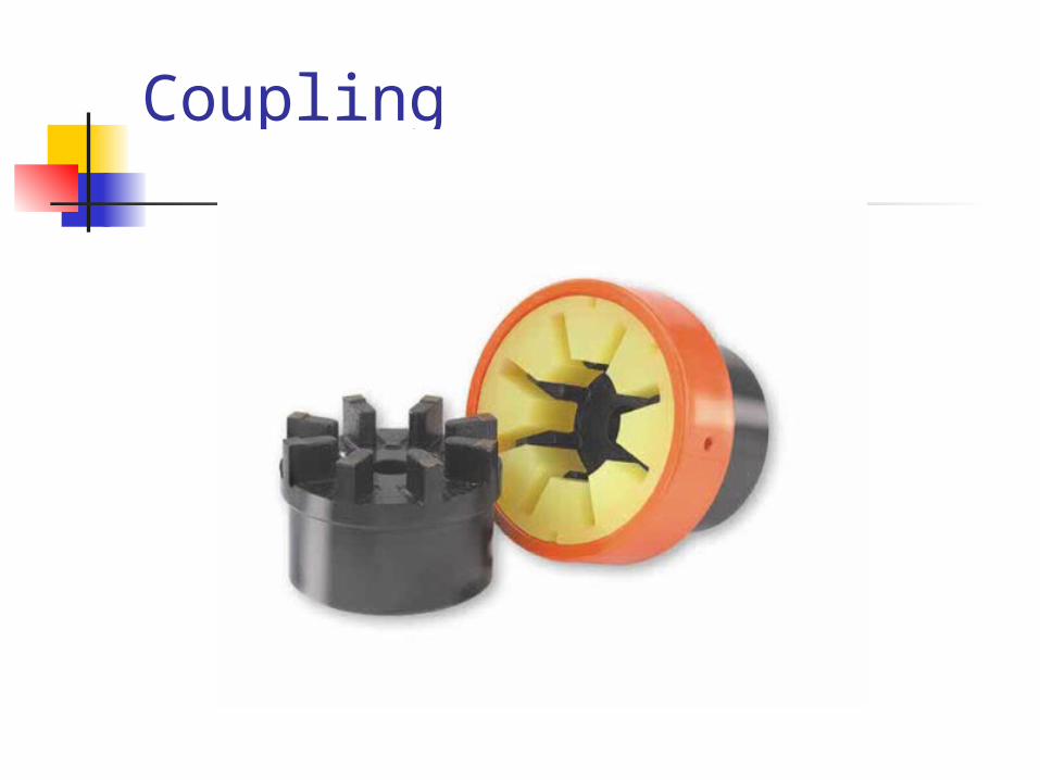
Coupling
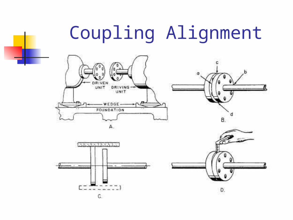
Coupling Alignment
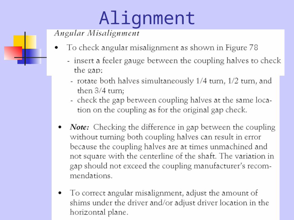
Alignment
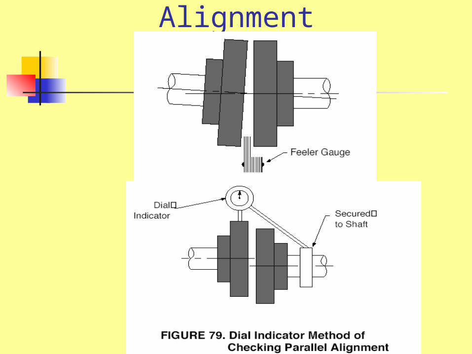
Alignment

Alignment
Centrifugal P/P, O’hauling
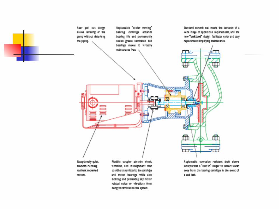
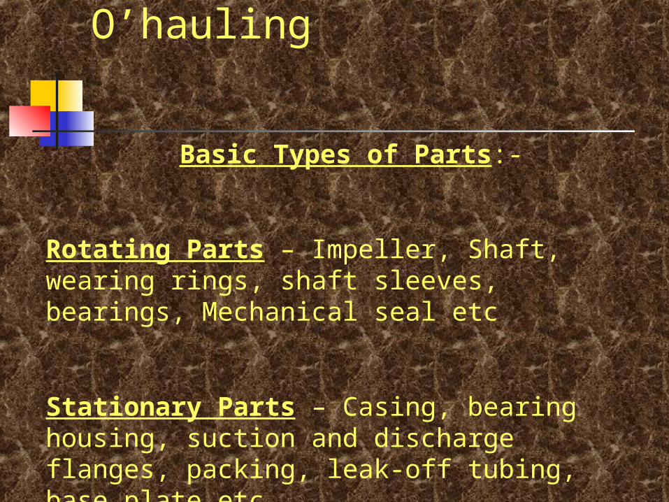
Basic Types of Parts:-
Rotating Parts – Impeller, Shaft, wearing rings, shaft sleeves, bearings, Mechanical seal etc
Stationary Parts – Casing, bearing housing, suction and discharge flanges, packing, leak-off tubing, base plate etc
Cent: P/P, O’hauling- Impeller
Inspect eyes, vanes, shrouds,wearing rings, passages, hubs and other parts.
Corrosion, Cavitation, and Erosion are generally accompanied by a wasting away of the impeller and vane surfaces. Where attack is severe, the thinned sections may have holes through them or may warp and deflect.
Badly worn or corroded impellers may vibrate excessively. Balancing is required. Check on a lathe. Metal to be removed on heavier side. If required take a cut on the shroud, deepest at the rim.
Compare with a spare Impeller.
Cent: P/P, O’hauling- shaft Check for bent shaft; out of square, dirty or burred impeller end of the shaft or spacer sleeve. Check – Lock nut washer is burred or the faces of it and other parts are not parallel. Check for bent shaft by means of a dial gauge, swinging between lathe or other centers. Tap and check impeller shaft key to see it is tight. Twist of shaft under load, Expansion or corrosion will progressively loosen the impeller..
Cent:P/P O’hauling- wear ring
Wear rings are installed in the casing or impeller or both. It will run as bearings while lubricated by the fluid being pumped. Check the clearances to make sure it is within limits. If not replace the wear rings. Wear rings are usually made out of non-galling materials. EX:Bronze with dissimilar bronze. Make sure that the wear rings are fitted correctly.
Cent:P/P- O’hauling- Bearings
• Ball bearings etc. – Keep all rolling-contact bearings clean at all times. Use clean tools and clean surroundings. Use clean solvents and flushing oils. Clean inside of housing before replacing the bearings. Install new bearings as removed from their package, without washing. To remove a bearing, press or pull only on the rings which is tight press; pull straight. • Sleeve/Bush bearings – Check clearances, if over the limit value, replace the same.
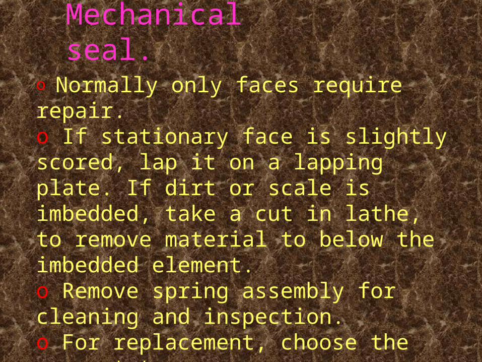
Cent:P/P,O’hauling-Mechanical seal.
o Normally only faces require repair.o If stationary face is slightly scored, lap it on a lapping plate. If dirt or scale is imbedded, take a cut in lathe, to remove material to below the imbedded element.o Remove spring assembly for cleaning and inspection.o For replacement, choose the correct type.o Good Practice – To rotate pumps equipped with mechanical seals, once a day, when stopped.
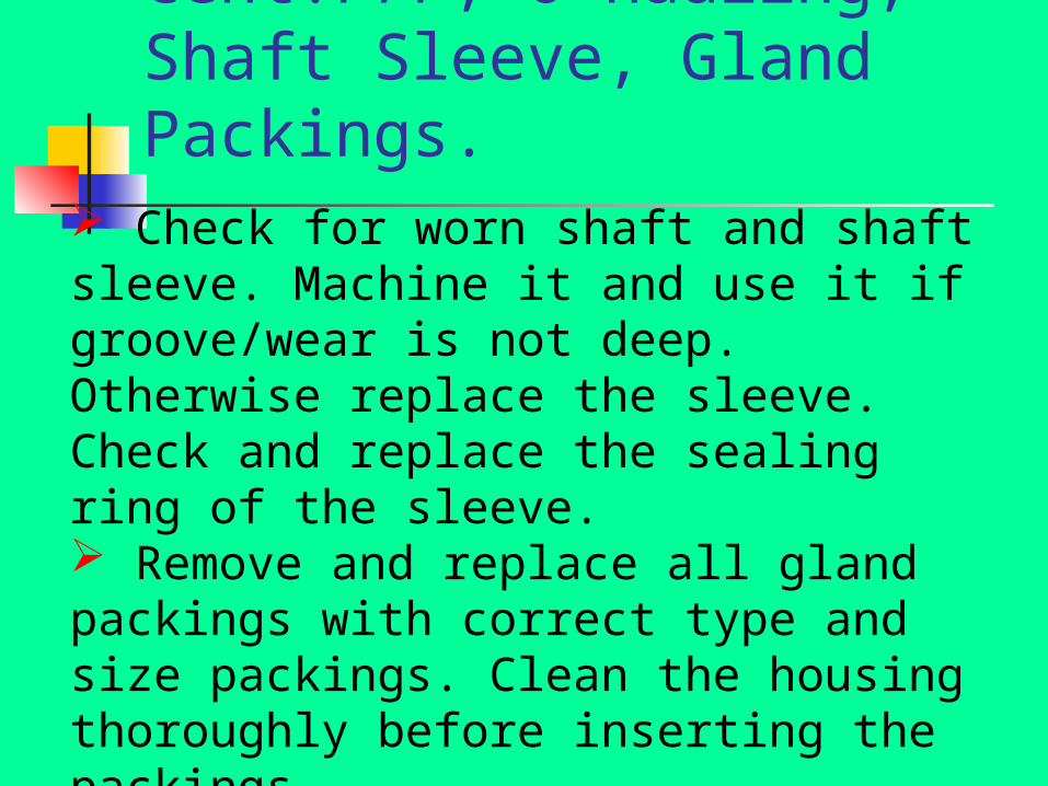
Cent:P/P, O’hauling, Shaft Sleeve, Gland Packings.
Check for worn shaft and shaft sleeve. Machine it and use it if groove/wear is not deep. Otherwise replace the sleeve. Check and replace the sealing ring of the sleeve. Remove and replace all gland packings with correct type and size packings. Clean the housing thoroughly before inserting the packings. Do not over-tight the gland. Check by rotating the shaft by hand.
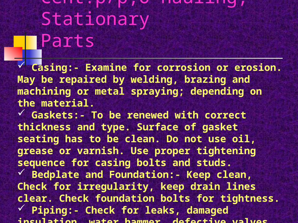
Cent:p/p,O’hauling, Stationary Parts
Casing:- Examine for corrosion or erosion. May be repaired by welding, brazing and machining or metal spraying; depending on the material. Gaskets:- To be renewed with correct thickness and type. Surface of gasket seating has to be clean. Do not use oil, grease or varnish. Use proper tightening sequence for casing bolts and studs. Bedplate and Foundation:- Keep clean, Check for irregularity, keep drain lines clear. Check foundation bolts for tightness. Piping:- Check for leaks, damaged insulation, water hammer, defective valves, improper alignment etc.

Axial Pump
Axial Pump
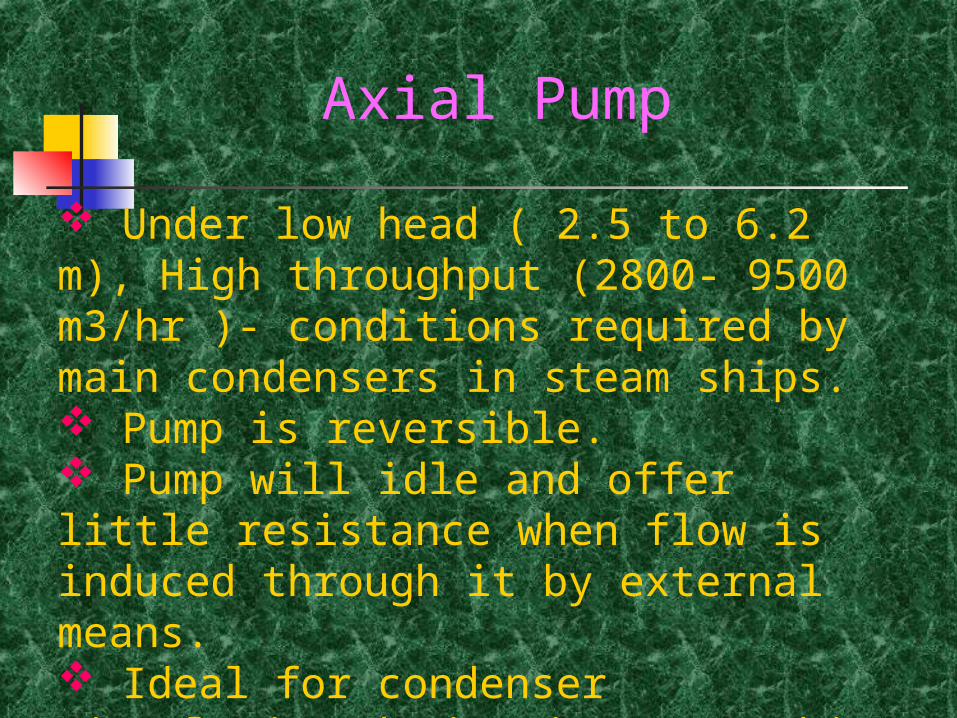
Under low head ( 2.5 to 6.2 m), High throughput (2800- 9500 m3/hr )- conditions required by main condensers in steam ships. Pump is reversible. Pump will idle and offer little resistance when flow is induced through it by external means. Ideal for condenser circulating duties in steam ships and for heeling and trimming duties.
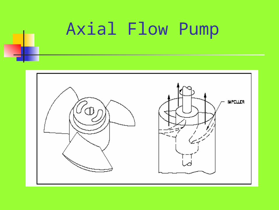
Axial Flow Pump A screw propeller by causing and axial acceleration of liquid within its blades, create a pressure increase. Incidental rotation imparted to the liquid is converted to axial movement by suitably shaped outlet guide vanes. Throttling of the discharge valve causes a rise in pressure and power. With discharge valve closed and zero discharge, the head will be three times and power doubled. Causes water hammer.
Axial Flow Pump
Mixed Flow Pump
Positive Displacement Pumps.
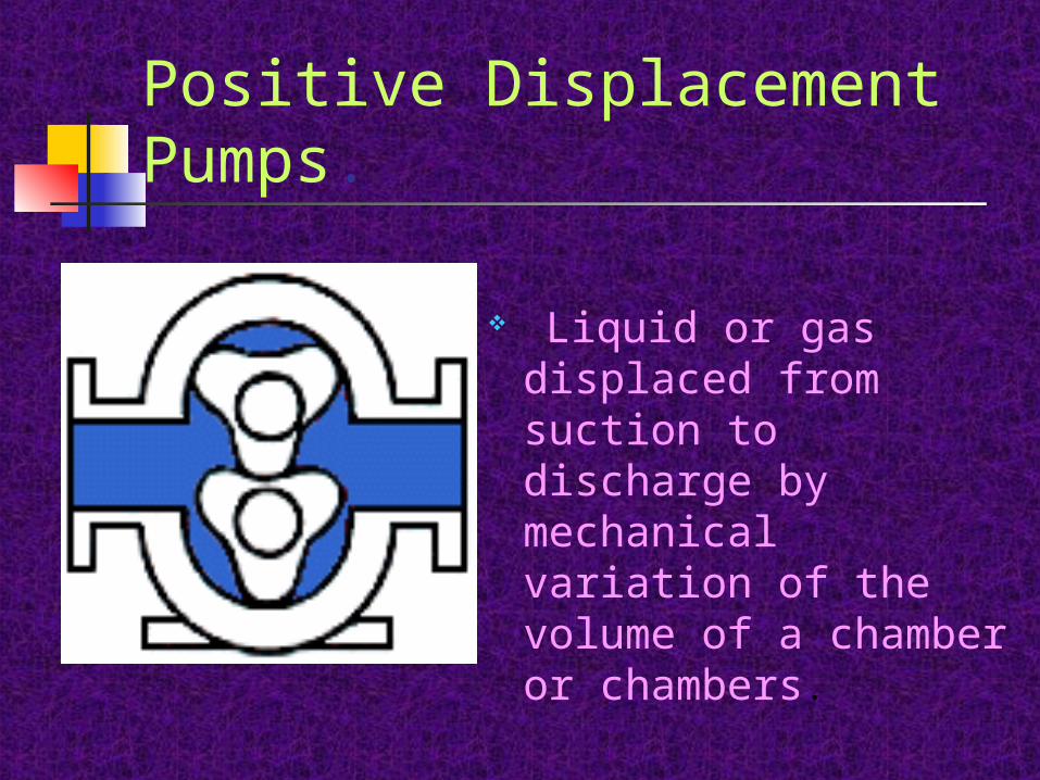
Liquid or gas displaced from suction to discharge by mechanical variation of the volume of a chamber or chambers.
centrifugalpumps11.gif
centrifugalpumps11.gif
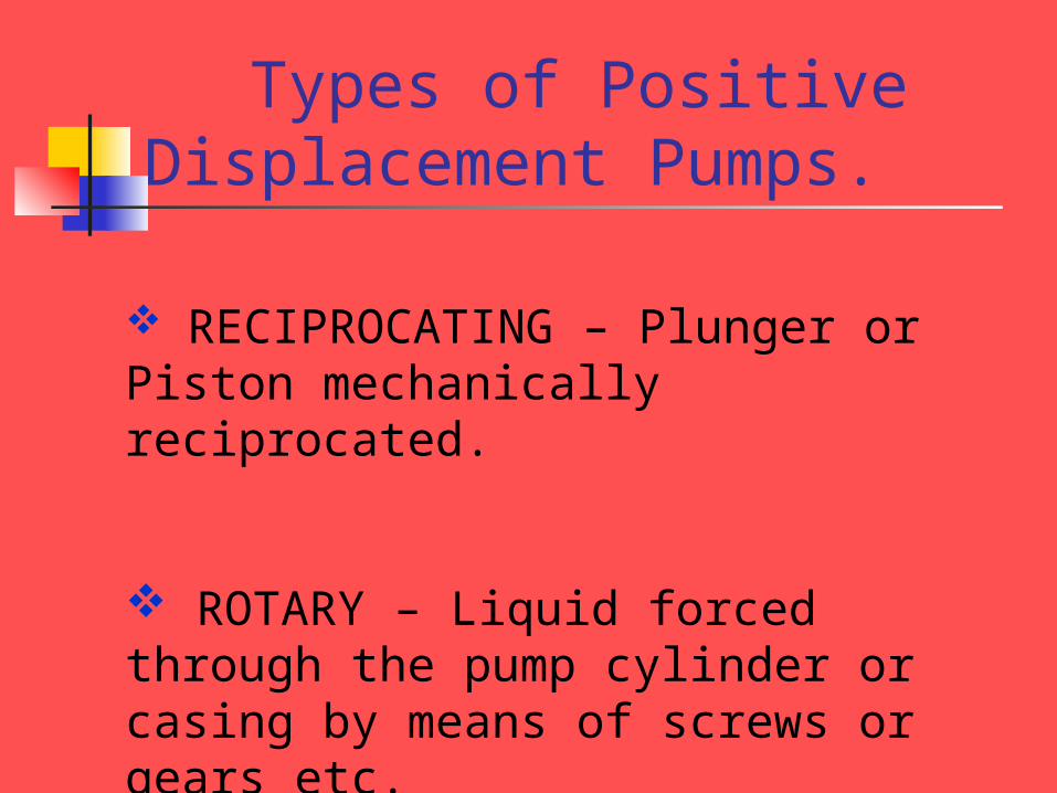
Types of Positive Displacement Pumps.
RECIPROCATING – Plunger or Piston mechanically reciprocated.
ROTARY – Liquid forced through the pump cylinder or casing by means of screws or gears etc.
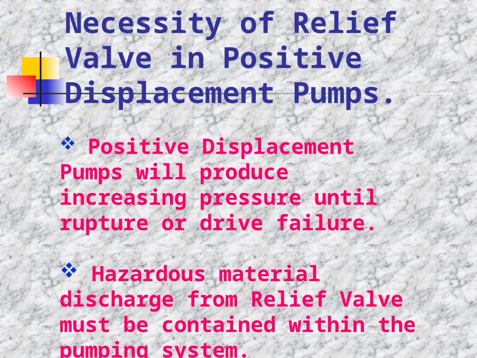
Necessity of Relief Valve in Positive Displacement Pumps.
Positive Displacement Pumps will produce increasing pressure until rupture or drive failure.
Hazardous material discharge from Relief Valve must be contained within the pumping system.
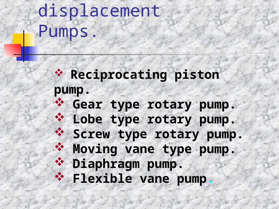
Types of Positive displacement Pumps.
Reciprocating piston pump. Gear type rotary pump. Lobe type rotary pump. Screw type rotary pump. Moving vane type pump. Diaphragm pump. Flexible vane pump.
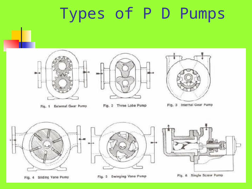
Types of P D Pumps
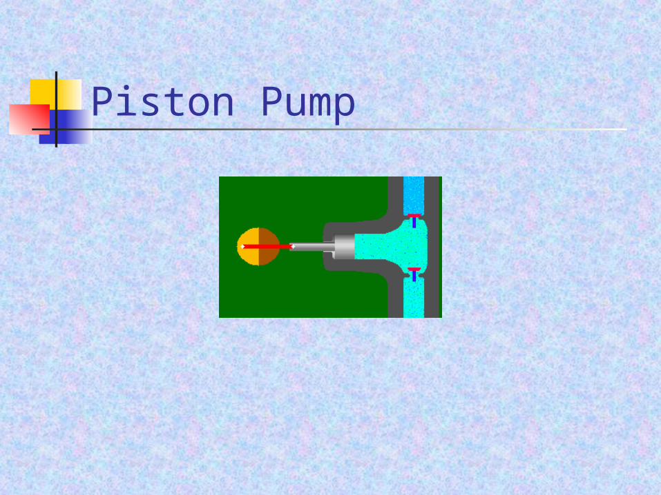
Piston Pump
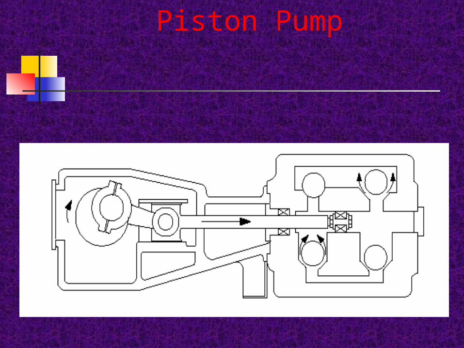
Piston Pump
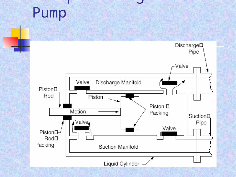
Reciprocating Piston Pump
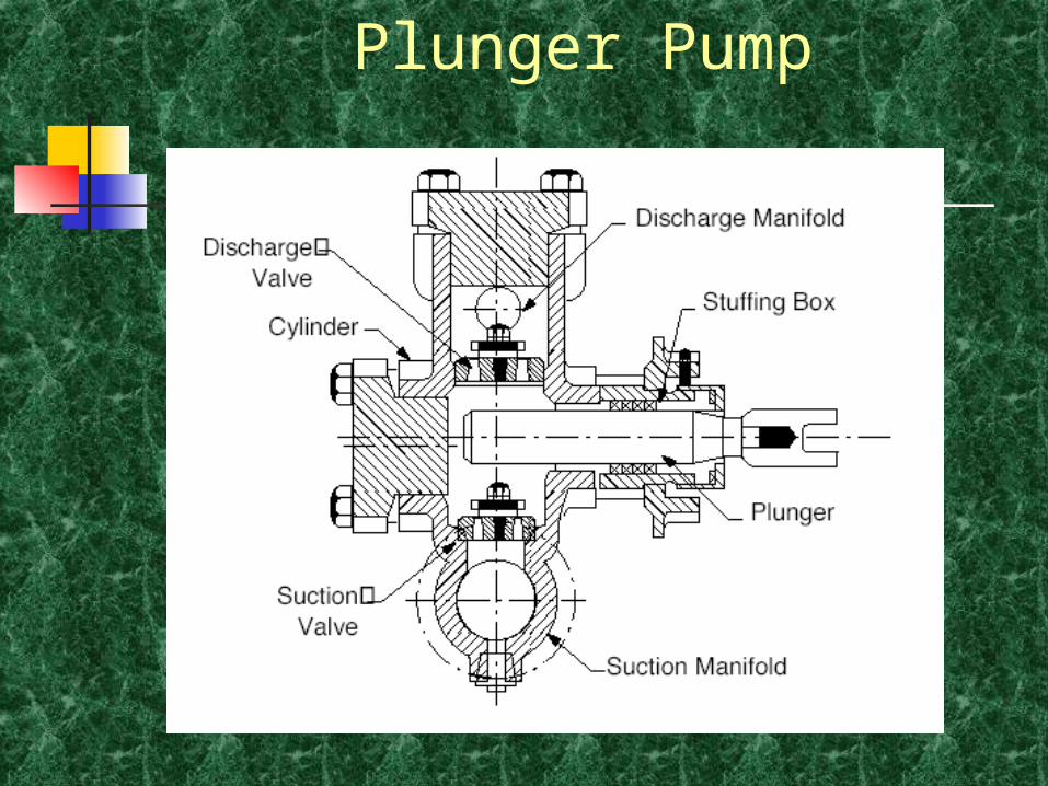
Plunger Pump
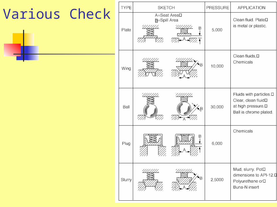
Various Check V/Vs
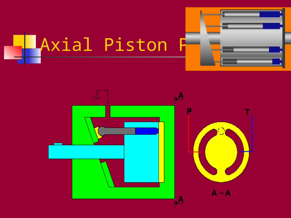
Axial Piston Pump
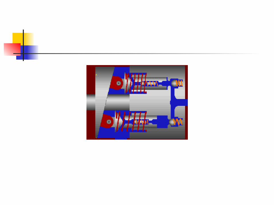
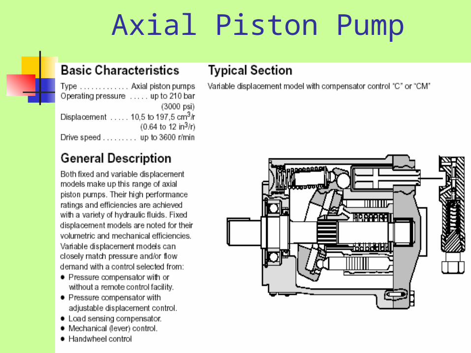
Axial Piston Pump
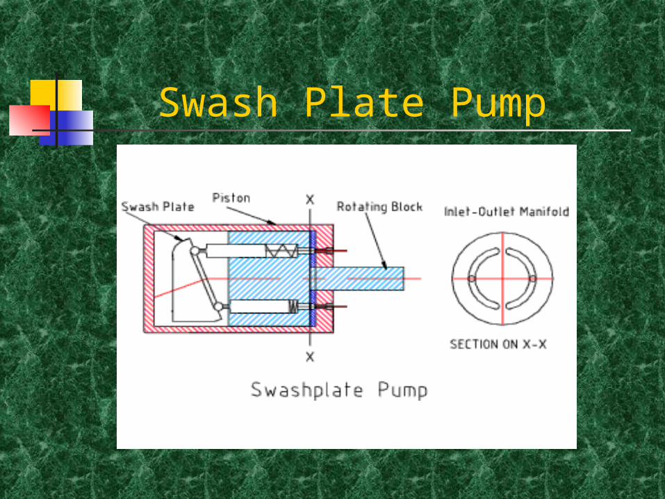
Swash Plate Pump
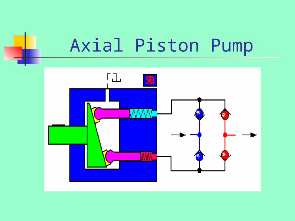
Axial Piston Pump
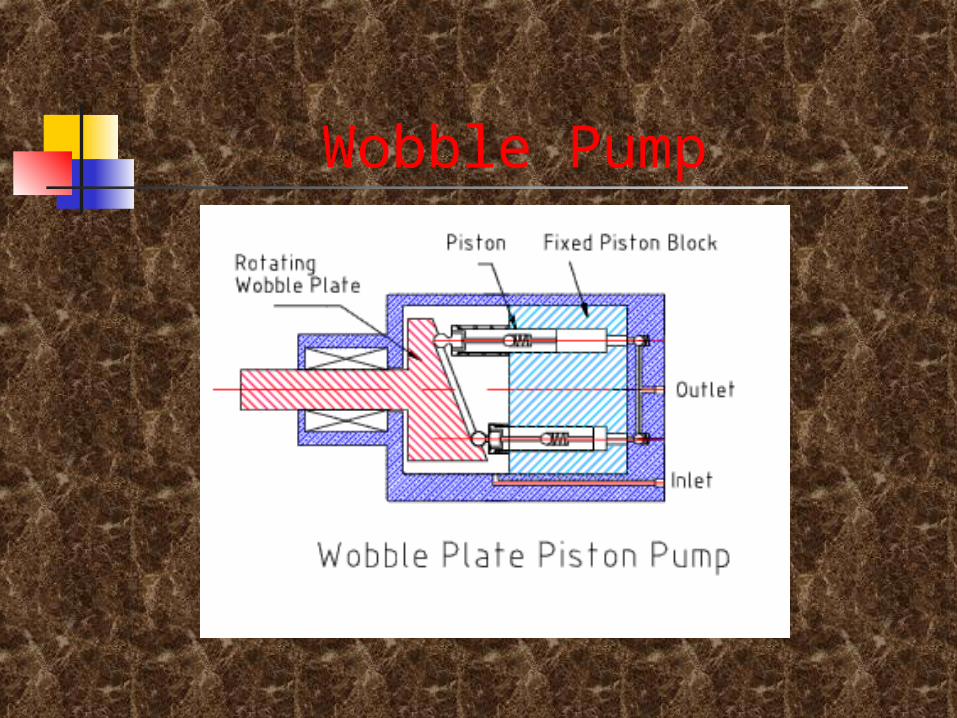
Wobble Pump
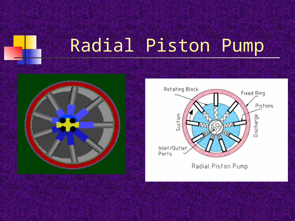
Radial Piston Pump
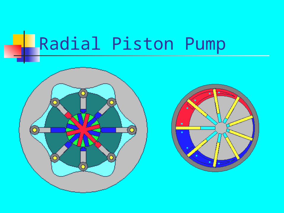
Radial Piston Pump
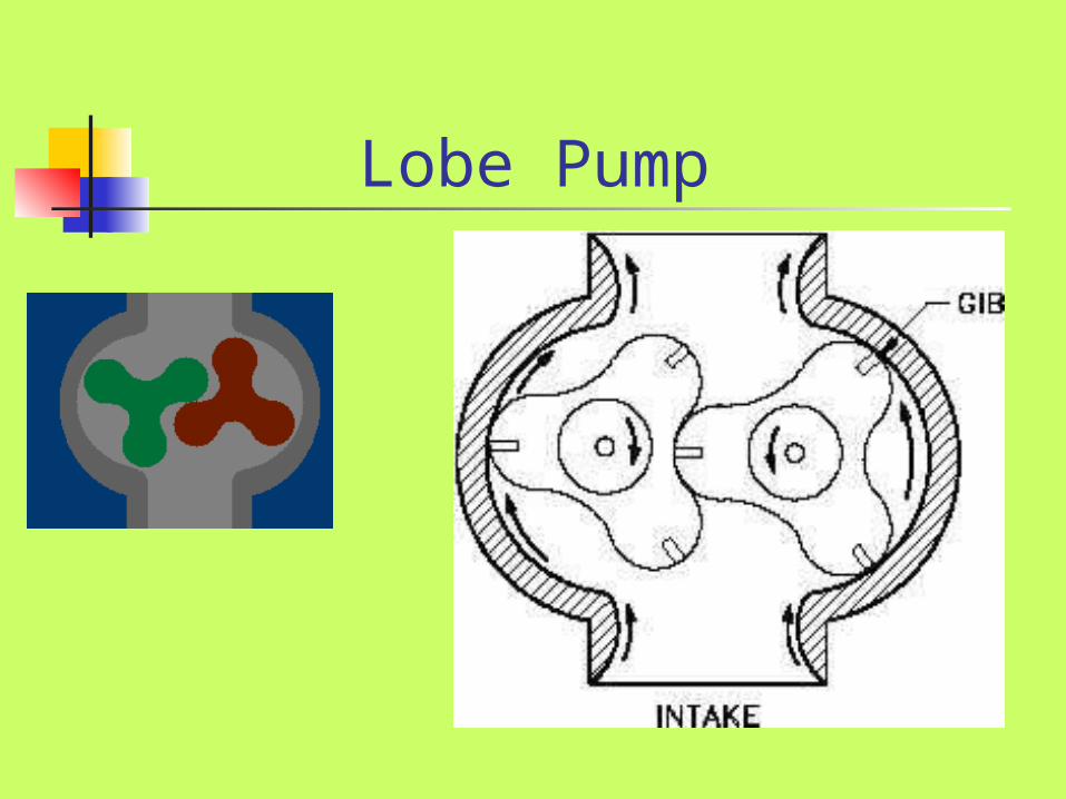
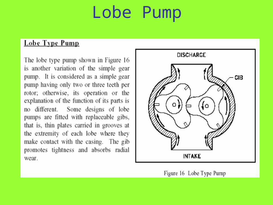
Lobe Pump
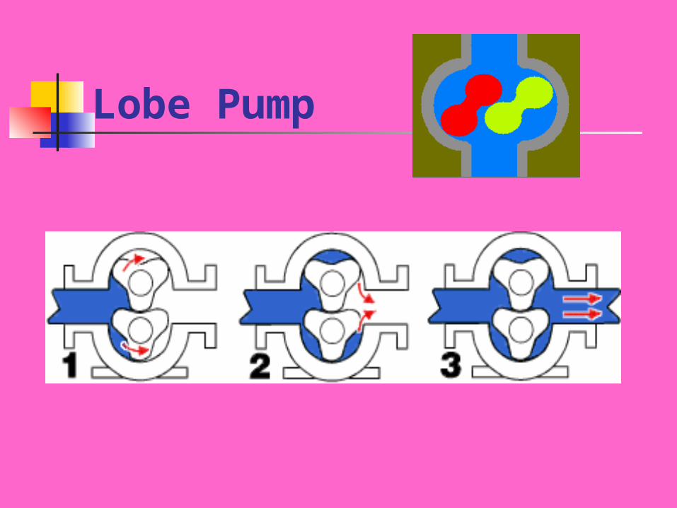
Lobe Pump
Lobe Pump
Two or more rotors cut with two, three or more lobes on each rotor. Rotors are synchronized for positive rotation by external gears. Liquid delivered in a small number of large quantities. Hence flow is not as constant as from gear pumps.
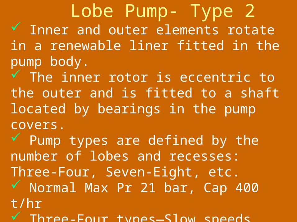
Lobe Pump- Type 2
Inner and outer elements rotate in a renewable liner fitted in the pump body. The inner rotor is eccentric to the outer and is fitted to a shaft located by bearings in the pump covers. Pump types are defined by the number of lobes and recesses: Three-Four, Seven-Eight, etc. Normal Max Pr 21 bar, Cap 400 t/hr Three-Four types—Slow speeds, high viscosity fluids Seven-Eight types—Higher speeds and lower viscosity fluids.
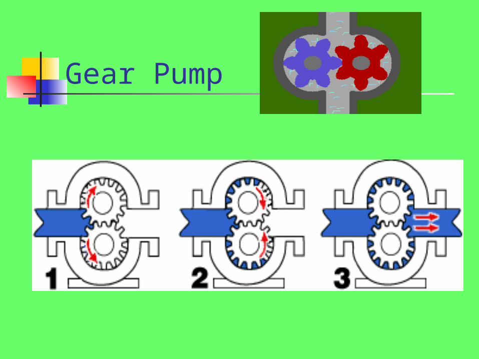
Gear Pump
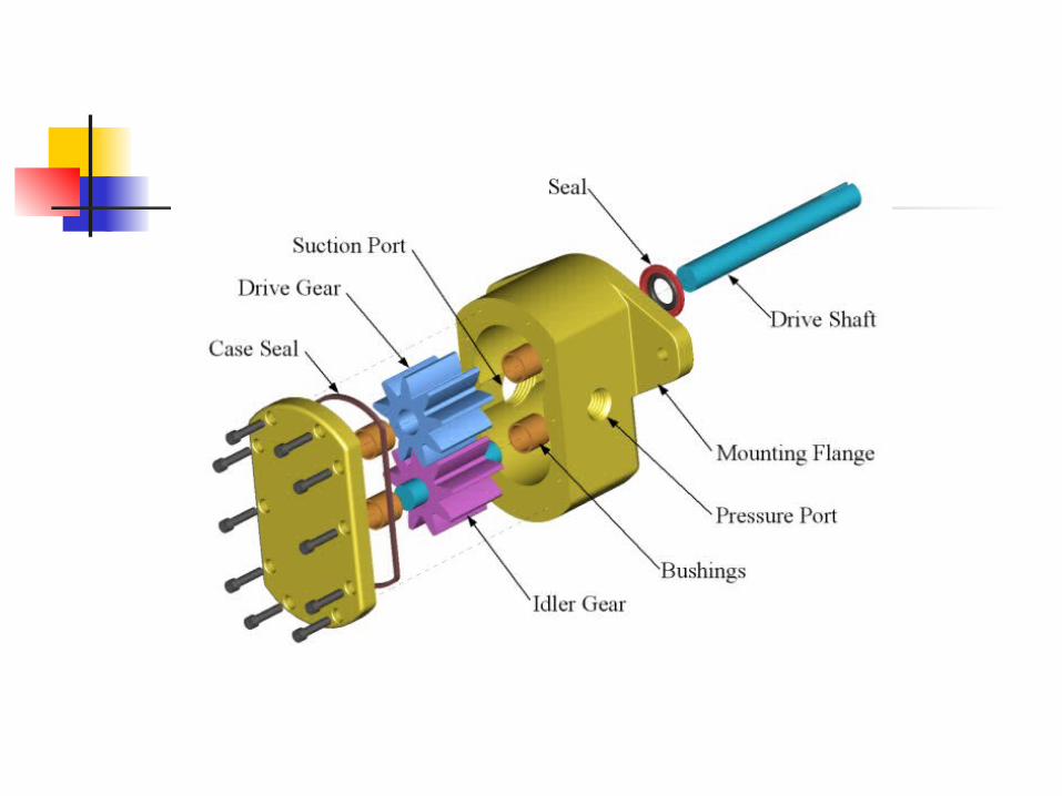
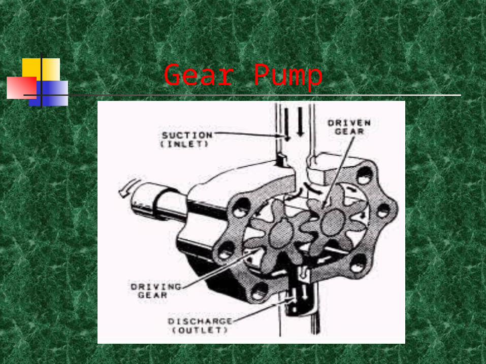
Gear Pump
Gear Pump
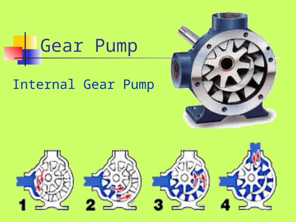
Internal Gear Pump
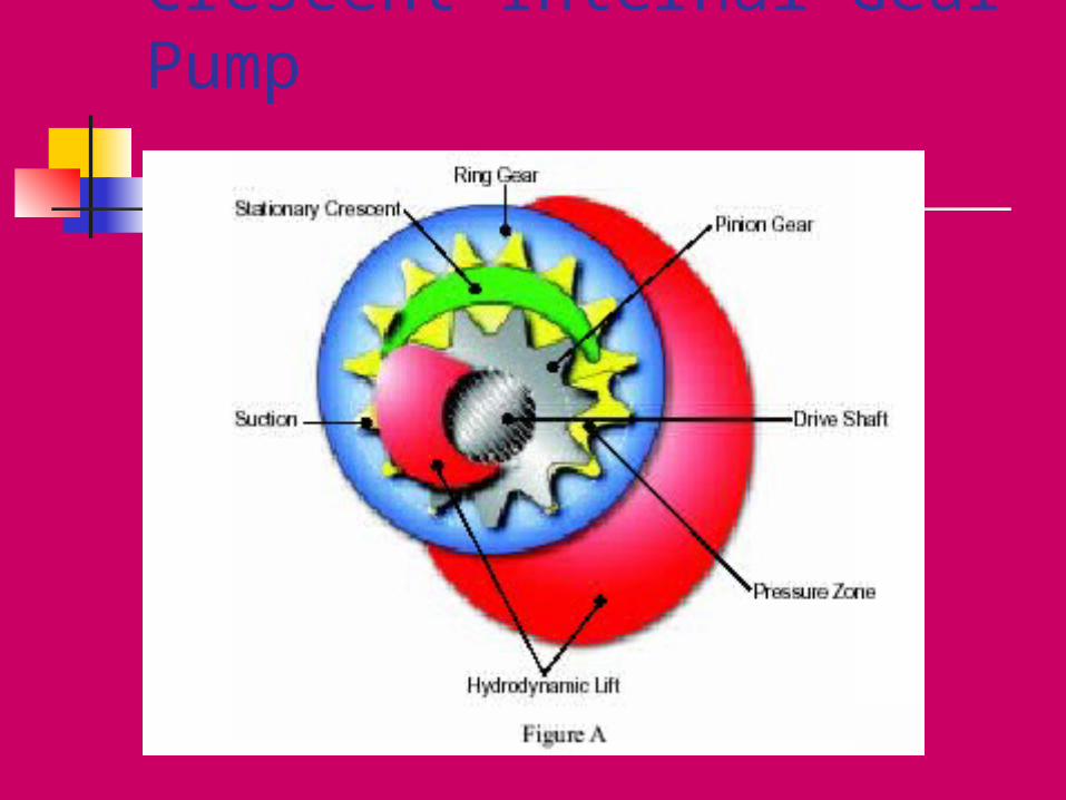
Crescent Internal Gear Pump
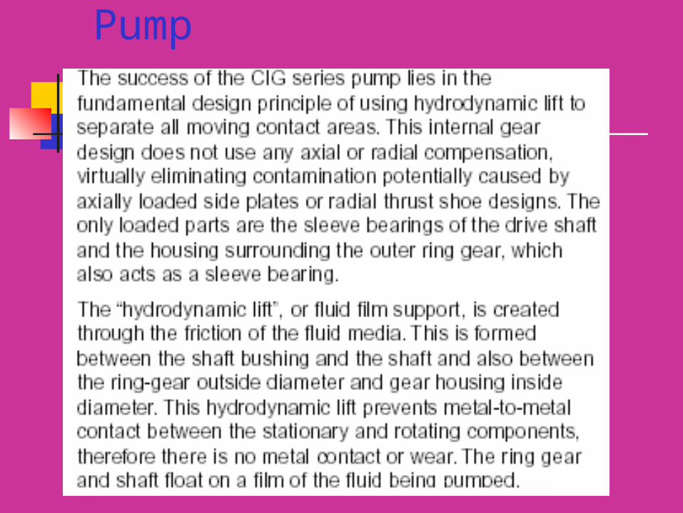
Crescent Internal Gear Pump

Classified by the type of gears used- Spur, Helical, Herringbone etc Commonly used on board for handling small quantities of Fuel oil, Lub oil etc Shafts running on bushes or bearings, usually lubricated by oil being pumped. Gear backlash,0.2-0.5mm (amount by which a tooth space exceeds the thickness of the engaging)- If no backlash, trapped oil between two teeth impedes gear rotation, Loss in power, additional load on bearings, spreading of gears and heating of the liquid.
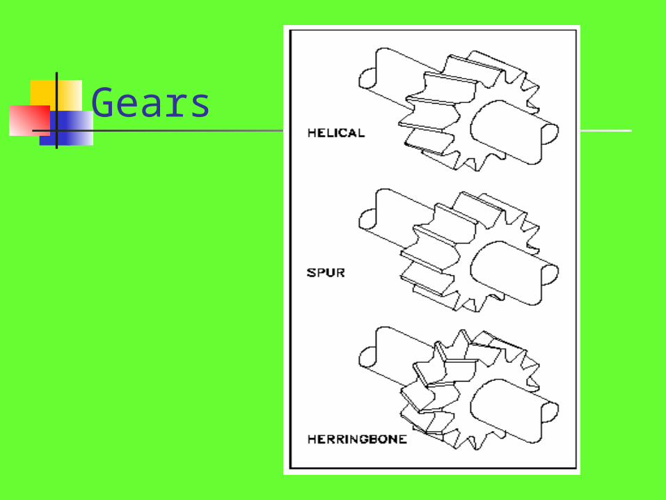
Gears
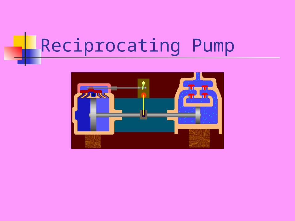
Reciprocating Pump
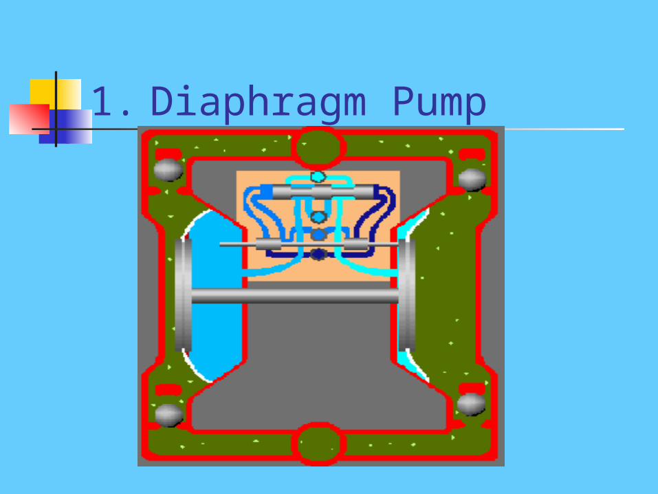
1. Diaphragm Pump
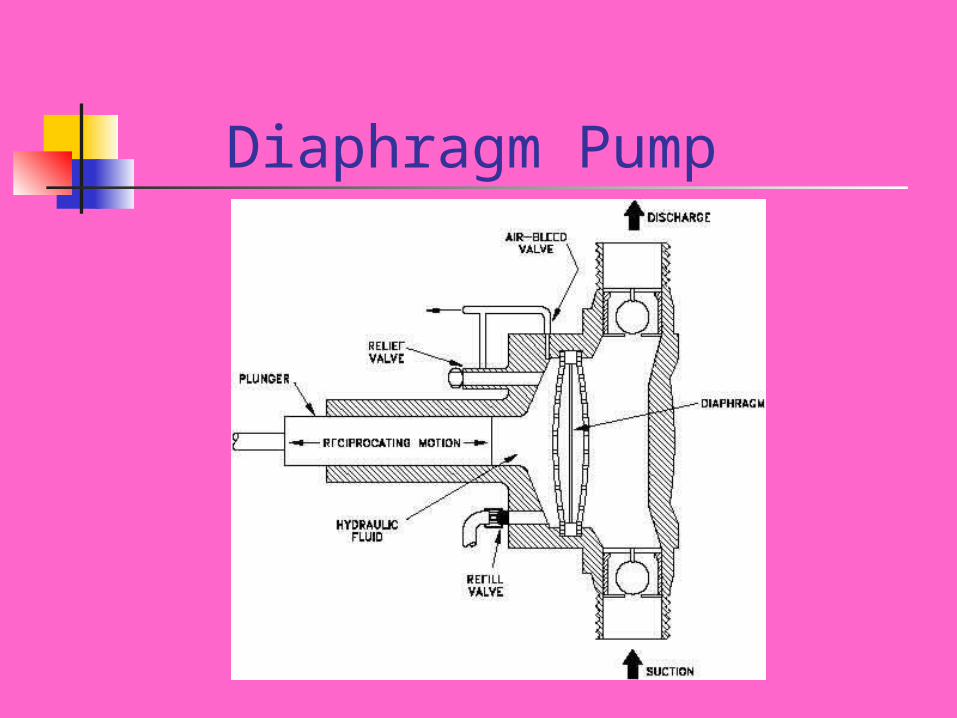
Diaphragm Pump
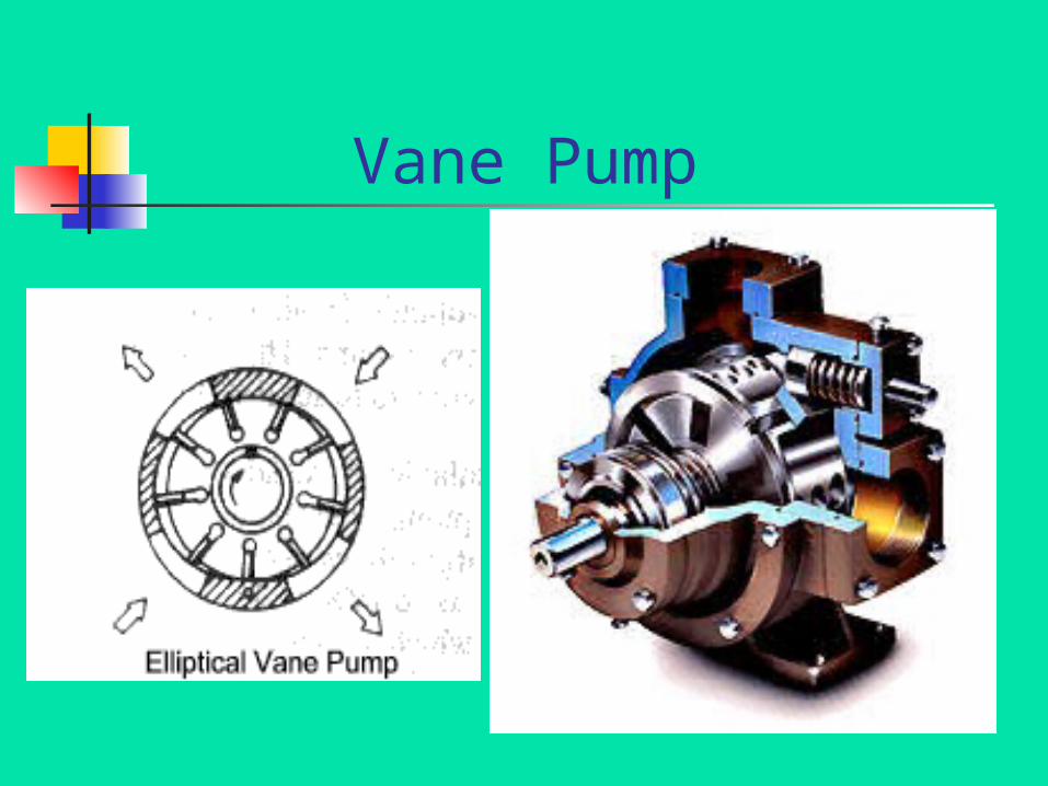
Vane Pump
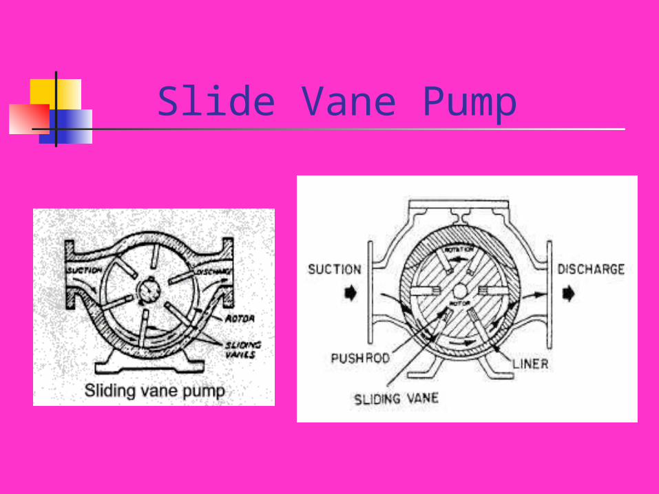
Slide Vane Pump
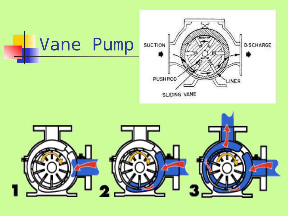
Vane Pump
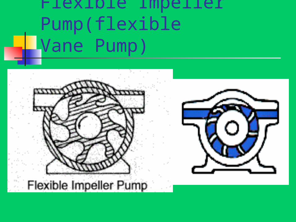
Flexible Impeller Pump(flexible Vane Pump)
Flexible Impeller Pump
o Self priming, can be mounted above or below the source of the fluid.o Simple construction- Inexpensive.o Gentle pumping action – effectively handles thin, viscous and particle-laden fluids.o Typical applications- Low rate, low pressure, high viscosity uses. Temperature range- 0 to 90 oC.o Impeller- Flexible synthetic rubber Housing- Stainless Steel
Lobe Pump
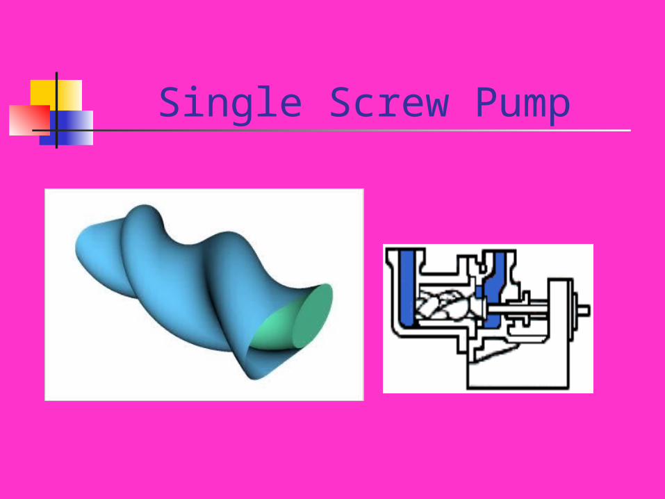
Single Screw Pump
Single Screw Pump (Eccentric Helical Rotor Pump, Snake P/P)
Used for smooth flow, low capacity applications. During rotation, rotor (stainless steel) tightens against the stator (natural or synthetic rubber) with double internal screw threads and enclosed fluid is displaced axially.All cross sections of rotor are circular.Center-line of pump moves radially during rotation, hence driven through universal joint.
Double Screw Pump
• Mounted horizontally or vertically.• Each screw shaft has a right and left hand screw which ensures hydraulic balance.• Metal contact avoided by timing gears.• Liquid drawn and pumped inwards to the discharge located at rotor mid-length. • Discharge is without pulsations.• For non-corrosive liquids of reasonable lubricity, usually internal bearings are used.
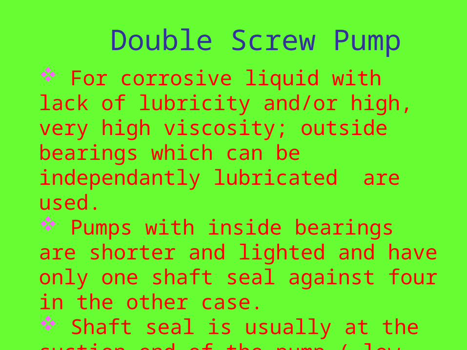
Double Screw Pump For corrosive liquid with lack of lubricity and/or high, very high viscosity; outside bearings which can be independantly lubricated are used. Pumps with inside bearings are shorter and lighted and have only one shaft seal against four in the other case. Shaft seal is usually at the suction end of the pump ( low pressure or vacuum ). Usually mechanical seals are cooled and lubricated by the pumped liquid.
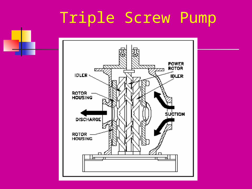
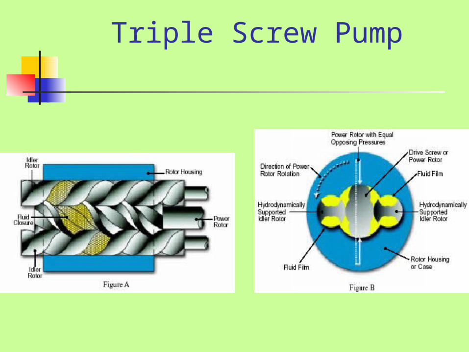
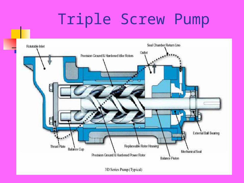
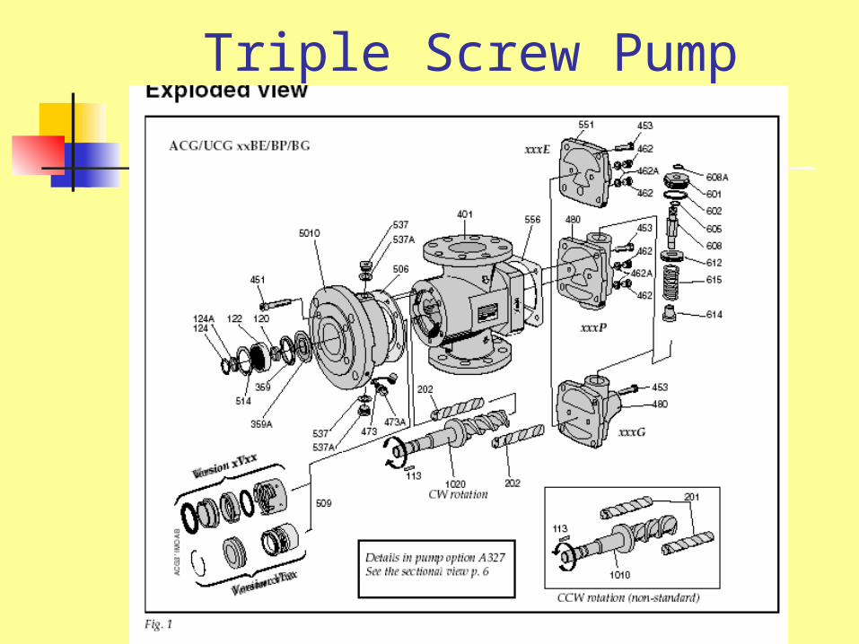
Triple Screw Pump
Triple Screw Pumps
Triple Screw Pump.
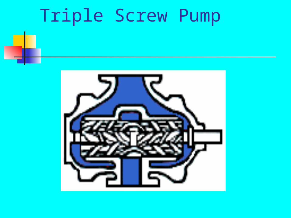
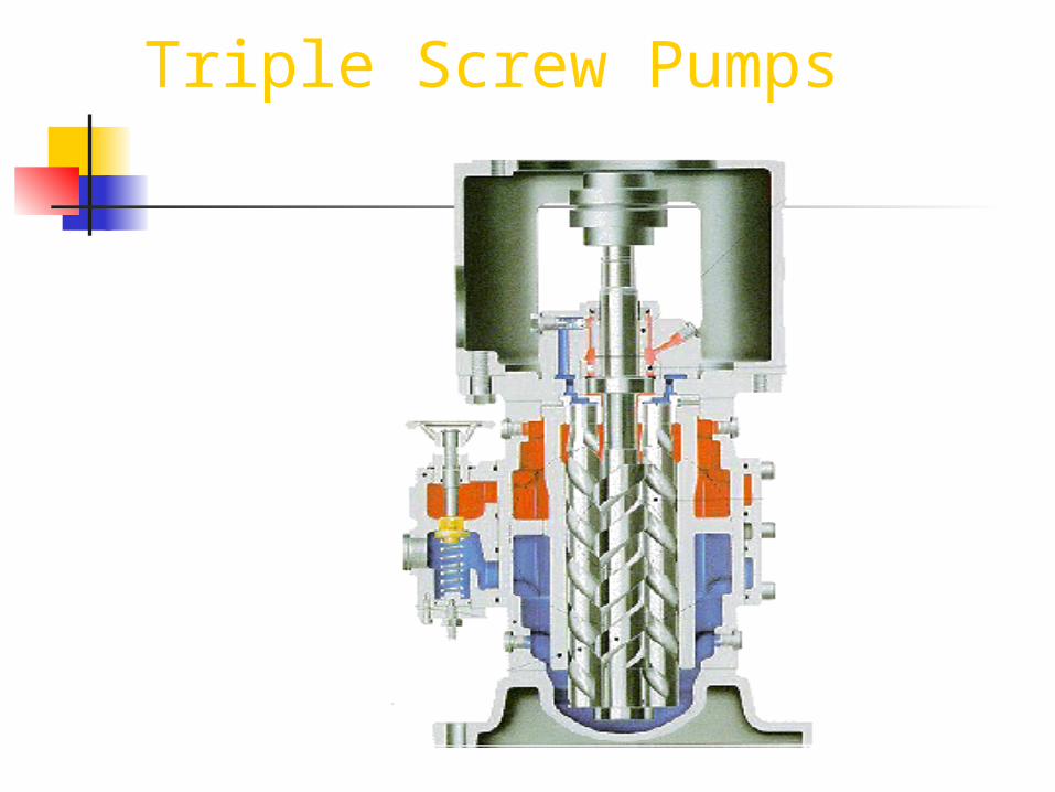
Center screw is driven, outer screws are idle. Outer screws are driven by fluid pressure and act as seals. When screws rotate, their close relation to each other creates pockets in the helices; these pockets move axially. These pumps work well at high pressure and with high viscosity fluids.
Triple Screw Pump
Triple Screw Pump
Triple Screw Pump
Triple Screw Pump
Screw Pumps
High helix angle screws are used for relatively high speed on small pumps.
Lower helix angle screws are used on large pumps.
Screw Pumps Are Used---
For pumping high viscosity liquids such as oils and some liquid cargoes. For draining tanks of high vapor pressure liquids, since self priming and being able to pump liquid and vapor without loss of suction. For operation at high rotational speeds, since it can be easily matched with standard motors.
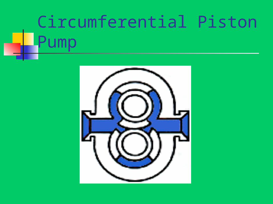
Circumferential Piston Pump
Positive Displacement Pumps
Often used for small capacities and when needed to avoid churning. Also used for high viscosity liquids. Can control flow by regulating speed. Used often for high or very high pressure. Also as metering pumps. Will produce any head that is impressed on them.
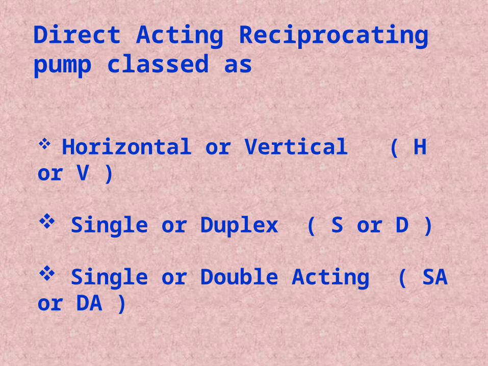
Direct Acting Reciprocating pump classed as
Horizontal or Vertical ( H or V )
Single or Duplex ( S or D )
Single or Double Acting ( SA or DA )
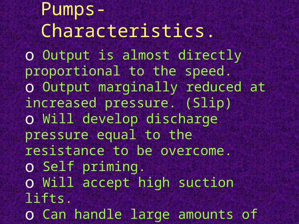
Positive Displacement Pumps- Characteristics.
o Output is almost directly proportional to the speed.o Output marginally reduced at increased pressure. (Slip)o Will develop discharge pressure equal to the resistance to be overcome.o Self priming.o Will accept high suction lifts.o Can handle large amounts of entrained gases or vapors.o Construction is complicated.
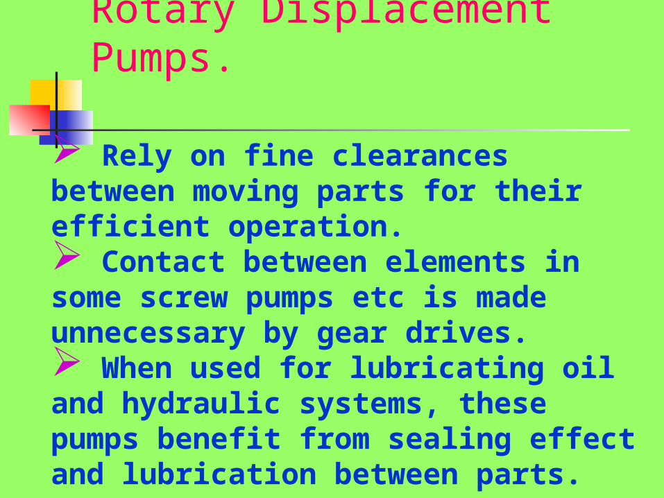
Rotary Displacement Pumps.
Rely on fine clearances between moving parts for their efficient operation. Contact between elements in some screw pumps etc is made unnecessary by gear drives. When used for lubricating oil and hydraulic systems, these pumps benefit from sealing effect and lubrication between parts.
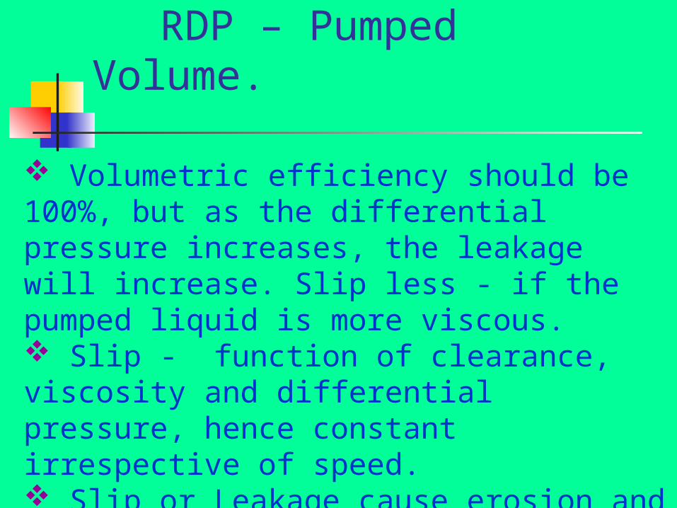
RDP – Pumped Volume.
Volumetric efficiency should be 100%, but as the differential pressure increases, the leakage will increase. Slip less - if the pumped liquid is more viscous. Slip - function of clearance, viscosity and differential pressure, hence constant irrespective of speed. Slip or Leakage cause erosion and increase of clearance (more if liquid contains abrasives)
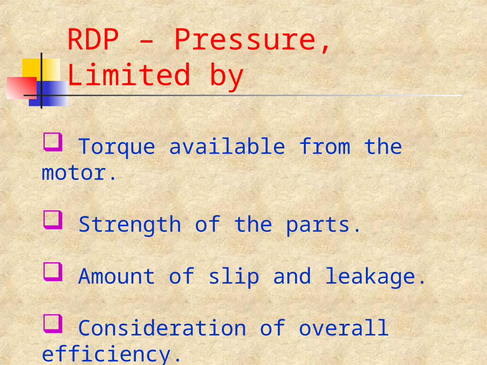
RDP – Pressure, Limited by
Torque available from the motor.
Strength of the parts.
Amount of slip and leakage.
Consideration of overall efficiency.
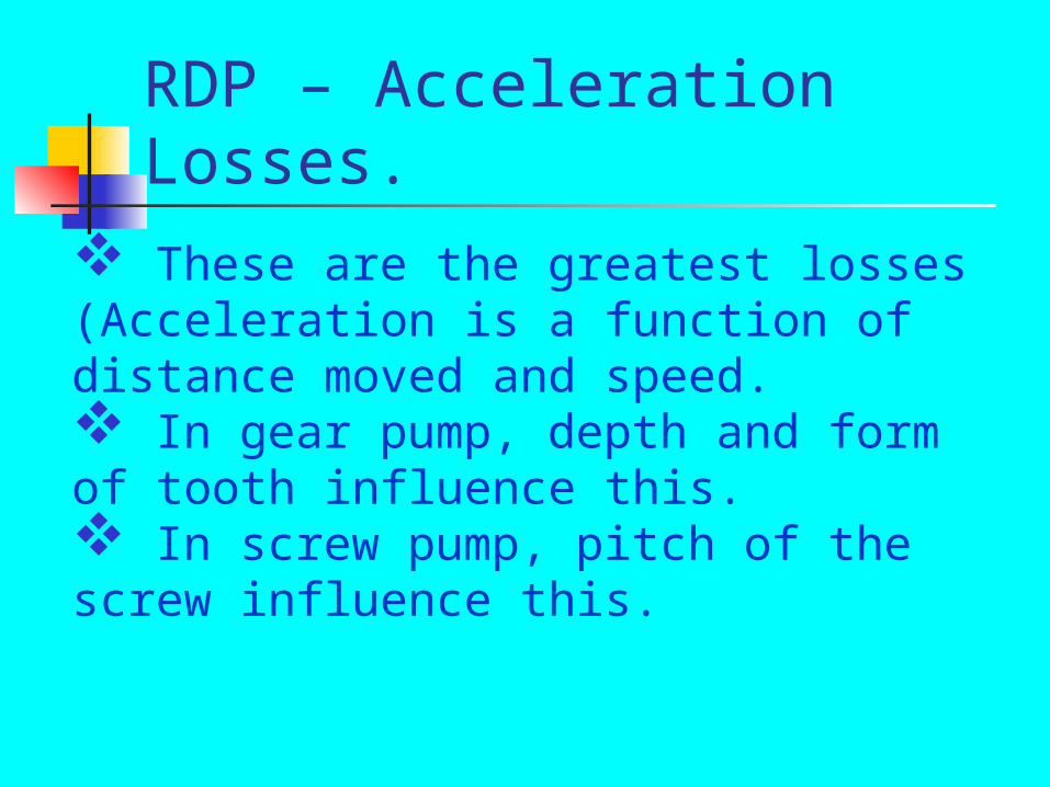
RDP – Acceleration Losses. These are the greatest losses (Acceleration is a function of distance moved and speed. In gear pump, depth and form of tooth influence this. In screw pump, pitch of the screw influence this.
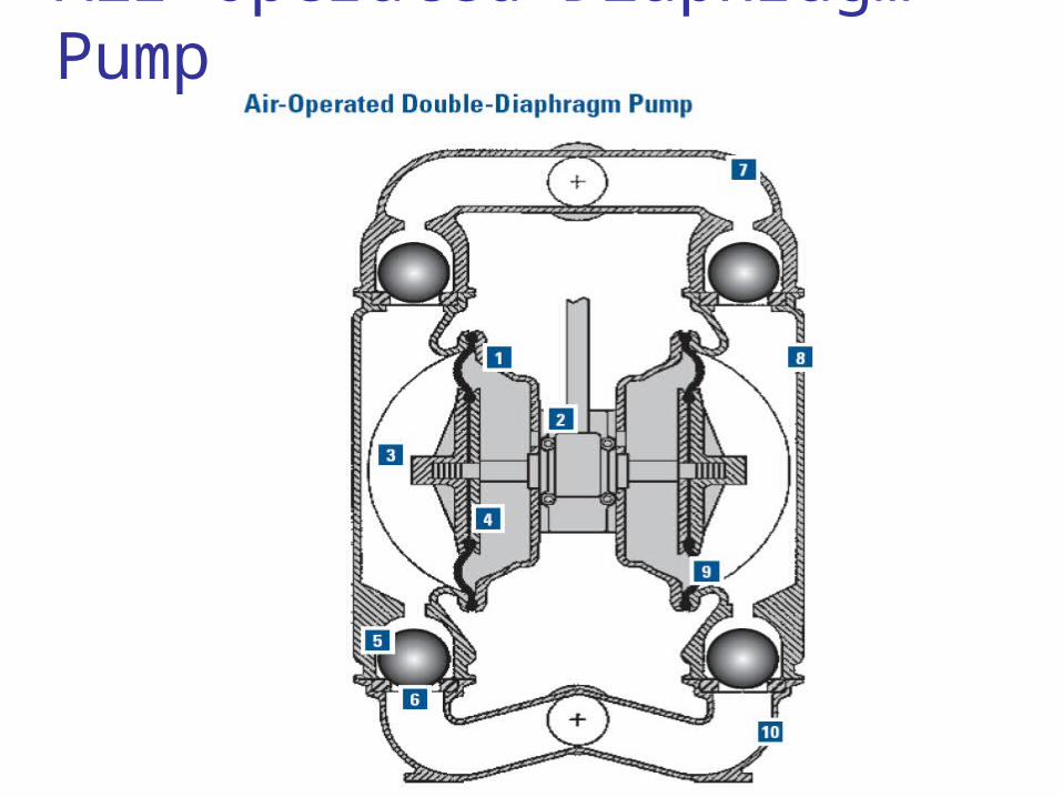
Air Operated Diaphragm Pump
Globe Valve
Piping Piping systems are used to convey fluids. The term ‘piping’ generally refers to the pipe, valves, fittings, flanges, and other components. Fittings – Everything in a system except pipes. Pipe and tubing – No definite rule for distinguishing between pipe and tubing. One difference is wall thickness: typically, pipe has heavier walls. Pipe generally conveys fluid flow from one location to another, whereas tubing may direct static pressure for control or measurement. The term tubing also applies to the cylindrical elements that separate fluids in boilers and other heat exchangers.
Piping Materials joined in a piping system must be similar, to avoid galvanic corrosion (where different metals connected and mutually in contact with seawater; the metal which comes later in the galvanic series may corrode – acts like a sacrificial anode). Example of galvanic series – Zinc, Aluminium, Carbon Steels, Cast Iron, Lead-Tin alloy, Lead, Brass, Copper, Bronze, Gunmetal, Copper-Nickel Iron, Monel Metal etc. Pipe and fitting strength is affected by temperature as well as pressure, and both must be considered in the selection of materials and wall thickness. As temperature increases, material strength decreases. Higher pressure results in higher stresses on components.
Piping Pipe is sized by nominal pipe size (NPS). The nominal pipe size is based on nominal inside diameter for sizes up to 300 mm. Since the pipe is joined using standard size fittings, the outside diameter must be the same regardless of wall thickness. Consequently, pipe wall thickness is achieved by adjusting the inside diameter. For larger pipe sizes (350mm and more), the nominal pipe size is based on the outside diameter. Seamed pipe is formed by rolling a flat plate into a cylindrical shape and then welding along the longitudinal seam. Seamless pipe is formed by a drawing process where red-hot metal is drawn over a piercing mandrel, forming the tubular shape directly.
Piping
Pipe threads differ from machine threads in that they are cut on a taper i.e., the thread diameter is smaller at the end of the pipe and progressively larger along the pipe length. As a result of the taper, when the pipe is screwed into a fitting, the threads force and increasing interference that assists in sealing against leakage. Compounds are applied to the external threads to any imperfections. Teflon tape or teflon-bearing pipe dope used on lower temperature connections and lubricants bearing copper or silver metal flakes are used in higher pressure, higher temperature joints. These compounds also prevent galling of the threads and seizing, thereby facilitating future disassembly for maintenance or repair.
Piping Flanges consist of flat-faced disks that are bolted together, with a compliant gasket material installed between them. For high-pressure piping, it is standard practice to use raised-face flanges, where the flange face in the area within the bolt holes is raised to increase compression of the gasket in the sealing area. It should be noted that in any installation using cast-iron valves, raised face should not be used on the flanges. Using flat faces with cast iron avoids high bending stresses on the cast-iron flange. Welded joints are used for general purpose piping and are required for high-pressure, high-temperature piping systems. Two types - socket-welded fittings and butt-welded fittings are used. Larger–bore pipe systems are made up using butt-welded fittings.
Piping
Steel – Subject to galvanic action and rusting.Mild steel pipes for seawater are protected by being galvanized or rubber lined.Mild steel ERW or hot rolled pipes are galvanized by hot-dipping.Seamless mild steel pipes- used for (less than 460oc) steam, high pressure air, feed discharges and all fuel oil pressure piping. For greater than 460oc applications steel requires additions of alloying materials like Molybdenum and Chromium.
PipingCast Iron – Poor corrosion resistance in seawater, especially vulnerable to graphitization.Weakness of Grey Cast Iron – In tension, and under shock loading. It is brittle in nature. Hence limits applications to low pressure requirements.Advantage – Ease of casting.Spheroidal Graphite Cast Iron ( S G Iron ) and Meehanite – High strength versions, suitable for use in shipside valves. S G Iron also used for high pressure service and steam below 460oc.
Pipingo Copper pipes – Suitable for moderate temperature and pressure.o Stainless Steel – Widely used for cargo pipes of chemical tankers carrying very corrosive cargoes.o Non-ferrous alloys – Brass is an alloy of copper and zinc. Bronze is an alloy of copper and tin. In both the cases there may be additions of other metals. Aluminium brass is also widely used. All these are resistant to seawater corrosion. Non-ferrous alloys are protected from corrosion by deposition of iron ions, if iron or steel fittings are used. Iron ion protection can also be supplied from sacrificial or driven iron anodes by dosing with ferrous sulphate.o Brasses in presence of seawater undergo dezincification. Remedy- Addition of arsenic (0.04%) or other metals.o Some brasses prone to corrosion-stress cracking.
Piping Erosion – Result of abrasives, high water speed, entrained air, turbulence, cavitation. Turbulence and cavitation often caused by protuberances, high bends, abrupt change of pipe cross-sectional area, incorrectly cut jointing, weld deposits. Temperature – Above 450oc cause recrystallization & creep in iron and steel. Low temperature (-162oc) as in liqified natural gas; cause brittle failure. Varying temperatures cause stresses due to expansion and contraction. Pipe fittings – Cast iron & gunmetal fittings are used for small sizes and moderate pressure. Cast or fusion welded (fabricated) mild steel or S G iron are used for high pressure and temperature and fuel oil under pressure. 0.5% molybdenum steel used for temp: greater than 460oc- Molybdenum inhibits recrystallisation and therefore the resulting creep.
Pipe Installations Vibration is the frequent cause of eventual pipe failure. Supports and clips (must permit free expansion and contraction) are used to prevent this. It is essential that pipe systems and heavy valve chests are seperately supported and stayed. Flanged connection to the pumps to be the last to be coupled after faces are correctly aligned. Expansion arrangements – to accommodate changes in length due to change in temperature (to prevent undue stress or distortion). Methods– Anchored sleeve with stuffing box & gland, right angle bend or loop, stainless steel bellows or expansion joint. Water-tight bulkhead- Pipes carried thorough water-tight bulkheads, use special fittings to avoid impairment of their integrity. Drains– For steam pipes to avoid water-hammer

Expansion bellows

Expansion joints, bellows
Max: and Min: temperature to be considered when choosing bellows. while installing do not over-compress or over-extend. Usually the material is stainless steel upto 500oc. Normally bellows have internal sleeves to give smooth flow. Fit the bellows in correct direction. Bellows will absorb movement or vibration in several planes, eliminating maintenance; reduce friction and heat losses.
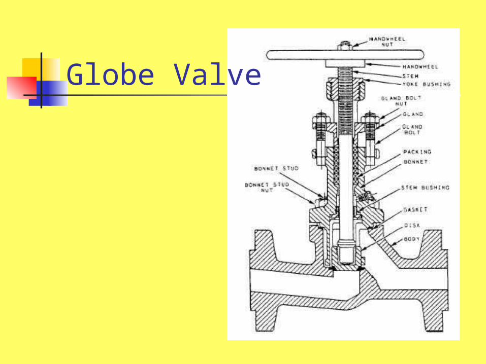
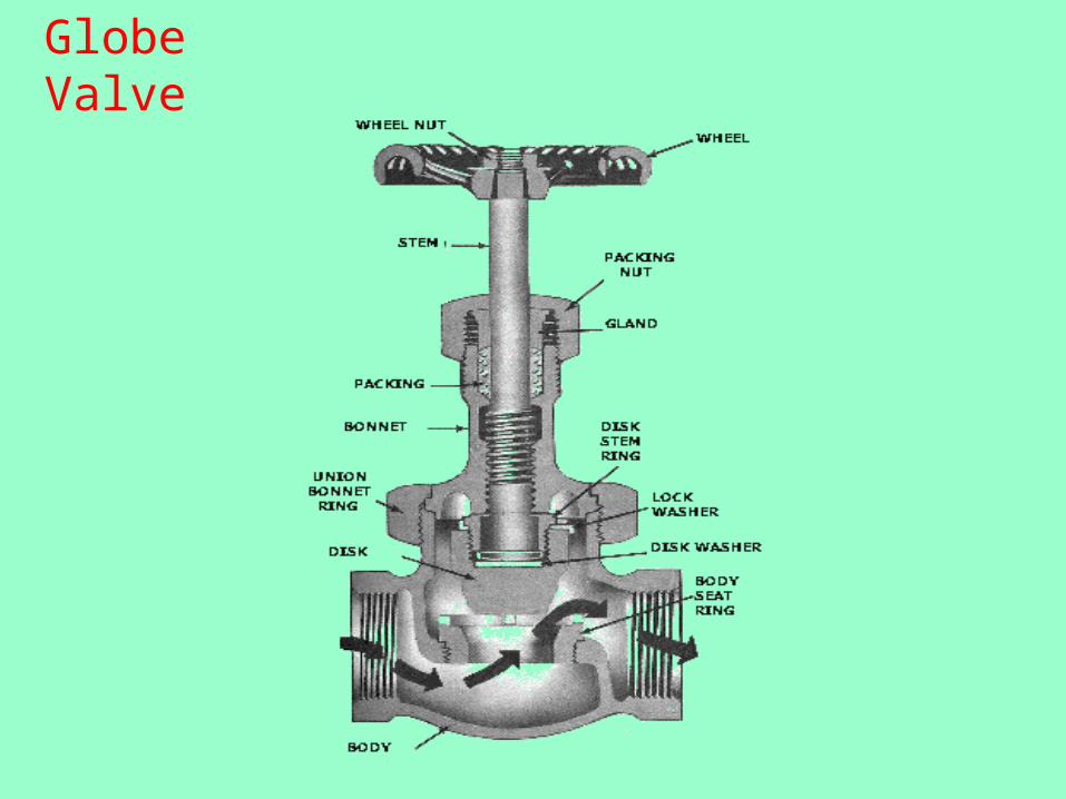
Globe Valve
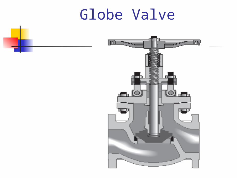
Globe Valve
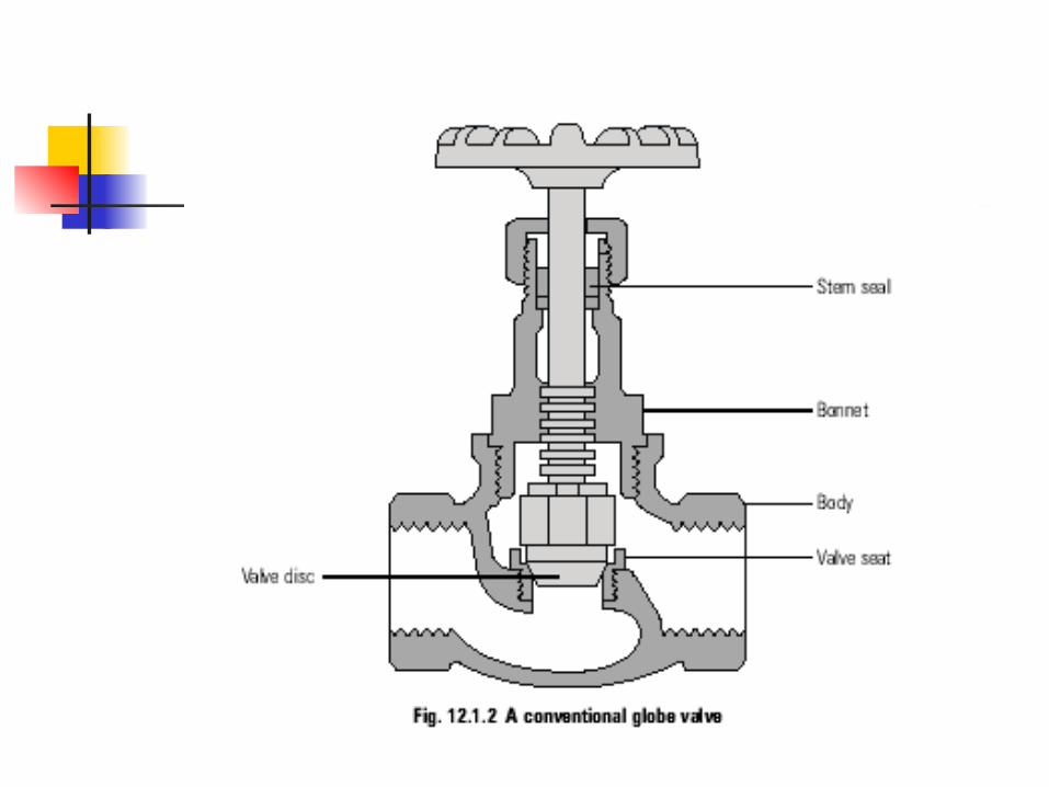
Globe Valve
Bulbous body, valve seat, screw down plug or disc arranged at right angles to the axis of the pipe. Sometimes both seat and disc faces are stellited or seat may be renewable and screwed into the valve chest or given a light interference fit and secured by grub screw. Seating may be flat or mitered (common). Spindle or stem may have a vee or square thread. Leakage along spindle arrested by stuffing box. If there is any change in direction angle valve is used.
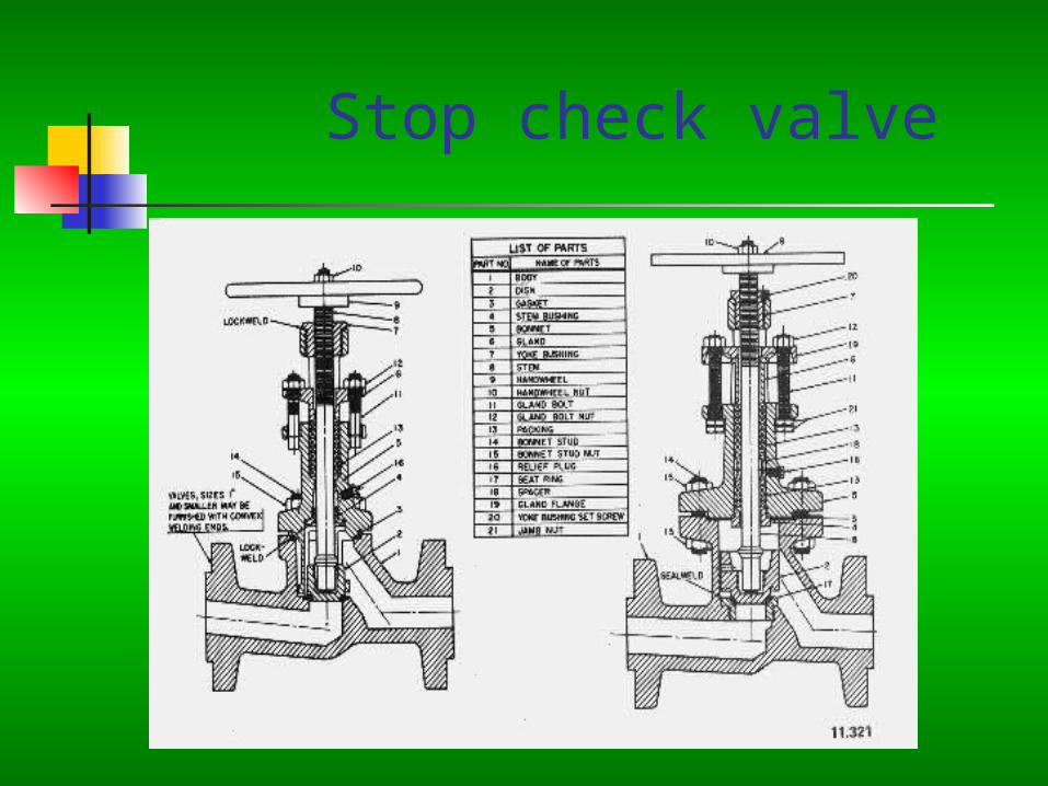
Stop check valve
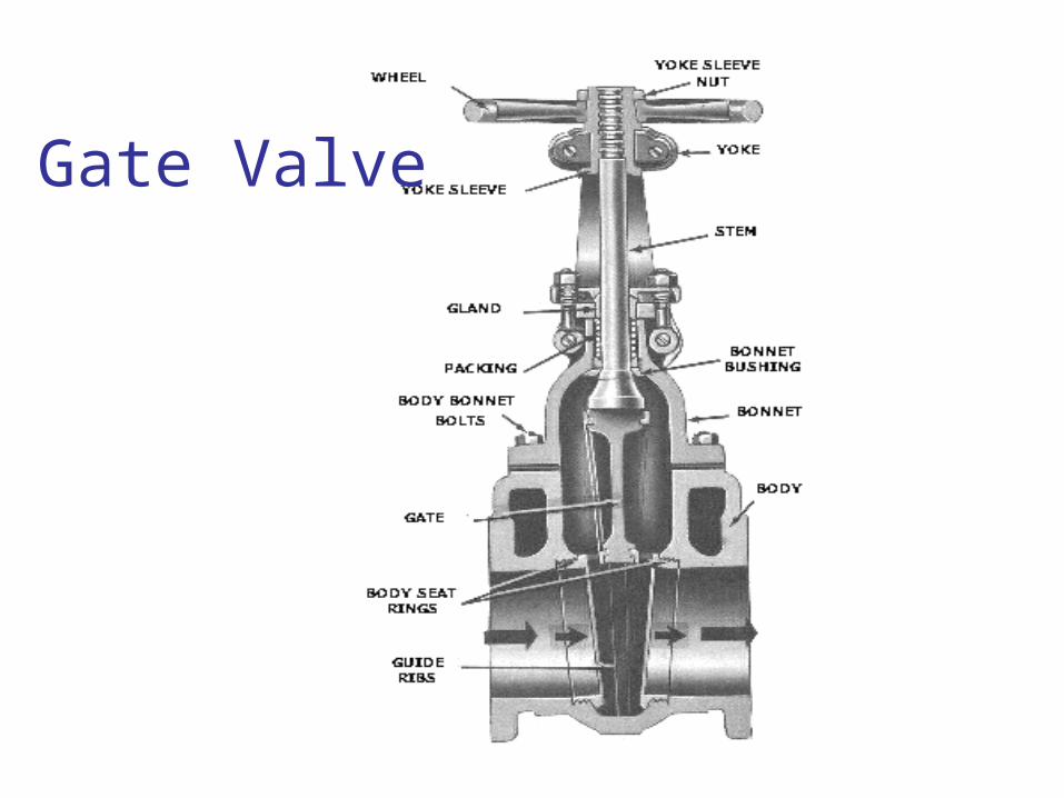
Gate Valve
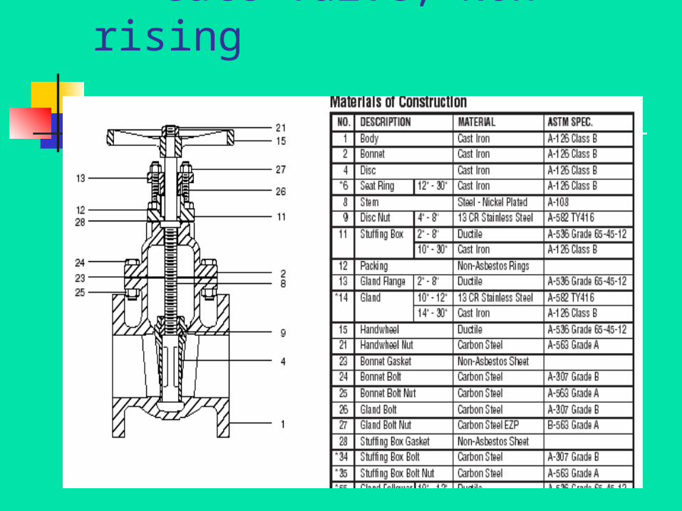
Gate Valve, Non rising
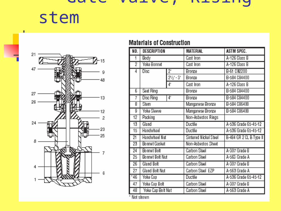
Gate Valve, Rising stem
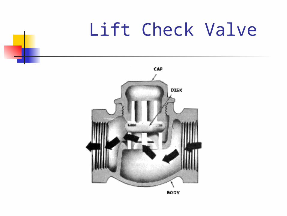
Lift Check Valve
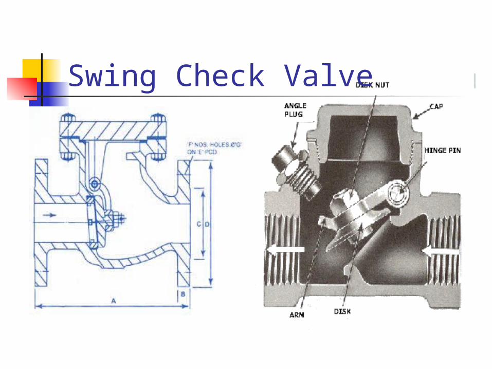
Swing Check Valve
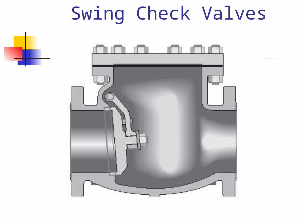
Swing Check Valves
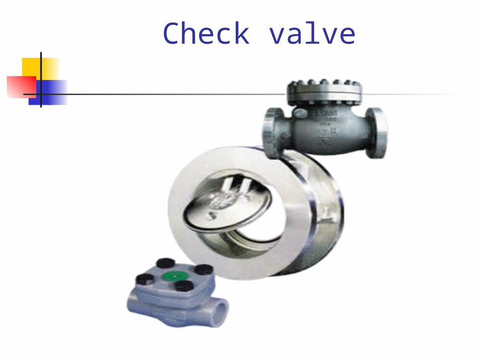
Check valve
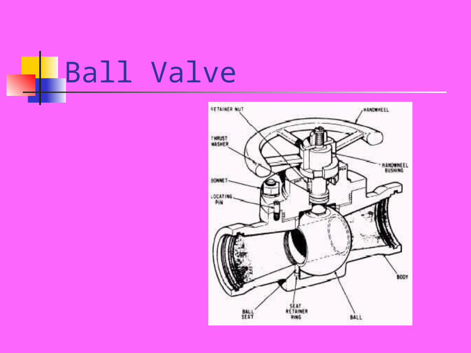
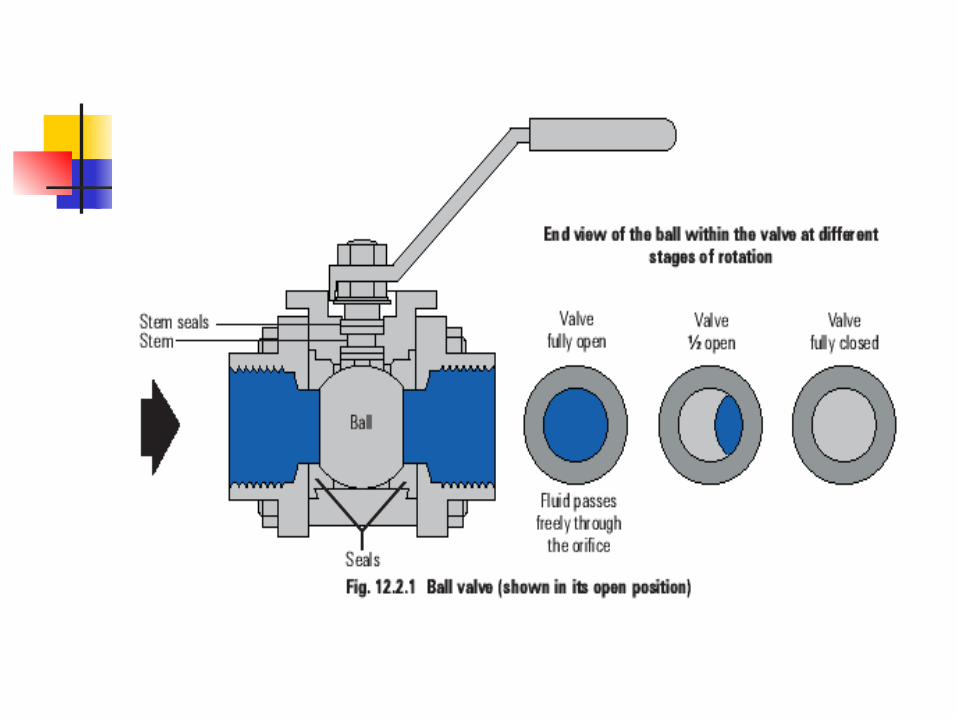
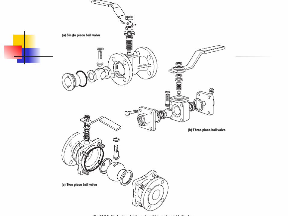
Ball Valve
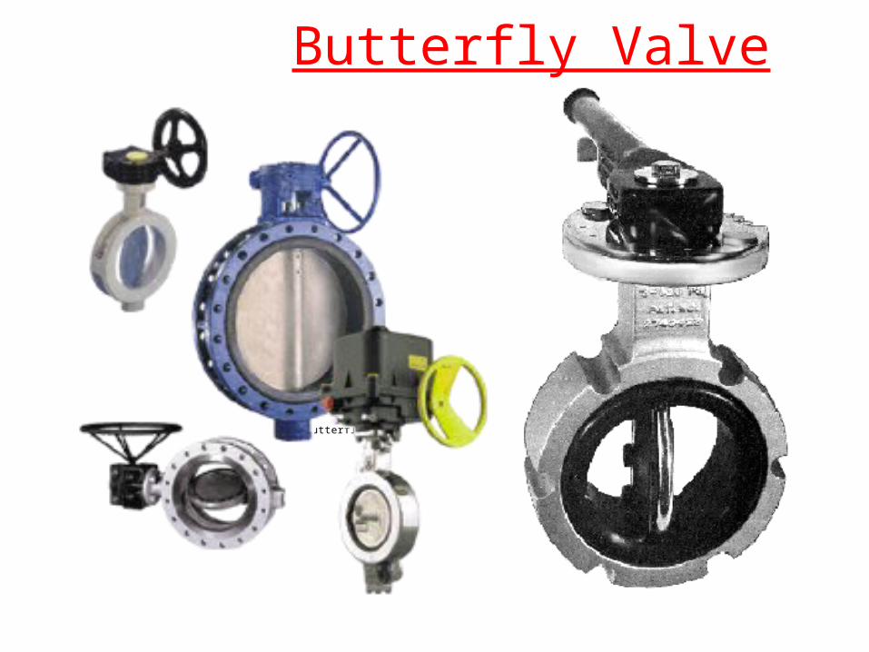
Butterfly Valve
Butterfly.gif
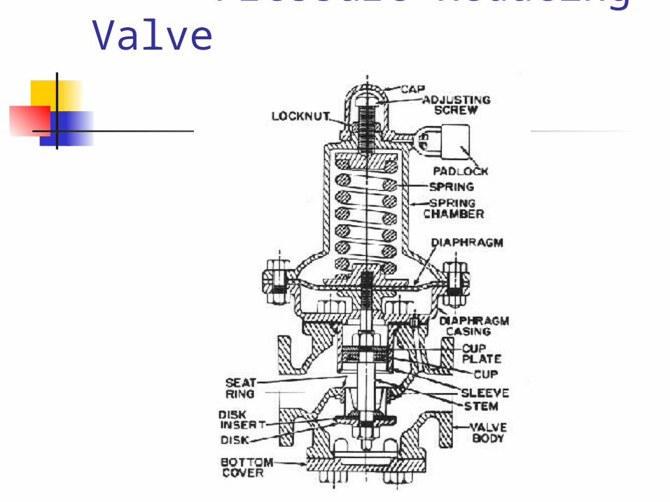
Pressure Reducing Valve
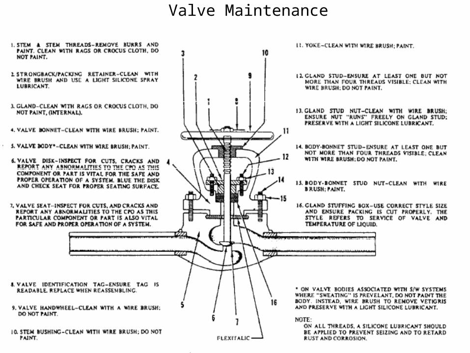
Valve Maintenance
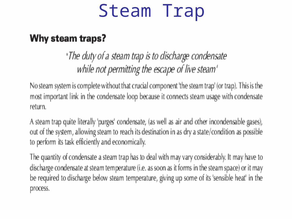
Steam Trap
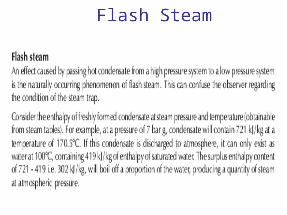
Flash Steam
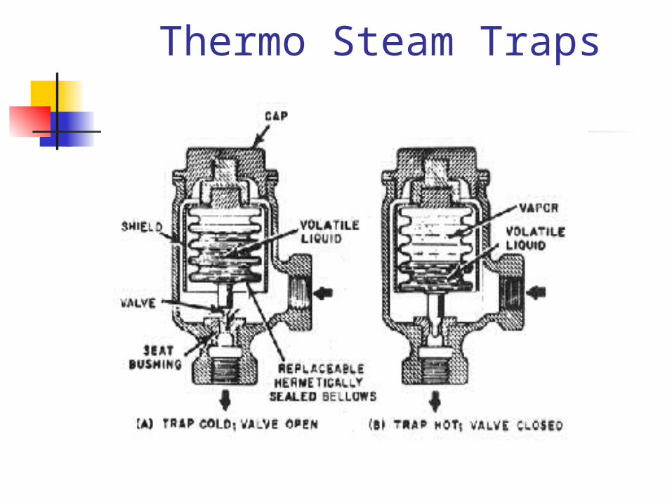
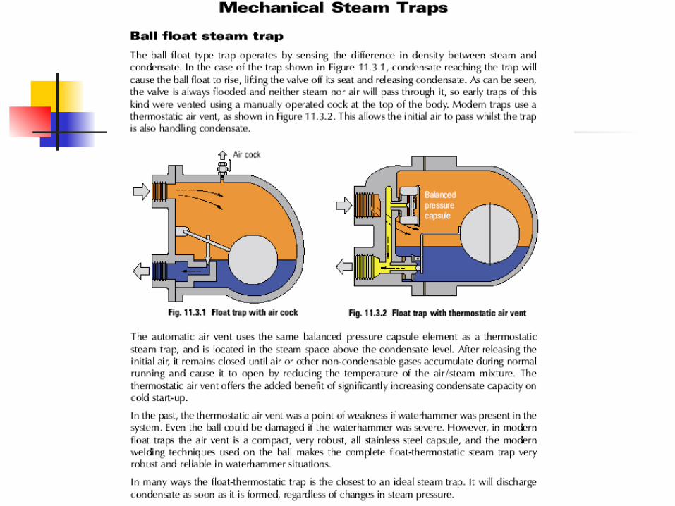
Thermo Steam Traps
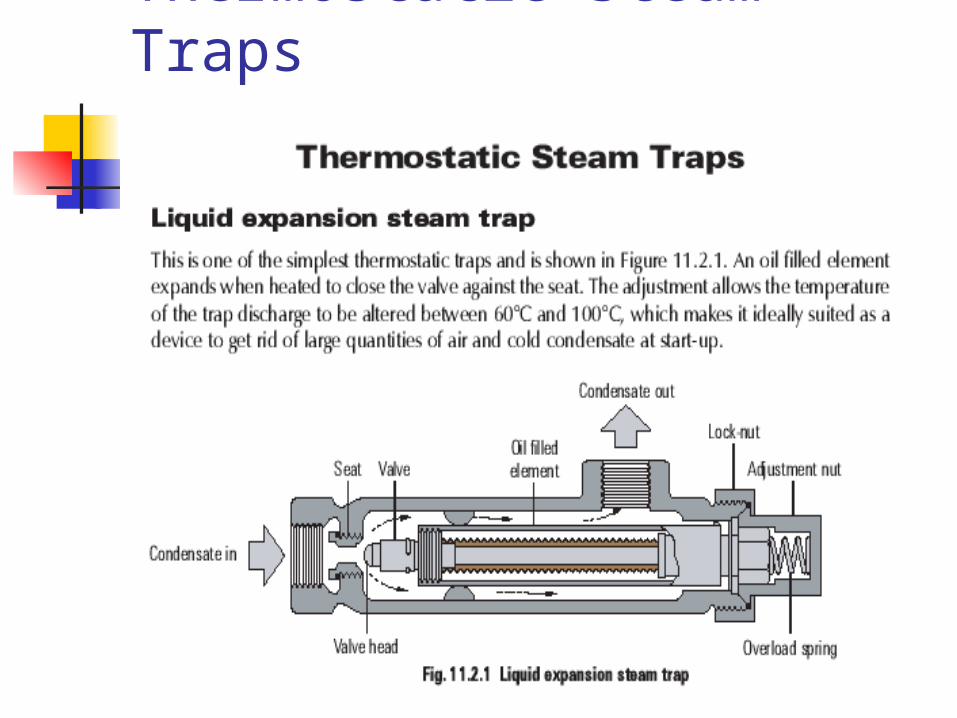
Thermostatic Steam Traps
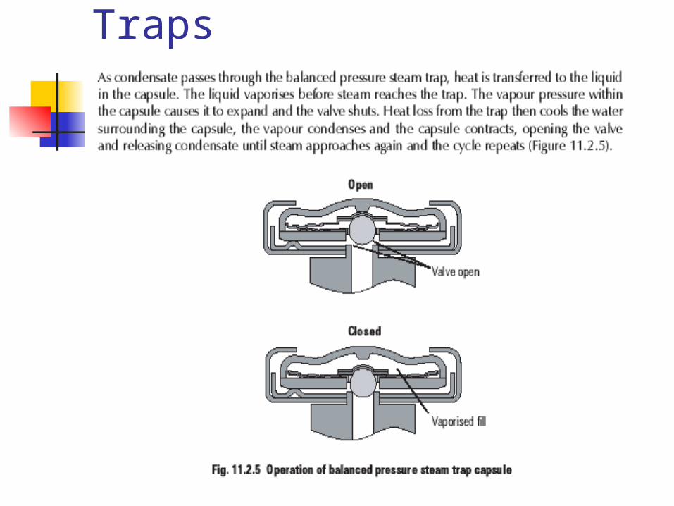
Balanced Steam Traps
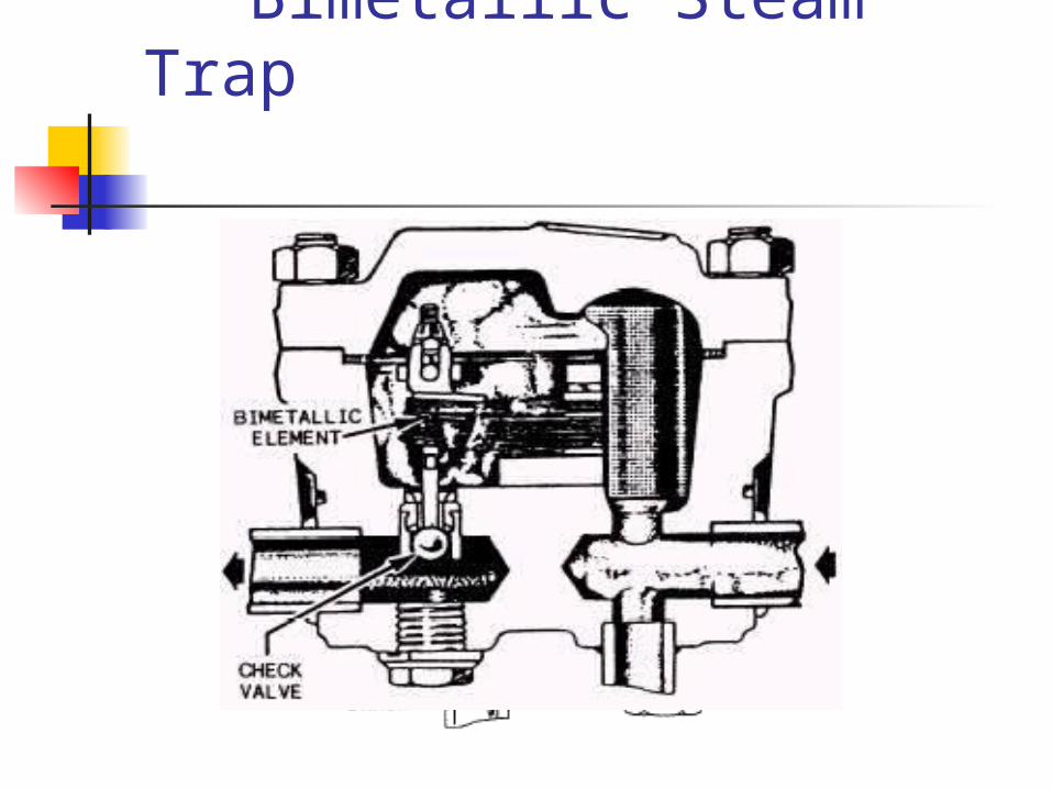
Bimetallic Steam Trap
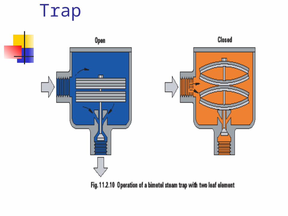
Bimetallic Steam Trap
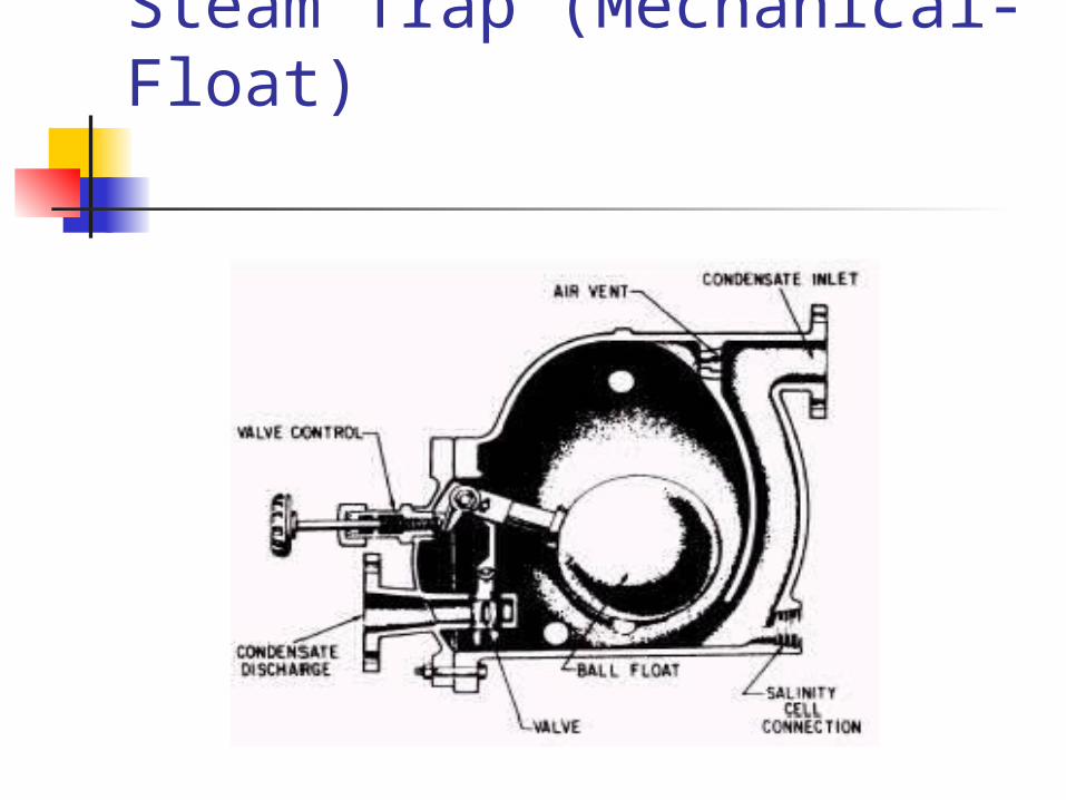
Steam Trap (Mechanical- Float)
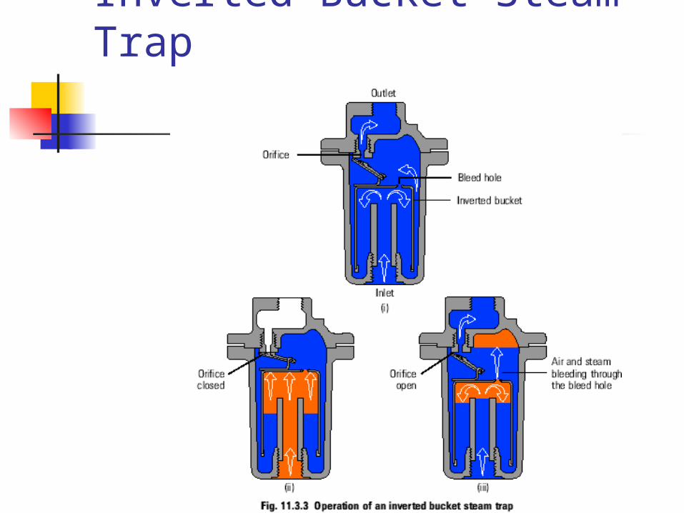
Inverted Bucket Steam Trap
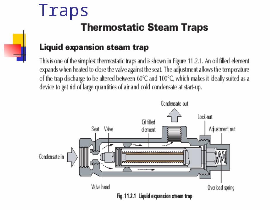
Thermostatic Steam Traps
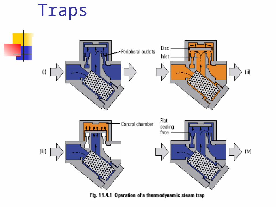
Thermodynamic Steam Traps
Thermodynamic Steam Traps
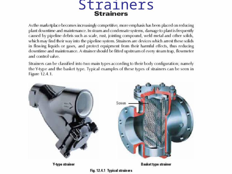
Strainers
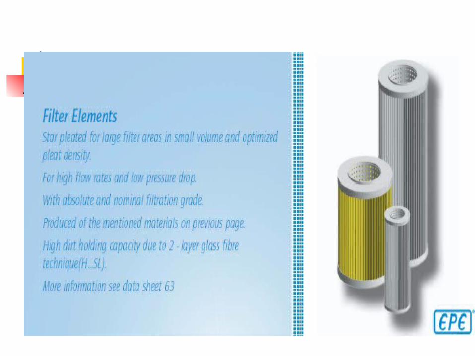
Filter Elements
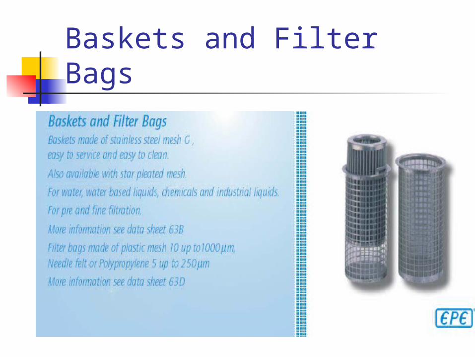
Baskets and Filter Bags
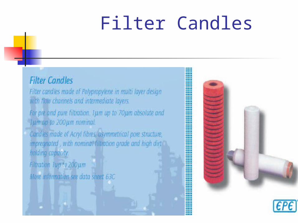
Filter Candles
Coupling
Gaskets
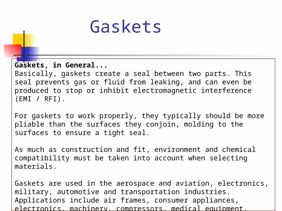
Gaskets, in General...Basically, gaskets create a seal between two parts. This seal prevents gas or fluid from leaking, and can even be produced to stop or inhibit electromagnetic interference (EMI / RFI). For gaskets to work properly, they typically should be more pliable than the surfaces they conjoin, molding to the surfaces to ensure a tight seal. As much as construction and fit, environment and chemical compatibility must be taken into account when selecting materials. Gaskets are used in the aerospace and aviation, electronics, military, automotive and transportation industries. Applications include air frames, consumer appliances, electronics, machinery, compressors, medical equipment, meters, turbines and valves.
GASKETS
There are many materials from which gaskets can be manufactured... Rubber materials include; neoprene, Hypalon, pure gum, Viton and food grade rubbers (FDA, silicone sponge rubbers. Plastics include; Teflon, nylon, polyethylene (PE), polyurethane, Mylar. Non-asbestos sheets, such as carbon filament, fiberglass, ceramic and Kevlar. Other soft materials include; compressed sheet, composition cork, felt, vegetable fiber and papers. Polyether, polyester and filter foam are three types of foam rubber. Gaskets can be made of metal such as; carbon steel, stainless steel, nickel, aluminum, brass and copper.