Embed Size (px)
Citation preview
External Use
TM
Functional Safety Compliance
Throughout the Vehicle with
SafeAssure Solutions
FTF-AUT-F0009
A P R . 2 0 1 4
Richard Soja | Automotive MCU Systems Engineer
TM
External Use 1
Agenda
• Functional Safety at Freescale
• Functional Safety and Microcontrollers
• MCU Safety Context and Safety Concepts
• Dynamic FMEDA
• Safety Manual
TM
External Use 2
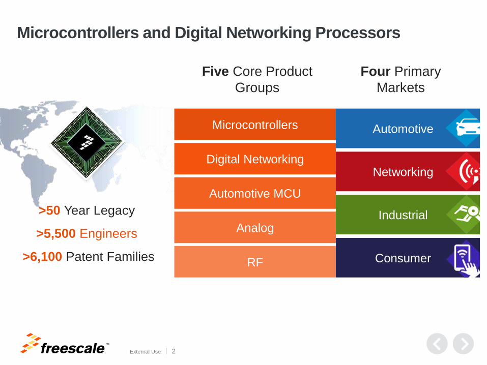
Microcontrollers and Digital Networking Processors
>50 Year Legacy
>5,500 Engineers
>6,100 Patent Families
Microcontrollers
Digital Networking
Automotive MCU
Analog
RF
Five Core Product
Groups
Four Primary
Markets
Automotive
Networking
Industrial
Consumer
TM
External Use 3
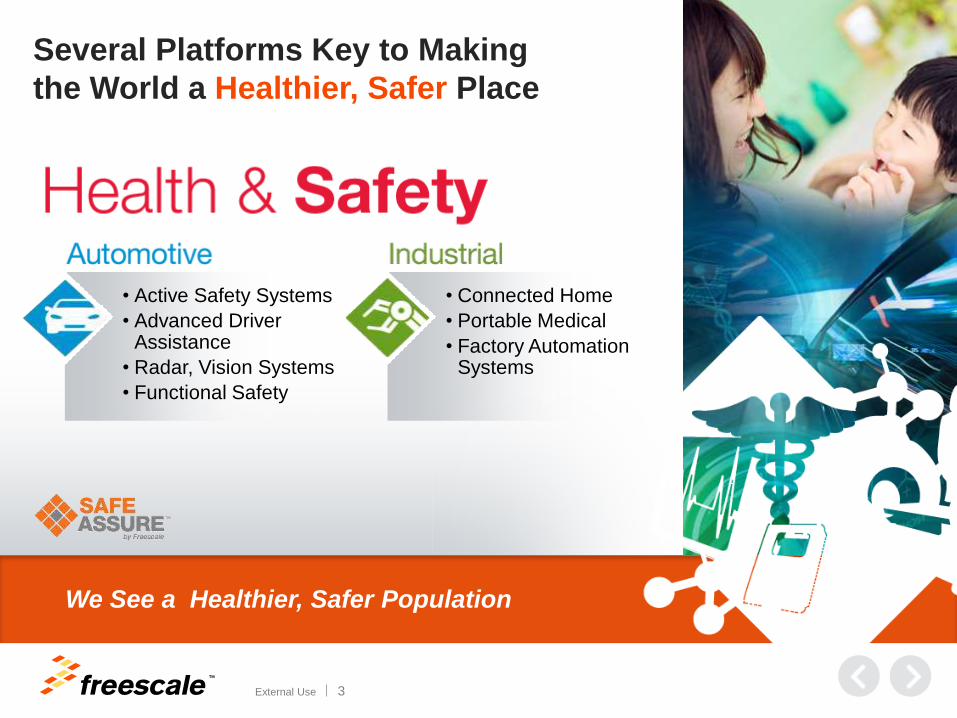
Several Platforms Key to Making
the World a Healthier, Safer Place
• Active Safety Systems
• Advanced Driver Assistance
• Radar, Vision Systems
• Functional Safety
• Connected Home
• Portable Medical
• Factory Automation Systems
We See a Healthier, Safer Population
TM
External Use 4
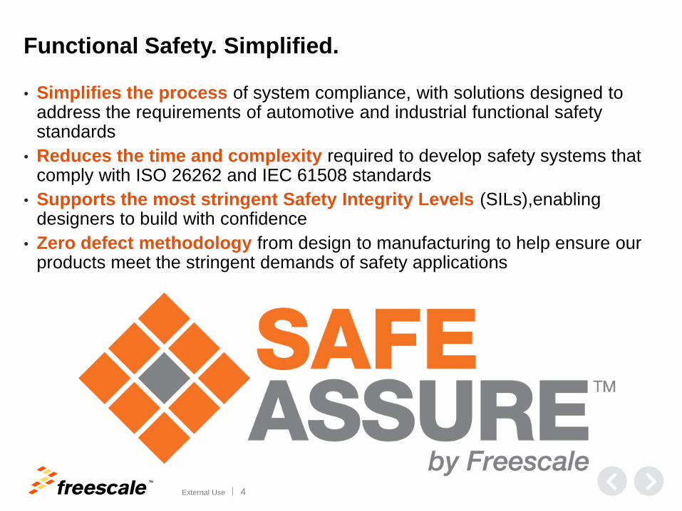
Functional Safety. Simplified.
• Simplifies the process of system compliance, with solutions designed to address the requirements of automotive and industrial functional safety standards
• Reduces the time and complexity required to develop safety systems that comply with ISO 26262 and IEC 61508 standards
• Supports the most stringent Safety Integrity Levels (SILs),enabling designers to build with confidence
• Zero defect methodology from design to manufacturing to help ensure our products meet the stringent demands of safety applications
TM
External Use 5
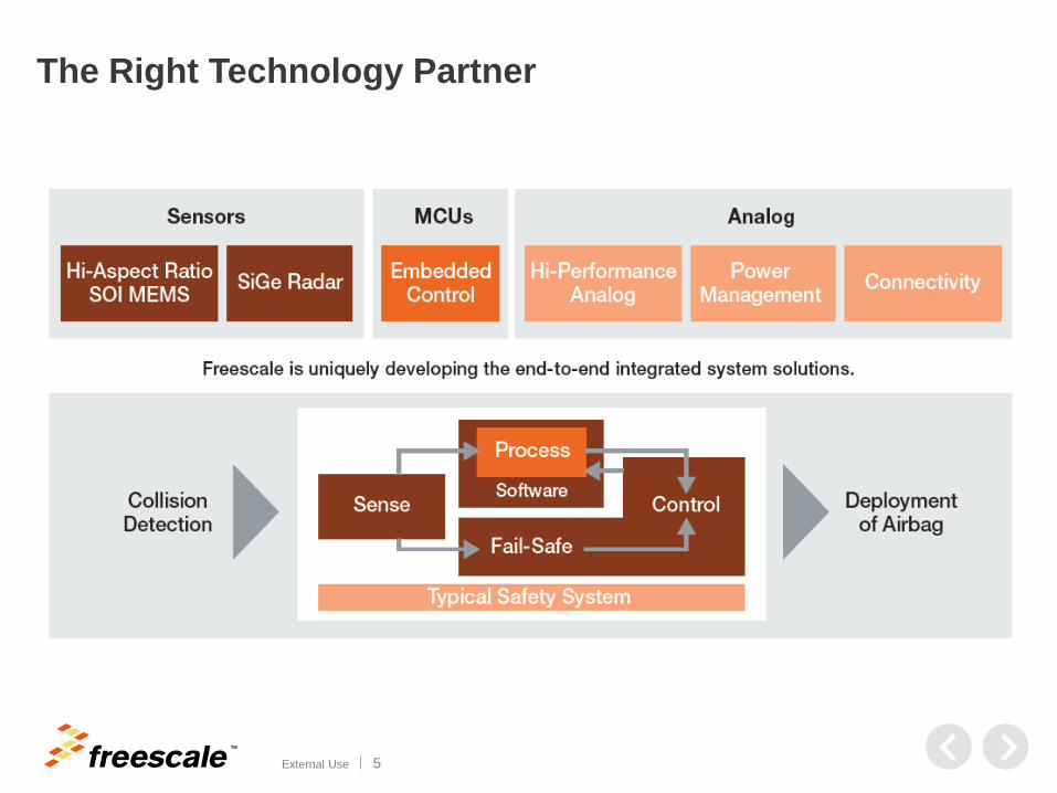
The Right Technology Partner
TM
External Use 6
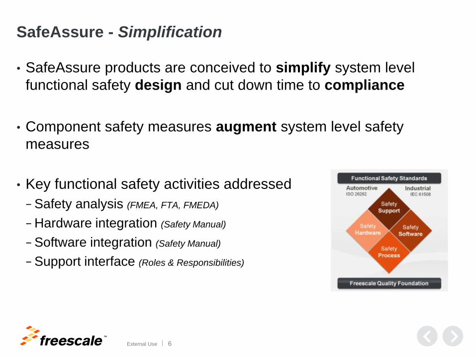
SafeAssure - Simplification
• SafeAssure products are conceived to simplify system level
functional safety design and cut down time to compliance
• Component safety measures augment system level safety
measures
• Key functional safety activities addressed
− Safety analysis (FMEA, FTA, FMEDA)
− Hardware integration (Safety Manual)
− Software integration (Safety Manual)
− Support interface (Roles & Responsibilities)
TM
External Use 7
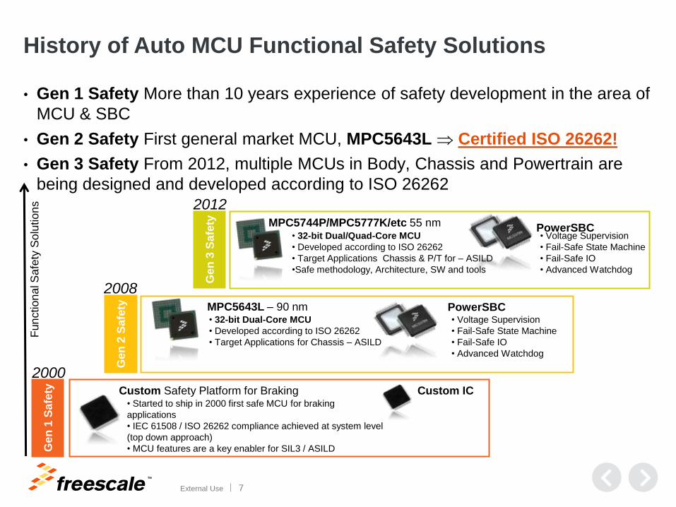
History of Auto MCU Functional Safety Solutions
• Gen 1 Safety More than 10 years experience of safety development in the area of
MCU & SBC
• Gen 2 Safety First general market MCU, MPC5643L Certified ISO 26262!
• Gen 3 Safety From 2012, multiple MCUs in Body, Chassis and Powertrain are
being designed and developed according to ISO 26262
Ge
n 1
Sa
fety
Ge
n 2
Sa
fety
Ge
n 3
Sa
fety
MPC5744P/MPC5777K/etc 55 nm
2000
2008
PowerSBC
MPC5643L – 90 nm
Custom Safety Platform for Braking
Fun
ctio
nal S
afe
ty S
olu
tion
s
PowerSBC
2012
• Voltage Supervision
• Fail-Safe State Machine
• Fail-Safe IO
• Advanced Watchdog
• Voltage Supervision
• Fail-Safe State Machine
• Fail-Safe IO
• Advanced Watchdog
• 32-bit Dual-Core MCU
• Developed according to ISO 26262
• Target Applications for Chassis – ASILD
• 32-bit Dual/Quad-Core MCU
• Developed according to ISO 26262
• Target Applications Chassis & P/T for – ASILD
•Safe methodology, Architecture, SW and tools
• Started to ship in 2000 first safe MCU for braking
applications
• IEC 61508 / ISO 26262 compliance achieved at system level
(top down approach)
• MCU features are a key enabler for SIL3 / ASILD
Custom IC
TM
External Use 8
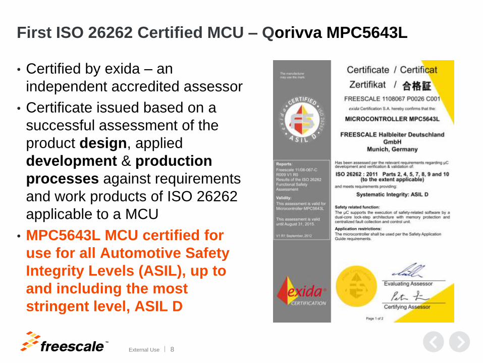
First ISO 26262 Certified MCU – Qorivva MPC5643L
• Certified by exida – an
independent accredited assessor
• Certificate issued based on a
successful assessment of the
product design, applied
development & production
processes against requirements
and work products of ISO 26262
applicable to a MCU
• MPC5643L MCU certified for
use for all Automotive Safety
Integrity Levels (ASIL), up to
and including the most
stringent level, ASIL D

TM
External Use 9
Agenda
• Functional Safety at Freescale
• Functional Safety and Microcontrollers
• MCU Safety Context and Safety Concepts
• Dynamic FMEDA
• Safety Manual
TM
External Use 10
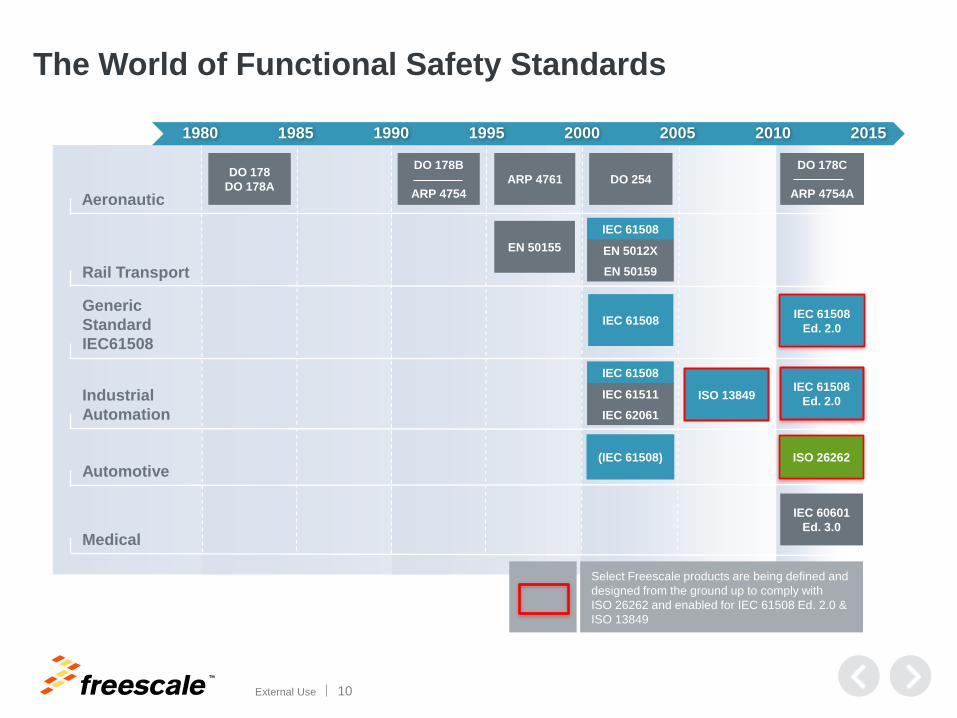
The World of Functional Safety Standards
Generic
Standard
IEC61508
Industrial
Automation
Rail Transport
Automotive
Aeronautic
1980 1985 1990 1995 2000 2005 2010 2015
ISO 26262
IEC 61508 IEC 61508
Ed. 2.0
IEC 61508
Ed. 2.0
EN 50155
IEC 61508
EN 5012X
EN 50159
(IEC 61508)
DO 178
DO 178A ARP 4761 DO 254
Medical
IEC 60601
Ed. 3.0
Select Freescale products are being defined and
designed from the ground up to comply with
ISO 26262 and enabled for IEC 61508 Ed. 2.0 &
ISO 13849
DO 178B
ARP 4754
DO 178C
ARP 4754A
IEC 61508
IEC 61511
IEC 62061
ISO 13849
TM
External Use 11
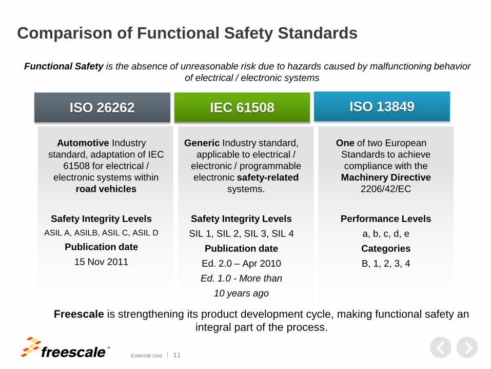
Automotive Industry
standard, adaptation of IEC
61508 for electrical /
electronic systems within
road vehicles
Safety Integrity Levels
ASIL A, ASILB, ASIL C, ASIL D
Publication date
15 Nov 2011
Generic Industry standard,
applicable to electrical /
electronic / programmable
electronic safety-related
systems.
Safety Integrity Levels
SIL 1, SIL 2, SIL 3, SIL 4
Publication date
Ed. 2.0 – Apr 2010
Ed. 1.0 - More than
10 years ago
ISO 26262 IEC 61508 ISO 13849
Freescale is strengthening its product development cycle, making functional safety an
integral part of the process.
One of two European
Standards to achieve
compliance with the
Machinery Directive
2206/42/EC
Performance Levels
a, b, c, d, e
Categories
B, 1, 2, 3, 4
Comparison of Functional Safety Standards
Functional Safety is the absence of unreasonable risk due to hazards caused by malfunctioning behavior
of electrical / electronic systems
TM
External Use 12
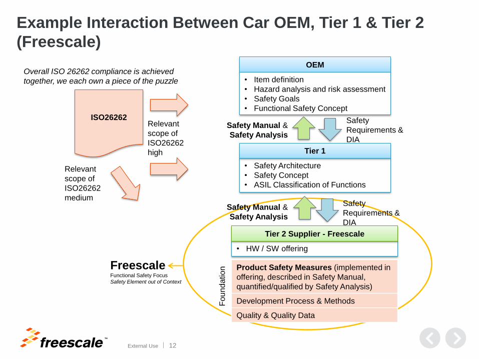
Example Interaction Between Car OEM, Tier 1 & Tier 2
(Freescale)
OEM
• Safety Architecture
• Safety Concept
• ASIL Classification of Functions
Tier 1
• HW / SW offering
Tier 2 Supplier - Freescale
• Item definition
• Hazard analysis and risk assessment
• Safety Goals
• Functional Safety Concept ISO26262 Safety
Requirements &
DIA
Safety
Requirements &
DIA
Safety Manual &
Safety Analysis
Relevant
scope of
ISO26262
high
Fou
nd
atio
n
Product Safety Measures (implemented in
offering, described in Safety Manual,
quantified/qualified by Safety Analysis)
Development Process & Methods
Quality & Quality Data
Relevant
scope of
ISO26262
medium
Overall ISO 26262 compliance is achieved
together, we each own a piece of the puzzle
Freescale Functional Safety Focus
Safety Element out of Context
Safety Manual &
Safety Analysis
TM
External Use 13
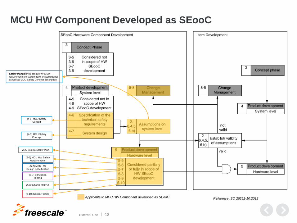
MCU HW Component Developed as SEooC
Reference ISO 26262-10:2012 Applicable to MCU HW Component developed as SEooC
(4-6) MCU Safety
Context
(4-7) MCU Safety
Concept
Safety Manual includes all HW & SW
requirements on system level (Assumptions)
as well as MCU Safety Concept description
(5-6) MCU HW Safety
Requirements
(5-7) MCU HW
Design Specification
(5-8,9) MCU FMEDA
MCU SEooC Safety Plan
(5-7) Simulation
Testing
(5-10) Silicon Testing
TM
External Use 14
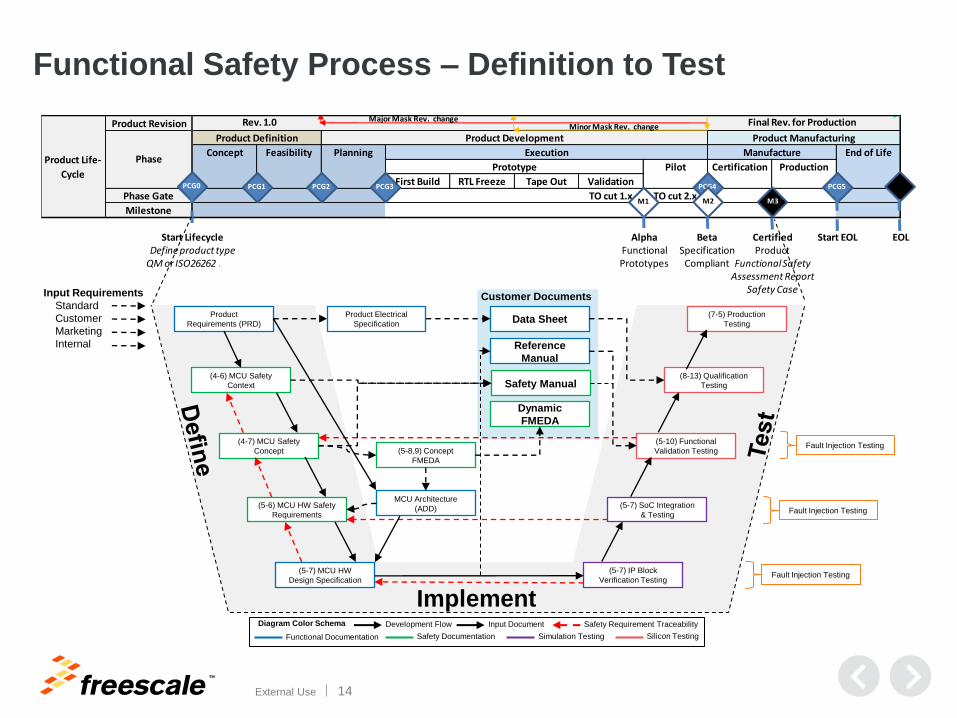
Functional Safety Process – Definition to Test
Product Revision
First Build RTL Freeze Tape Out Validation
Phase Gate TO cut 1.x TO cut 2.x
Milestone
Product Life-
Cycle
Phase
Product Definition Product Development Product Manufacturing
Concept Feasibility Planning Execution Manufacture End of Life
Prototype Pilot Certification Production
PCG0 PCG1 PCG2 PCG3 PCG4 PCG5
M1 M2 M3
Start LifecycleDefine product type
QM or ISO26262 ASIL
Rev. 1.0 Final Rev. for ProductionMajor Mask Rev. changeMinor Mask Rev. change
Certified Product
Functional SafetyAssessment Report
Safety Case
BetaSpecification
Compliant
AlphaFunctionalPrototypes
Start EOL EOL
(4-6) MCU Safety
Context
(4-7) MCU Safety
Concept
(5-6) MCU HW Safety
Requirements
(5-7) MCU HW
Design Specification
(5-8,9) Concept
FMEDA
(5-10) Functional
Validation Testing
(5-7) IP Block
Verification Testing
(8-13) Qualification
Testing
(5-7) SoC Integration
& Testing
Implement
Safety Documentation Silicon Testing Simulation Testing Functional Documentation
Diagram Color Schema Development Flow Safety Requirement Traceability
Fault Injection Testing
Fault Injection Testing
Fault Injection Testing
Input Requirements
Standard
Customer
Marketing
Internal
Product
Requirements (PRD)
MCU Architecture
(ADD)
Data Sheet Product Electrical
Specification
Reference
Manual
Safety Manual
Dynamic
FMEDA
(7-5) Production
Testing
Customer Documents
Input Document
TM
External Use 15
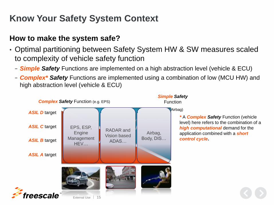
Know Your Safety System Context
How to make the system safe?
• Optimal partitioning between Safety System HW & SW measures scaled
to complexity of vehicle safety function
− Simple Safety Functions are implemented on a high abstraction level (vehicle & ECU)
− Complex* Safety Functions are implemented using a combination of low (MCU HW) and
high abstraction level (vehicle & ECU)
MCU HW
Complex Safety Function (e.g. EPS)
Simple Safety
Function
(e.g. Airbag)
EPS, ESP,
Engine
Management
HEV…
ASIL D target
ASIL A target
ASIL B target
ASIL C target
* A Complex Safety Function (vehicle
level) here refers to the combination of a
high computational demand for the
application combined with a short
control cycle.
Safety System
HW & SW
Airbag,
Body, DIS…
RADAR and
Vision based
ADAS…
TM
External Use 16
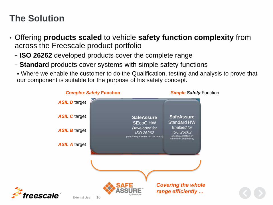
The Solution
• Offering products scaled to vehicle safety function complexity from across the Freescale product portfolio
− ISO 26262 developed products cover the complete range
− Standard products cover systems with simple safety functions
Where we enable the customer to do the Qualification, testing and analysis to prove that our component is suitable for the purpose of his safety concept.
MCU
HW
Covering the whole
range efficiently …
ASIL D target
Complex Safety Function Simple Safety Function
ASIL A target
ASIL B target
ASIL C target EPS, ESP,
Engine
Management
HEV…
Safety System
HW & SW
Airbag,
Body, DIS…
RADAR and
Vision based
ADAS…
SafeAssure
SEooC HW Developed for
ISO 26262 (10.9 Safety Element out of Context)
SafeAssure
Standard HW Enabled for
ISO 26262 (8.13 Qualification of
Hardware Components)
TM
External Use 17
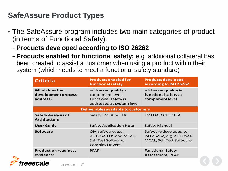
SafeAssure Product Types
• The SafeAssure program includes two main categories of product (in terms of Functional Safety):
− Products developed according to ISO 26262
− Products enabled for functional safety; e.g. additional collateral has been created to assist a customer when using a product within their system (which needs to meet a functional safety standard)
Criteria Products enabled for functional safety
Products developed according to ISO 26262
What does the development process address?
addresses quality at component level.Functional safety is addressed at system level
addresses quality & functional safety at component level
Deliverables available to customers
Safety Analysis of Architecture
Safety FMEA or FTA FMEDA, CCF or FTA
User Guide Safety Application Note Safety Manual
Software QM software, e.g. AUTOSAR OS and MCAL, Self Test Software, Complex Drivers
Software developed to ISO 26262, e.g. AUTOSAR MCAL, Self Test Software
Production readiness evidence:
PPAP Functional Safety Assessment, PPAP
TM
External Use 18
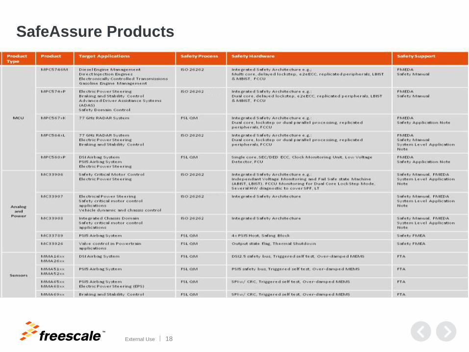
SafeAssure Products
To view the latest SafeAssure product table visit www.freescale.com/SafeAssure
TM
External Use 19
Agenda
• Functional Safety at Freescale
• Functional Safety and Microcontrollers
• MCU Safety Context and Safety Concepts
• Dynamic FMEDA
• Safety Manual
TM
External Use 20
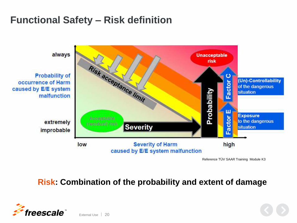
Functional Safety – Risk definition
Reference TÜV SAAR Training Module K3
Risk: Combination of the probability and extent of damage
TM
External Use 21
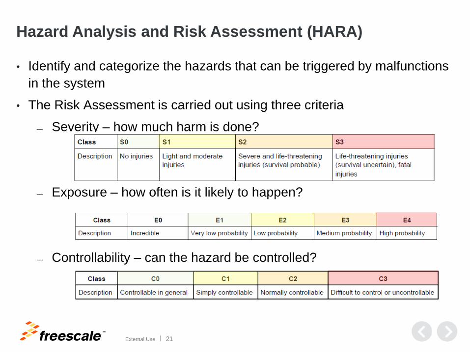
Hazard Analysis and Risk Assessment (HARA)
• Identify and categorize the hazards that can be triggered by malfunctions
in the system
• The Risk Assessment is carried out using three criteria
Severity – how much harm is done?
Exposure – how often is it likely to happen?
Controllability – can the hazard be controlled?
TM
External Use 22
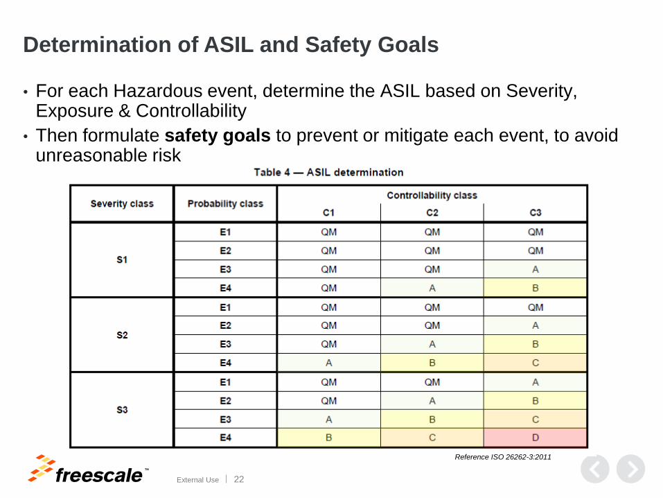
Determination of ASIL and Safety Goals
• For each Hazardous event, determine the ASIL based on Severity, Exposure & Controllability
• Then formulate safety goals to prevent or mitigate each event, to avoid unreasonable risk
Reference ISO 26262-3:2011
TM
External Use 23
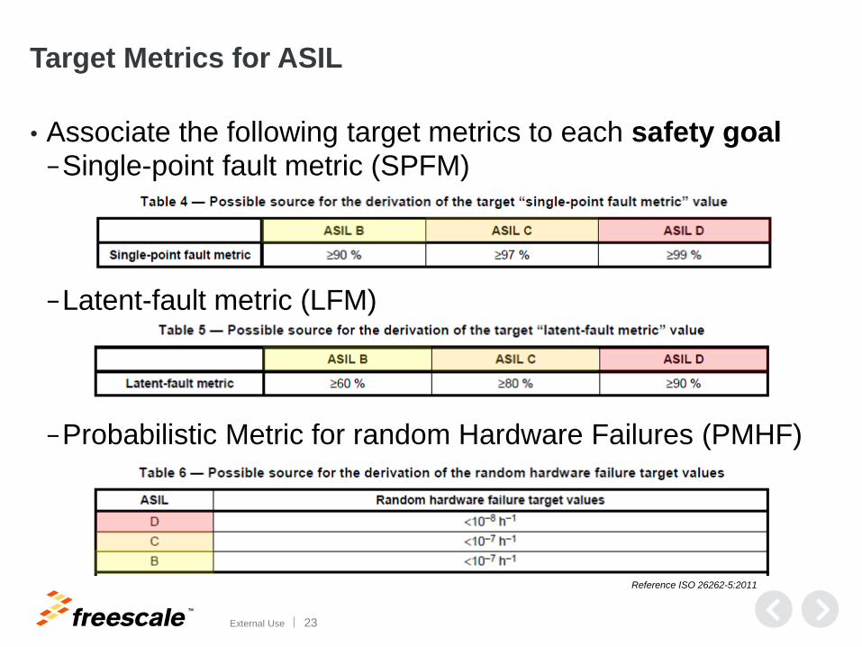
Target Metrics for ASIL
• Associate the following target metrics to each safety goal −Single-point fault metric (SPFM)
−Latent-fault metric (LFM)
−Probabilistic Metric for random Hardware Failures (PMHF)
Reference ISO 26262-5:2011
TM
External Use 24
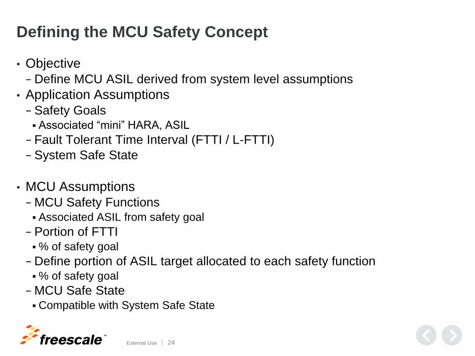
Defining the MCU Safety Concept
• Objective
− Define MCU ASIL derived from system level assumptions
• Application Assumptions − Safety Goals Associated “mini” HARA, ASIL
− Fault Tolerant Time Interval (FTTI / L-FTTI)
− System Safe State
• MCU Assumptions
− MCU Safety Functions Associated ASIL from safety goal
− Portion of FTTI % of safety goal
− Define portion of ASIL target allocated to each safety function % of safety goal
− MCU Safe State Compatible with System Safe State
TM
External Use 25
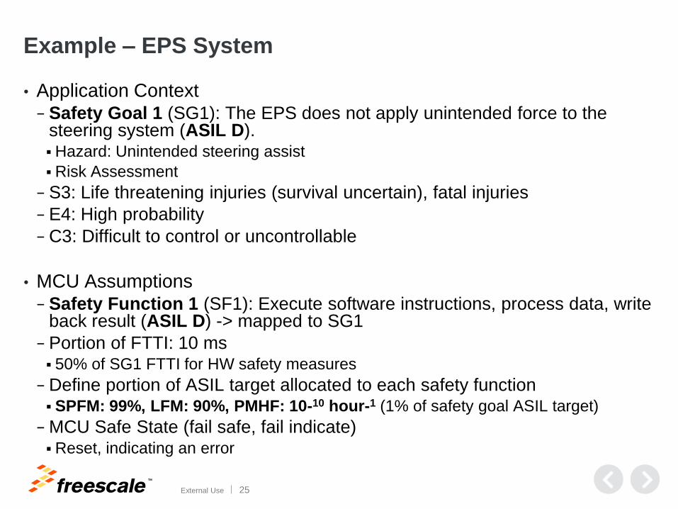
Example – EPS System
• Application Context
− Safety Goal 1 (SG1): The EPS does not apply unintended force to the steering system (ASIL D). Hazard: Unintended steering assist
Risk Assessment
− S3: Life threatening injuries (survival uncertain), fatal injuries
− E4: High probability
− C3: Difficult to control or uncontrollable
• MCU Assumptions
− Safety Function 1 (SF1): Execute software instructions, process data, write back result (ASIL D) -> mapped to SG1
− Portion of FTTI: 10 ms 50% of SG1 FTTI for HW safety measures
− Define portion of ASIL target allocated to each safety function SPFM: 99%, LFM: 90%, PMHF: 10-10 hour-1 (1% of safety goal ASIL target)
− MCU Safe State (fail safe, fail indicate) Reset, indicating an error
TM
External Use 26
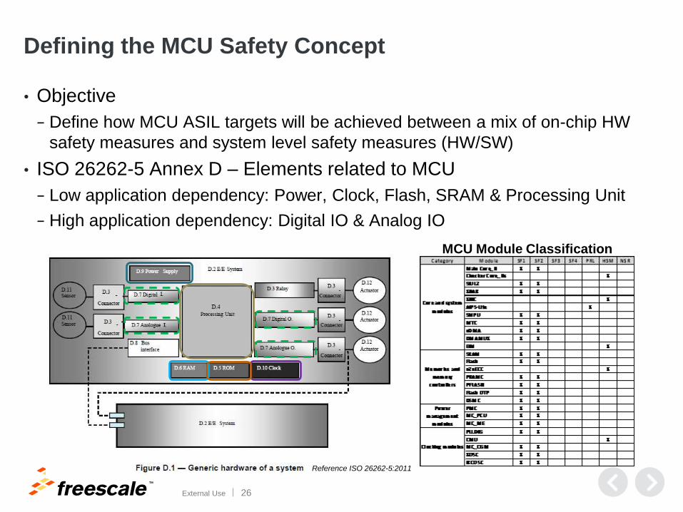
Defining the MCU Safety Concept
• Objective
− Define how MCU ASIL targets will be achieved between a mix of on-chip HW
safety measures and system level safety measures (HW/SW)
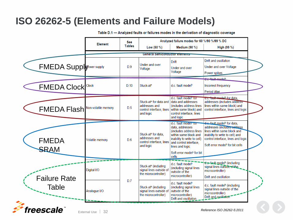
• ISO 26262-5 Annex D – Elements related to MCU
− Low application dependency: Power, Clock, Flash, SRAM & Processing Unit
− High application dependency: Digital IO & Analog IO
Reference ISO 26262-5:2011
MCU Module Classification
TM
External Use 27
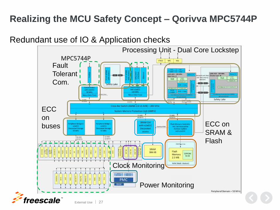
Realizing the MCU Safety Concept – Qorivva MPC5744P
Redundant use of IO & Application checks
Power Monitoring
Clock Monitoring
ECC on
SRAM &
Flash
Processing Unit - Dual Core Lockstep
ECC
on
buses
Fault
Tolerant
Com.
TM
External Use 28
Agenda
• Functional Safety at Freescale
• Functional Safety and Microcontrollers
• MCU Safety Context and Safety Concepts
• Dynamic FMEDA
• Safety Manual
TM
External Use 29
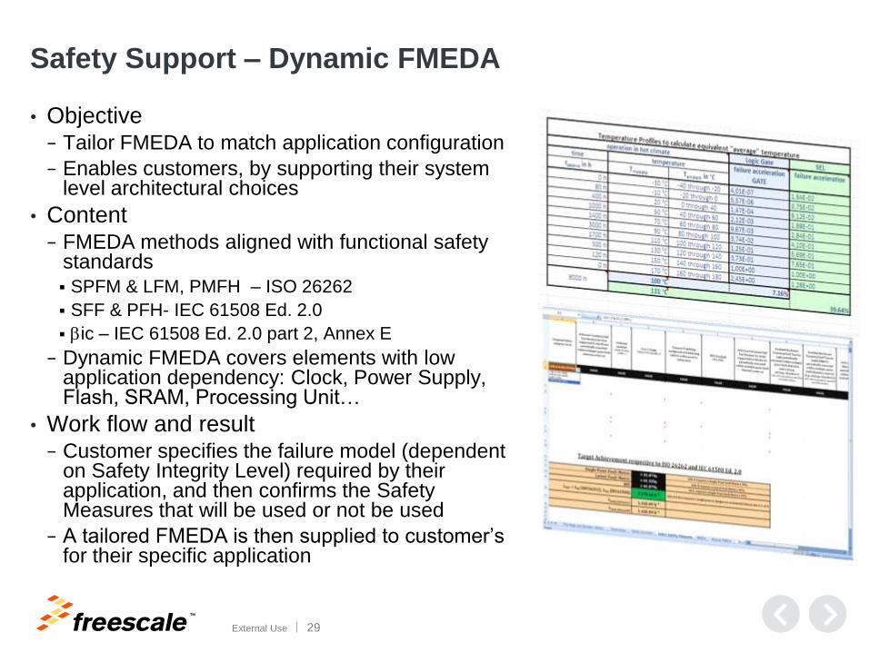
Safety Support – Dynamic FMEDA
• Objective − Tailor FMEDA to match application configuration
− Enables customers, by supporting their system level architectural choices
• Content − FMEDA methods aligned with functional safety
standards SPFM & LFM, PMFH – ISO 26262
SFF & PFH- IEC 61508 Ed. 2.0
bic – IEC 61508 Ed. 2.0 part 2, Annex E
− Dynamic FMEDA covers elements with low application dependency: Clock, Power Supply, Flash, SRAM, Processing Unit…
• Work flow and result − Customer specifies the failure model (dependent
on Safety Integrity Level) required by their application, and then confirms the Safety Measures that will be used or not be used
− A tailored FMEDA is then supplied to customer’s for their specific application
TM
External Use 30
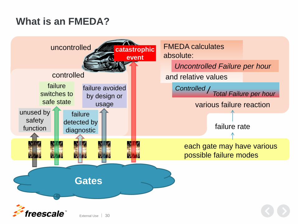
What is an FMEDA?
controlled
Gates
each gate may have various
possible failure modes
unused by
safety
function
failure
switches to
safe state
failure
detected by
diagnostic
failure avoided
by design or
usage
failure rate
various failure reaction
catastrophic
event
uncontrolled FMEDA calculates
absolute:
and relative values
Uncontrolled Failure per hour
Controlled / Total Failure per hour
TM
External Use 31
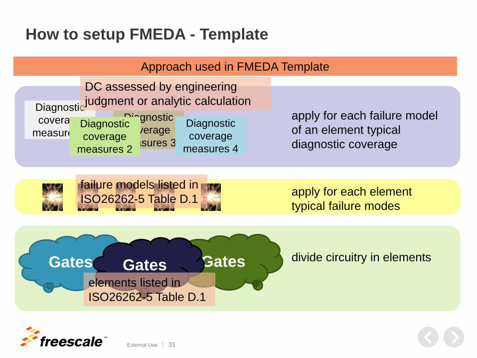
How to setup FMEDA - Template
Gates
apply for each element
typical failure modes
divide circuitry in elements Gates Gates
Diagnostic
coverage
measures 1
Diagnostic
coverage
measures 3
Diagnostic
coverage
measures 4
Diagnostic
coverage
measures 2
apply for each failure model
of an element typical
diagnostic coverage
elements listed in
ISO26262-5 Table D.1
failure models listed in
ISO26262-5 Table D.1
DC assessed by engineering
judgment or analytic calculation
Approach used in FMEDA Template
TM
External Use 32
ISO 26262-5 (Elements and Failure Models)
FMEDA Supply
FMEDA Clock
FMEDA Flash
FMEDA
SRAM
Failure Rate
Table
Reference ISO 26262-5:2011
TM
External Use 33
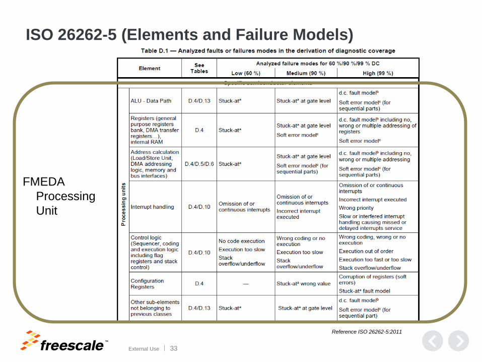
ISO 26262-5 (Elements and Failure Models)
FMEDA
Processing
Unit
Reference ISO 26262-5:2011
TM
External Use 34
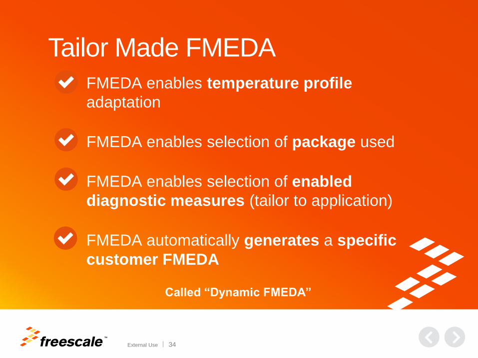
Tailor Made FMEDA
FMEDA enables temperature profile
adaptation
FMEDA enables selection of package used
FMEDA enables selection of enabled
diagnostic measures (tailor to application)
FMEDA automatically generates a specific
customer FMEDA
Called “Dynamic FMEDA”
TM
External Use 35
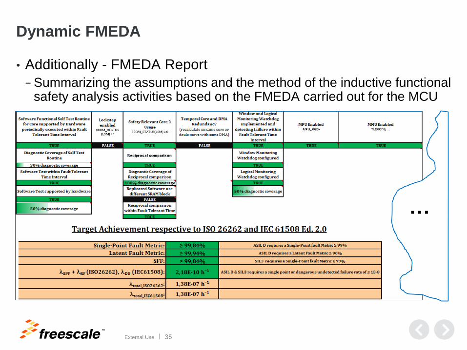
Dynamic FMEDA
• Additionally - FMEDA Report
− Summarizing the assumptions and the method of the inductive functional safety analysis activities based on the FMEDA carried out for the MCU
…
TM
External Use 36
Agenda
• Functional Safety at Freescale
• Functional Safety and Microcontrollers
• MCU Safety Context and Safety Concepts
• Dynamic FMEDA
• Safety Manual
TM
External Use 37
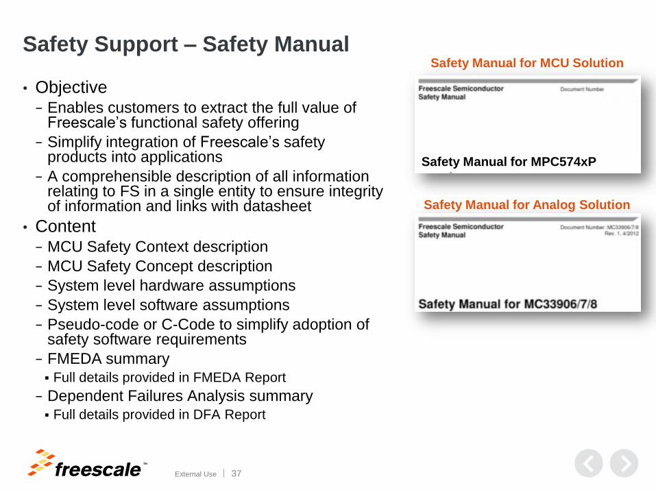
Safety Support – Safety Manual
Safety Manual for Analog Solution
Safety Manual for MCU Solution
Safety Manual for MPC574xP
• Objective − Enables customers to extract the full value of
Freescale’s functional safety offering
− Simplify integration of Freescale’s safety products into applications
− A comprehensible description of all information relating to FS in a single entity to ensure integrity of information and links with datasheet
• Content − MCU Safety Context description
− MCU Safety Concept description
− System level hardware assumptions
− System level software assumptions
− Pseudo-code or C-Code to simplify adoption of safety software requirements
− FMEDA summary Full details provided in FMEDA Report
− Dependent Failures Analysis summary Full details provided in DFA Report
TM
External Use 38
Safety Manual: Structure (1)
• Preface & General Information
− Safe states, Fault tolerant time interval
• Functional Safety Concept
− Customer should understand the safety concept of the device
(what is implemented and how does it work together)
• Hardware Requirements on System Level
− Description of all required (and optional) functions by external hardware
to achieve the safety goal(s) on system level
• Software Requirements on System Level
− Description of necessary or recommended sw mechanisms for each
module
− For each relevant module
Initial checks and configurations
Runtime checks
TM
External Use 39
Safety Manual: Structure (2)
• Failure Rates and FMEDA
− Short introduction and link to FMEDA
• Dependent Failure Analysis (qualitative)
− bic – IEC 61508 Ed. 2.0 part 2, Annex E: Analysis of dependent failures
− Countermeasures against common cause failures on chip level
− Restrictions caused by countermeasures (e.g. peripheral usage)
− Confidence-building measure
• Code-examples / Pseudocode
− Give a more rigorous description of the SW interactions
− Code fragments and examples (not intended for direct use)
− Enable customer to develop safety SW as intended
TM
External Use 40
Safety Specific Usage Considerations (1)
• Assumption:
− An assumption being relevant for functional safety in the specific application under consideration. It is assumed that the user fulfills an assumption in his design.
• Assumption under certain preconditions:
− An assumption being relevant under certain preconditions.
• Recommendation:
− A recommendation is either a proposal for the implementation of a requirement, or a reasonable mechanism which is recommended to be applied if there is no requirement in place. The user has the choice whether or not to follow the recommendation.
• Rationale:
− The motivation for a specific requirement and/or recommendation.
• Implementation hint:
− Specific hints on the implementation of a requirement and/or recommendation. The user has the choice whether or not to follow it.
TM
External Use 41
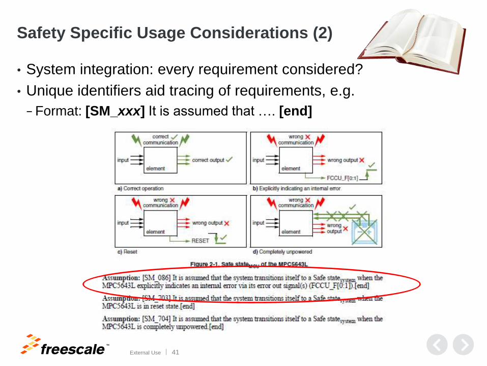
Safety Specific Usage Considerations (2)
• System integration: every requirement considered?
• Unique identifiers aid tracing of requirements, e.g.
− Format: [SM_xxx] It is assumed that …. [end]
TM
External Use 42
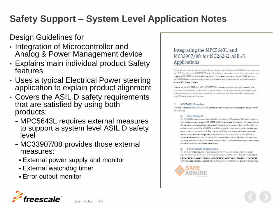
Safety Support – System Level Application Notes
Design Guidelines for
• Integration of Microcontroller and Analog & Power Management device
• Explains main individual product Safety features
• Uses a typical Electrical Power steering application to explain product alignment
• Covers the ASIL D safety requirements that are satisfied by using both products: − MPC5643L requires external measures
to support a system level ASIL D safety level
− MC33907/08 provides those external measures: External power supply and monitor
External watchdog timer
Error output monitor
TM
External Use 43
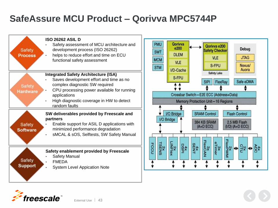
SafeAssure MCU Product – Qorivva MPC5744P
ISO 26262 ASIL D
• Safety assessment of MCU architecture and
development process (ISO 26262)
• helps to reduce effort and time on ECU
functional safety assessment
Integrated Safety Architecture (ISA)
• Saves development effort and time as no
complex diagnostic SW required
• CPU processing power available for running
applications
• High diagnostic coverage in HW to detect
random faults
SW deliverables provided by Freescale and
partners
• Enable support for ASIL D applications with
minimized performance degradation
• sMCAL & sOS, Selftests, SW Safety Manual
Safety enablement provided by Freescale
• Safety Manual
• FMEDA
• System Level Appication Note

TM
External Use 44
Supporting Material for Functional Safety
• SafeAssure @ www.freescale.com/SafeAssure
• Certification Package under NDA
• App-Notes, White Papers, Articles
• On-demand Training
TM
© 2014 Freescale Semiconductor, Inc. | External Use
www.Freescale.com