Embed Size (px)
Citation preview
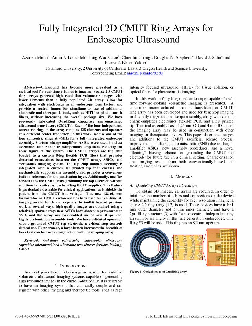
Fully Integrated 2D CMUT Ring Arrays for Endoscopic Ultrasound
Azadeh Moini1, Amin Nikoozadeh1, Jung Woo Choe1, Chienliu Chang1, Douglas N. Stephens2, David J. Sahn3 and Pierre T. Khuri-Yakub1
1 Stanford University, 2 University of California, Davis, 3 Oregon Health and Science University. Corresponding Email: [email protected]
Abstract—Ultrasound has become more prevalent as a medical tool for real-time volumetric imaging. Sparse 2D CMUT ring arrays generate high resolution volumetric images with fewer elements than a fully populated 2D array, allow for integration with electronics in an endoscope form factor, and provide a central lumen for simultaneous use of additional diagnostic and therapeutic tools, such as HIFU or photoacoustic fibers, without increasing the overall package size. We have previously fabricated QuadRing capacitive micromachined ultrasound transducers (CMUTs). Each of the four independent, concentric rings in the array contains 128 elements and operates at a different center frequency. In this work, we use one of the four concentric rings at 4MHz for a fully integrated endoscope assembly. Custom charge-amplifier ASICs were used in these assemblies rather than transimpedance amplifiers, reducing the noise figure of the system. The CMUT arrays are flip chip bonded to a custom 8-leg flexible PCB (flex) that provides electrical connections between the CMUT array, ASICs, and Verasonics imaging system. The flip chip bonded assembly is integrated with a custom 3D printed tip that encases and mechanically supports the assembly, and provides a convenient built-in reference for the passivation layer. Additionally, one flex version flips the CMUT bias, grounding the top electrode without additional circuitry by level-shifting the IC supplies. This feature is particularly desirable for clinical applications, as it shields the patient from the CMUT bias voltage. This new 128-element forward-facing CMUT endoscope has been used for real-time 3D imaging on the bench and expands the toolkit beyond previous work in several ways: high quality images are obtained using a relatively sparse array; new ASICs have shown improvements in SNR; and the array size has enabled use of new 3D-printed, highly customizable assembly tools. We have validated operation with a grounded CMUT top electrode, a critical step towards clinical use. Furthermore, a large lumen increases the breadth of tools that can be used in conjunction with the imaging array.
Keywords—real-time; volumetric; endoscopic; ultrasound capacitive micromachined ultrasonic transducer; forward-looking; CMUT
I. INTRODUCTION
In recent years there has been a growing need for real-time volumetric ultrasound imaging systems capable of generating high resolution images in the clinic. Additionally, it is desirable to have an imaging system that can easily couple and co-register with other imaging and therapeutic tools, such as high
intensity focused ultrasound (HIFU) for tissue ablation, or optical fibers for photoacoustic imaging.
In this work, a fully integrated endoscope capable of real-time forward-looking volumetric imaging is presented. A capacitive micromachined ultrasonic transducer, or CMUT, ring array has been developed and used for benchtop imaging in this fully integrated endoscope assembly, along with custom charge-amplifier electronics, flexible PCB, and a 3D printed tip. The final assembly has a 12.5 mm OD and 4 mm ID so that the imaging array may be used in conjunction with other imaging or therapeutic devices. This paper describes changes and additions to the CMUT sacrificial release process, improvements to the signal to noise ratio (SNR) due to charge-amplifier ASICs, new assembly procedures, and a novel “floating” biasing scheme for grounding the CMUT top electrode for future use in a clinical setting. Characterization and imaging results from both conventionally-biased and floating assemblies are shown.
II. METHODS
A. QuadRing CMUT Array Fabrication
To obtain 3D images, 2D arrays are required. In order to minimize the number of cables and connections on the device while maintaining the capability for high resolution imaging, a sparse 2D ring array [1,2] is used. These devices have a 10.1 mm outer diameter and 5 mm inner diameter, and have a QuadRing structure [3] with four concentric, independent ring arrays. For simplicity in the first generation endoscopes, only Ring #3 will be used. This ring has an 8.5 mm aperture.
Figure 1. Optical image of QuadRing array.
978-1-4673-9897-8/16/$31.00 ©2016 IEEE 2016 IEEE International Ultrasonics Symposium Proceedings
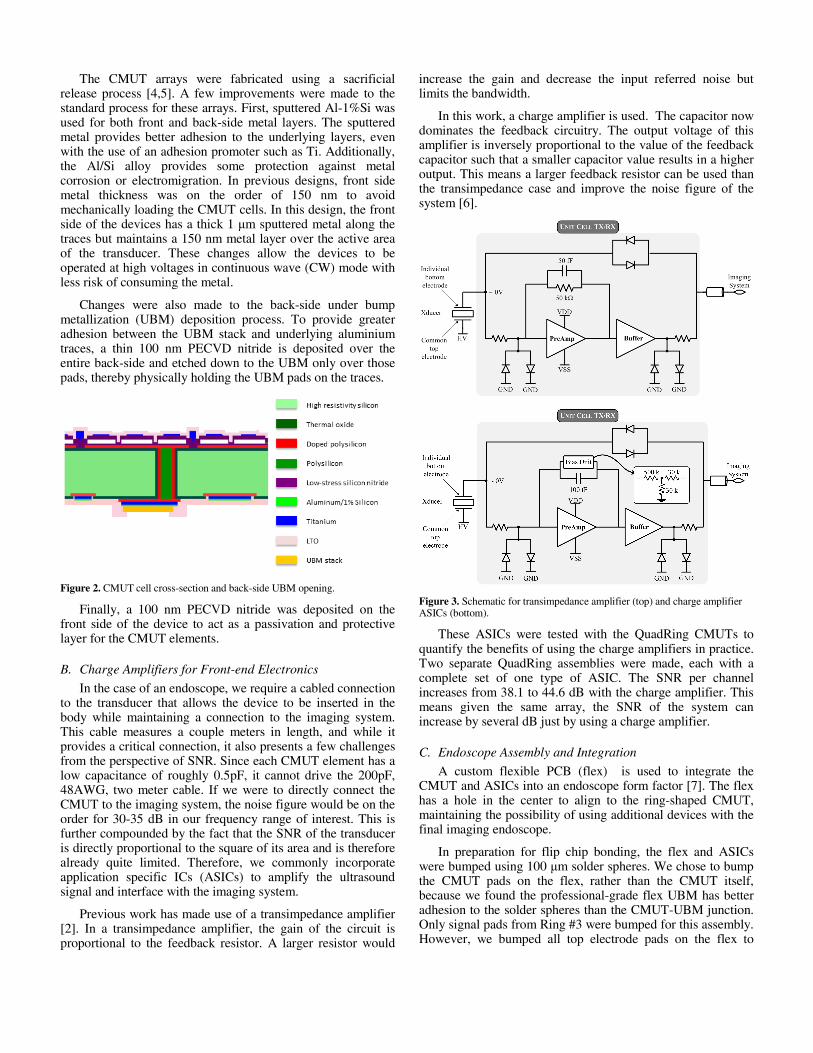
The CMUT arrays were fabricated using a sacrificial release process [4,5]. A few improvements were made to the standard process for these arrays. First, sputtered Al-1%Si was used for both front and back-side metal layers. The sputtered metal provides better adhesion to the underlying layers, even with the use of an adhesion promoter such as Ti. Additionally, the Al/Si alloy provides some protection against metal corrosion or electromigration. In previous designs, front side metal thickness was on the order of 150 nm to avoid mechanically loading the CMUT cells. In this design, the front side of the devices has a thick 1 μm sputtered metal along the traces but maintains a 150 nm metal layer over the active area of the transducer. These changes allow the devices to be operated at high voltages in continuous wave (CW) mode with less risk of consuming the metal.
Changes were also made to the back-side under bump metallization (UBM) deposition process. To provide greater adhesion between the UBM stack and underlying aluminium traces, a thin 100 nm PECVD nitride is deposited over the entire back-side and etched down to the UBM only over those pads, thereby physically holding the UBM pads on the traces.
Figure 2. CMUT cell cross-section and back-side UBM opening.
Finally, a 100 nm PECVD nitride was deposited on the front side of the device to act as a passivation and protective layer for the CMUT elements.
B. Charge Amplifiers for Front-end Electronics
In the case of an endoscope, we require a cabled connection to the transducer that allows the device to be inserted in the body while maintaining a connection to the imaging system. This cable measures a couple meters in length, and while it provides a critical connection, it also presents a few challenges from the perspective of SNR. Since each CMUT element has a low capacitance of roughly 0.5pF, it cannot drive the 200pF, 48AWG, two meter cable. If we were to directly connect the CMUT to the imaging system, the noise figure would be on the order for 30-35 dB in our frequency range of interest. This is further compounded by the fact that the SNR of the transducer is directly proportional to the square of its area and is therefore already quite limited. Therefore, we commonly incorporate application specific ICs (ASICs) to amplify the ultrasound signal and interface with the imaging system.
Previous work has made use of a transimpedance amplifier [2]. In a transimpedance amplifier, the gain of the circuit is proportional to the feedback resistor. A larger resistor would
increase the gain and decrease the input referred noise but limits the bandwidth.
In this work, a charge amplifier is used. The capacitor now dominates the feedback circuitry. The output voltage of this amplifier is inversely proportional to the value of the feedback capacitor such that a smaller capacitor value results in a higher output. This means a larger feedback resistor can be used than the transimpedance case and improve the noise figure of the system [6].
Figure 3. Schematic for transimpedance amplifier (top) and charge amplifier ASICs (bottom).
These ASICs were tested with the QuadRing CMUTs to quantify the benefits of using the charge amplifiers in practice. Two separate QuadRing assemblies were made, each with a complete set of one type of ASIC. The SNR per channel increases from 38.1 to 44.6 dB with the charge amplifier. This means given the same array, the SNR of the system can increase by several dB just by using a charge amplifier.
C. Endoscope Assembly and Integration
A custom flexible PCB (flex) is used to integrate the CMUT and ASICs into an endoscope form factor [7]. The flex has a hole in the center to align to the ring-shaped CMUT, maintaining the possibility of using additional devices with the final imaging endoscope.
In preparation for flip chip bonding, the flex and ASICs were bumped using 100 μm solder spheres. We chose to bump the CMUT pads on the flex, rather than the CMUT itself, because we found the professional-grade flex UBM has better adhesion to the solder spheres than the CMUT-UBM junction. Only signal pads from Ring #3 were bumped for this assembly. However, we bumped all top electrode pads on the flex to
provide more mechanical support to the wide CMUT during flip chip bonding and reflow. On the ASIC side, ASIC itself is bumped. A custom fixture is used in the flip chip bonding process to ensure uniform heating across the solder balls.
Figure 4. Optical image of flexible PCB. Back side (top left), bumped side (top right, bottom left) and flip chip bonding fixture (bottom right).
For final integration with the catheter shaft, the eight legs of the flex assembly must be folded down and supported by some structure. This structure must provide a protective covering for the ASICs, allow the device to be forward facing, and provide a built-in reference for the passivation layer.
A 3D printed tip has been designed and manufactured to incorporate all these needs. The tip has a 12.5 mm outer diameter, just slightly larger than the 10.1 mm transducer array. There are eight slits in the tip through which the eight legs of the flex are passed. The back side of the CMUT array rests on the center octagon. The outer cylinder of the tip protects the ASICs from damage during device use. Additionally, the tips are designed to have a lip which extends slightly beyond the CMUT face to provide a reference for the passivation layer. The tips have a 4 mm diameter hole through their center to maintain the center lumen of the endoscope.
Bypass capacitors are adhered to the flex using conductive epoxy to reduce noise on the power supplies. The lip of the 3D printed tip was used as a reference for the Sylgard 160 passivation layer.
Figure 5. 3D printed endoscope tip.
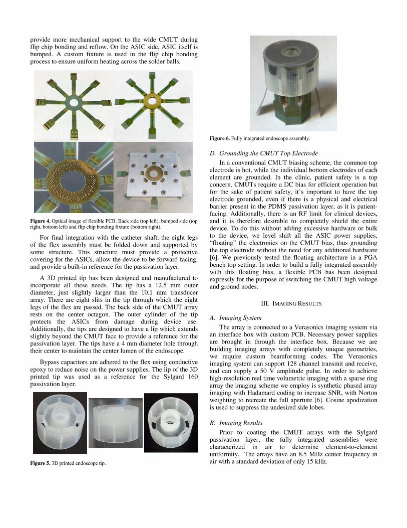
Figure 6. Fully integrated endoscope assembly.
D. Grounding the CMUT Top Electrode
In a conventional CMUT biasing scheme, the common top electrode is hot, while the individual bottom electrodes of each element are grounded. In the clinic, patient safety is a top concern. CMUTs require a DC bias for efficient operation but for the sake of patient safety, it’s important to have the top electrode grounded, even if there is a physical and electrical barrier present in the PDMS passivation layer, as it is patient-facing. Additionally, there is an RF limit for clinical devices, and it is therefore desirable to completely shield the entire device. To do this without adding excessive hardware or bulk to the device, we level shift all the ASIC power supplies, “floating” the electronics on the CMUT bias, thus grounding the top electrode without the need for any additional hardware [6]. We previously tested the floating architecture in a PGA bench top setting. In order to build a fully integrated assembly with this floating bias, a flexible PCB has been designed expressly for the purpose of switching the CMUT high voltage and ground nodes.
III. IMAGING RESULTS
A. Imaging System
The array is connected to a Verasonics imaging system via an interface box with custom PCB. Necessary power supplies are brought in through the interface box. Because we are building imaging arrays with completely unique geometries, we require custom beamforming codes. The Verasonics imaging system can support 128 channel transmit and receive, and can supply a 50 V amplitude pulse. In order to achieve high-resolution real time volumetric imaging with a sparse ring array the imaging scheme we employ is synthetic phased array imaging with Hadamard coding to increase SNR, with Norton weighting to recreate the full aperture [6]. Cosine apodization is used to suppress the undesired side lobes.
B. Imaging Results
Prior to coating the CMUT arrays with the Sylgard passivation layer, the fully integrated assemblies were characterized in air to determine element-to-element uniformity. The arrays have an 8.5 MHz center frequency in air with a standard deviation of only 15 kHz.
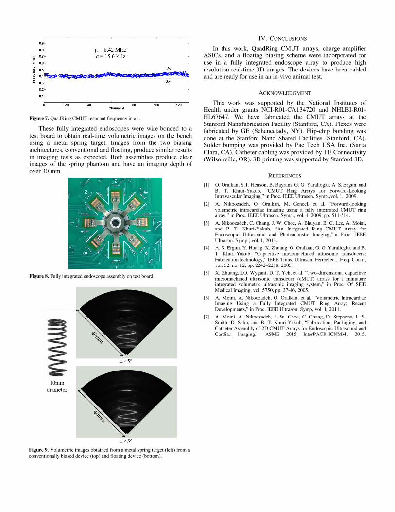
Figure 7. QuadRing CMUT resonant frequency in air.
These fully integrated endoscopes were wire-bonded to a test board to obtain real-time volumetric images on the bench using a metal spring target. Images from the two biasing architectures, conventional and floating, produce similar results in imaging tests as expected. Both assemblies produce clear images of the spring phantom and have an imaging depth of over 30 mm.
Figure 8. Fully integrated endoscope assembly on test board.
IV. CONCLUSIONS
In this work, QuadRing CMUT arrays, charge amplifier ASICs, and a floating biasing scheme were incorporated for use in a fully integrated endoscope array to produce high resolution real-time 3D images. The devices have been cabled and are ready for use in an in-vivo animal test.
ACKNOWLEDGMENT
This work was supported by the National Institutes of Health under grants NCI-R01-CA134720 and NHLBI-R01-HL67647. We have fabricated the CMUT arrays at the Stanford Nanofabrication Facility (Stanford, CA). Flexes were fabricated by GE (Schenectady, NY). Flip-chip bonding was done at the Stanford Nano Shared Facilities (Stanford, CA). Solder bumping was provided by Pac Tech USA Inc. (Santa Clara, CA). Catheter cabling was provided by TE Connectivity (Wilsonville, OR). 3D printing was supported by Stanford 3D.
REFERENCES [1] O. Oralkan, S.T. Henson, B. Bayram, G. G. Yaralioglu, A. S. Ergun, and
B. T. Khrui-Yakub, “CMUT Ring Arrays for Forward-Looking Intravascular Imaging,” in Proc. IEEE Ultrason. Symp.,vol. 1, 2009.
[2] A. Nikoozadeh, O. Oralkan, M. Gencel, et al, “Forward-looking volumetric intracardiac imaging using a fully integrated CMUT ring array,” in Proc. IEEE Ultrason. Symp., vol. 1, 2009, pp. 511-514.
[3] A. Nikoozadeh, C. Chang, J. W. Choe, A. Bhuyan, B. C. Lee, A. Moini, and P. T. Khuri-Yakub, “An Integrated Ring CMUT Array for Endoscopic Ultrasound and Photoacoustic Imaging,”in Proc. IEEE Ultrason. Symp., vol. 1, 2013.
[4] A. S. Ergun, Y. Huang, X. Zhuang, O. Oralkan, G. G. Yaralioglu, and B. T. Khuri-Yakub, “Capacitive micromachined ultrasonic transducers: Fabrication technology,” IEEE Trans. Ultrason. Ferroelect., Freq. Contr., vol. 52, no. 12, pp. 2242–2258, 2005.
[5] X. Zhuang, I.O. Wygant, D. T. Yeh, et al, “Two-dimensional capacitive micromachined ultrasonic transdcuer (cMUT) arrays for a miniature integrated volumetric ultrasonic imaging system,” in Proc. Of SPIE Medical Imaging, vol. 5750, pp. 37-46, 2005.
[6] A. Moini, A. Nikoozadeh, O. Oralkan, et al, “Volumetric Intracardiac Imaging Using a Fully Integrated CMUT Ring Array: Recent Developments,” in Proc. IEEE Ultrason. Symp, vol. 1, 2011.
[7] A. Moini, A. Nikoozadeh, J. W. Choe, C. Chang, D. Stephens, L. S. Smith, D. Sahn, and B. T. Khuri-Yakub, “Fabrication, Packaging, and Catheter Assembly of 2D CMUT Arrays for Endoscopic Ultrasound and Cardiac Imaging,” ASME 2015 InterPACK-ICNMM, 2015.
Figure 9. Volumetric images obtained from a metal spring target (left) from a conventionally biased device (top) and floating device (bottom).