Embed Size (px)
Citation preview

Service Manual
Fuller Heavy Duty TransmissionsTRSM0660October 2007
RTLO-14613BRTLOF-14613B


TABLE OF CONTENTSFOREWORD . . . . . . . . . . . . .MODEL DESIGNATIONS ANDLUBRICATION . . . . . . . . . . . .OPERATION . . . . . . . . . . . . .POWER FLOW . . . . . . . . . . .TIMING . . . . . . . . . . . . . . . . . .
. . . . . . . . ...* . . . . . . . . . . . . . . . . . . . . . . . . . . . . . . . . . . . . . . .
SPECIFICATIONS . . . . . . . . . . . . . . . . . . . . . . . . . . . . . . . . . . .. . . . . . . . . . . . . . . . . . . . . . . . . . . . . . . . . . . . . . . . . . . . . . . . . . .
. . . . . . . . . . . . . . . . . . . . . . . . . . . . . . . . . . . . . . . . . . . . .
. . . . . . . . . . . . . . . . . . . . . . . . . . . . . . . . . . . . . . . . . . . . . . . . . . .
. . . . . . . . . . . . ■ ✎✎✌✎ ✎ ✎ ✎ ✎ ✎ ✎ ✎ ✎ ✎ ✎ ✎ ✎ ✎ ✎ ✎ ✎ ✎ ✎ ✎ ✎ ✎ ✎ ✎ ✎ ✎ ✎ ✎ ✎ ✎ ✎ ✎ ✎ ✎
TORQUE RECOMMENDATIONS . . . . . . . . . . . . . . . . . . . . . . . . . . . . . . . . . . . . . . . . . . . . . . . .TOOL REFERENCE . . . . . . . . . . . . . . . . . . . . . . . . . . . . . . . . . . . . . . . . . . . . . . . . . . . . . . . . . . .PREVENTIVE MAINTENANCE . . . . . . . . . . . . . . . . . . . . . . . . . . . . . . . . . . . . . . . . . . . . . . . . . .PRECAUTIONS
DISASSEMBLY . . . . . . . . . . . . . . . . . . . . . . . . . . . . . . . . . . . . . . . . . . . . . . . . . . . . . . . . . . .INSPECTION . . . . . . . . . . . . . . . . . . . . . . . . . . . . . . . . . . . . . . . . . . . . . . . . . . . . . . . . . . . .REASSEMBLY .. mm. m.. . m . . . . . . . . . . . . . . . . . . . . . . . . . . .
CHANGING INPUT SHAFT . . . . . . . . . . . . . . . . . . . . . . . . . . . . . . . . . . . . . . . . . . . . . . . . . . . . .AIR SYSTEM
RANGE SHIFT AIR SYSTEM . . . . . . . . . . . . . . . . . . . . . . . . . . . . . . . . . . . . . . . . . . . . . . . .SPLITTER SHIFT AIR SYSTEM . . . . . . . . . . . . . . . . . . . . . . . . . . . . . . . . . . . . . . . . . . . . . .
AIR SYSTEM SCHEMATICS . . . . . . . . . . . . . . . . . . . . . . . . . . . . . . . . . . . . . . . . . . . . . . . . . . . .DISASSEMBLY SHIFTING CONTROLS . . . . . . . . . . . . . . . . . . . . . . . . . . . . . . . . . . . . . . . . . . .DISASSEMBLY GEAR SHIFT LEVER ASSEMBLY . . . . . . . . . . . . . . . . . . . . . . . . . . . . . . . . . .REASSEMBLY GEAR SHIFT LEVER ASSEMBLY . . . . . . . . . . . . . . . . . . . . . . . . . . . . . . . . . . .DISASSEMBLY AND REASSEMBLY SHIFT BAR HOUSING . . . . . . . . . ■ . . . . . . . . . . . . . . . . .REMOVAL – OUTPUT YOKE, AUXILIARY SECTION AND CLUTCH HOUSING . . . . . . . . . . . .DISASSEMBLY – AUXILIARY SECTION . . . . . . . . . . . . . . . . . . . . . . . . . . . . . . . . . . . . . . . . . .REASSEMBLY -AUXILIARY SECTION . . . . . . . . . . . . . . . . . . . . . . . . . . . . . . . . . . . . . . . . . . .DISASSEMBLY – FRONT SECTION . . . . . . . . . . . . . . . . . . . . . . . . . . . . . . . . . . . . . . . . . . . . . .REASSEMBLY – FRONT SECTION . . . . . . . . . . . . . . . . . . . . . . . . . . . . . . . . . . . . . . . . . . . . . .INSTALLATION – CLUTCH HOUSING, AUXILIARY SECTION AND OUTPUT YOKE . . . . . . . .INSTALLATION – SHIFTING CONTROLS . . . . . . . . . . . . . . . . . . . . . . . . . . . . . . . . . . . . . . . . .SHIMMING CHART . . . . . . . . . . . . . . . . . . . . . . . . . . . . . . . . . . . . . . . . . . . . . . . . . . . . . . . . . . .
1

FOREWORDThis manual is designed to provide detailed information
necessary to service and repair the Fuller’ Transmissionslisted on the cover.
As outlined in the Table of Contents, the manual isdivided into 3 main sections:
a. Technical information and referenceb. Removal, disassembly, reassembly and
installationc. Options
The format of the manual is designed to be followed in itsentirety if complete disassembly and reassembly of thetransmission is necessary. But if only one component of thetransmission needs to be repaired, refer to the Table ofContents for the page numbers showing that component.For example, if you need to work on the Shifting Controls,you will find instructions for removal, disassembly andreassembly on page 32. Instructions for installation are on
page 116. Service Manuals, Illustrated Parts Lists, DriversInstructions, and other forms of product service informationfor these and other Fuller Transmissions are available uponrequest. A Technical Literature Order Form maybe found inthe back of this manual. You may also obtain ServiceBulletins, detailing information on product improvements,repair procedures and other service-related subjects bywriting to the following address:
EATON CORPORATIONTRANSMISSION DIVISIONTechnical Service DepartmentP.O. Box 4013Kalamazoo, Michigan 49003(61 6) 342-3344
Every effort has been made to ensure the accuracy of all information in this brochure. However, Eaton Transmission Divisionmakes no expressed or implied warranty or representation based on the enclosed information. Any errors or omissions maybe reported to Training and Publications, Eaton Transmission Division, PO. Box 4013, Kalamazoo, Ml 49003.
2

MODEL DESIGNATIONSAND SPECIFICATIONSNomenclature:
RTLO-14613
IMPORTANT: All Fuller Transmissions are identified bymodel and serial number. This information is stamped onthe transmission identification tag and affixed to the case.DO NOT REMOVE OR DESTROY THE TRANSMISSIONIDENTIFICATION TAG.
13-Speed Transmissions (On/Off Highway):Relative Speed 1 2 3
Gear Ratios: PTO Gear Length Weight Oil Cap.Model No
Spds.To Input R.P.M. In. Lbs. Pints
LO 1 St 2nd 3rd 4th 5th 6th 7th 8th Reverse Right Bottom (mm) (Kgs.) (Liters)
RTLO-14613 13 DIR 14.71 10.20 7.34 5.26 3.78 2.70 1.94 1.39 1.00 3.89/14.71 .696 .696 324 748 28(823.5) (339.3) (13.25)
OD 2.28 1.64 1.18 .85 3.29/12.45
CHART NOTES:
1. Lengths measured from face of clutch housing to front bottoming surface of companion flange or yoke.
2. Weight - Listed weights are with clutch housing* and include standard controls, which consist of gear shift lever housingand gear shift lever. Weight of standard controls is approximately 10 lbs. (4.5 kg.). All weights are approximate.
3. Oil Capacities are approximate, depending on inclination of engine and transmission. Always fill transmission with propergrade and type of lubricant to level of filler opening. See LUBRICATION.
*For information on available clutch housings refer to Publication FUL-140 – “Clutch Housing Chart”.
3

LUBRICATIONProperLubrication . . .
Fahrenheit(Celsius)Ambient
Temperature
the Key to longtransmission lifeProper lubrication procedures are the key to agood all-around maintenance program. If theoil is not doing its job, or if the oil level isignored, all the maintenance procedures in theworld are not going to keep the transmissionrunning or assure long transmission life.
Eaton® Fuller® Transmissions are designedso that the internal parts operate in a bath ofoil circulated by the motion of gears and shafts.
Thus, ail parts will be amply lubricated ifthese procedures are closely followed:
1. Maintain oil level. Inspect regularly.2. Change oil regularly.3. Use the correct grade and type of oil.4. Buy from a reputable dealer.
Lubrication Change and Inspection
Eaton® Roadranger ® CD50 Transmission Fluid
HIGHWAY USE—Heavy Duty and Mid-Range
First 3,000 to 5,000 miles Factory fill(4827 to 8045 Km) Inltlal drain
Every 10,000 miles Check fluid level(16090 Km) Check for leaks
Heavy Duty Highway Change Interval
Every 250,000 miles Change transmission(402336 Km) fluid,
Mid-Range Highway Change Interval
Every 100,000 miles (160,000 Km) Change transmissionor every 3 years whichever occurs first fluid.
I OFF-HIGHWAY USE
First 30 hours Factory fill Initial drain,
Every 40 hours Inspect fluid level Check for leaks
I Every 500 hours Change transmission fluid wheresevere dirt conditions exist.
I Every 1,000 hours Change transmission fluid(Normal off-highway use),
Heavy Duty Engine Lubricant orMineral Gear Lubricant
I HIGHWAY USE
I First 3,000 to 5,000 miles Factory fill(4827 to 8045 Km) Initial drain.
I Every 10,000 miles Inspect Iubricant level,(16090 Km) Check for leaks,
I Every 50,000 miles Change transmission(80450 Km) lubricant,
I OFF-HIGHWAY USE
First 30 hours Change transmission lubricant on new units
Every 40 hours Inspect Iubricant level Check for leaks
Every 500 hours Change transmission Iubricant wheresevere dirt conditions exist.
Every 1,000 hours Change transmission Iubricant(Normal off-highway use),
Change the oil filter when fluid or lubricant is changed.
Recommended Lubricants
GradeType (SAE)
Eaton® Roadranger®
CD50 TransmissionFluid 50 All
Heavy Duty Engine 011MI L-L-2104B C or D or 50 Above 10oF(-12oC.)API-SF or API-CD 40 Above 10oF(-12oC.)
(Previous API designations 30 Below 10oF(-12oC.)acceptable)
Mineral Gear 011 with rust 90 Above 10oF(-12oC.)and oxidation Inhibitor 80W Below 10oF(-12oC.)API-GL-1
The use of mild EP gear oil or multi-pur-pose gear oil is not recommended, but ifthese gear oils are used, be sure to adhere tothe following limitations:
Do not use mild EP gear oil or multi-pur-pose gear oil when operating temperatures areabove 230°F (110oC). Many of these gear oils,particularly 85W140, break down above 230°Fand coat seals, bearings and gears with de-posits that may cause premature failures. Ifthese deposits are observed (especially a coat-ing on seal areas causing oil leakage), changeto Eaton Roadranger CD50 transmission fluid,heavy duty engine oil or mineral gear oil toassure maximum component life and to main-tain your warranty with Eaton. (Also see“Operating Temperatures”.)
Additives and friction modifiers are not recom-mended for use in Eaton Fuller transmissions.
Proper Oil LevelMake sure oil is level with filler opening. Be-cause you can reach oil with your finger doesnot mean oil is at proper level. One inch of oillevel is about one gallon of oil.
Draining OilDrain transmission while oil is warm. To drainoil remove the drain plug at bottom of case.Clean the drain plug before re-installing.
RefillingClean case around filler plug and remove plugfrom side of case. Fill transmission to thelevel of the filler opening. If transmission hastwo filler openings, fill to level of both open-ings.
The exact amount of oil will depend on thetransmission inclination and model. Do notover fill—this will cause oil to be forced outof the transmission.
When adding oil, types and brands of oilshould not be mixed because of possible in-
4 compatibility.
, ... . . .

LUBRICATIONOperating Temperatures—With Eaton® Roadranger ®
CD50 Transmission FluidHeavy Duty Engine Oiland Mineral Oil
The transmission should not be operated con-sistently at temperatures above 250oF (120oC).However, intermittent operating temperaturesto 300oF (149oC) will not harm the transmis-sion. Operating temperatures above 250oFincrease the lubricant’s rate of oxidation andshorten its effective life. When the averageoperating temperature is above 250oF, thetransmission may require more frequent oilchanges or external cooling.
The following conditions in any combina-tion can cause operating temperatures of over250oF: (1) operating consistently at slowspeeds, (2) high ambient temperatures, (3) re-stricted air flow around transmission, (4) ex-haust system too close to transmission, (5)high horsepower, overdrive operation.
External oil coolers are available to reduceoperating temperatures when the above condi-tions are encountered.
Transmission Oil Coolers are:
Recommended— With engines of 350 H.P. and above
with overdrive transmissions
Required
— With engines 399 H.P. and above withoverdrive transmissions and GCW’Sover 90,000 lbs.
— With engines 399 H.P. and above and1400 Lbs.-Ft. or greater torque
— With engines 450 H.P. and above
— With EP or Multipurpose Gear OilMild EP gear oil and multipurpose gear oil arenot recommended when lubricant operatingtemperatures are above 230°F (110). In addi-tion, transmission oil coolers are not recom-mended with these gear oils since the oilcooler materials may be attacked by thesegear oils. The lower temperature limit and oilcooler restriction with these gear oils gener-ally limit their success to milder applications.
Proper Lubrication Levelsas Related to TransmissionInstallation AnglesIf the transmission operating angle is morethan 12 degrees, improper lubrication can oc-cur. The operating angle is the transmissionmounting angle in the chassis plus the per-cent of upgrade (expressed in degrees).
The chart below illustrates the safe percentof upgrade on which the transmission can beused with various chassis mounting angles.For example: if you have a 4 degree transmis-sion mounting angle, then 8 degrees (or 14percent of grade) is equal to the limit of 12degrees. If you have a O degree mountingangle, the transmission can be operated on a12 degree (21 percent) grade.
Anytime the transmission operating angle of12 degrees is exceeded for an extendedperiod of time the transmission should beequipped with an oil pump or cooler kit toinsure proper lubrication.
Note on the chart the effect low oil levelscan have on safe operating angles. Allowingthe oil level to fall 1/2” below the filler plughole reduces the degree of grade by approxi-mately 3 degrees (5.5 percent).
Proper Lubrication Levels are Essential!
Transmission Mounting AngleDotted line showing “2 Quarts Low” is forreference only. Not recommended.
5

OPERATION13-Speed Overdrive Models
Shift Lever Patterns and Shifting Controls
RTO (Overdrive) ModelsRTOX (Double-Overdrive) Models
With Splitter Control But”ton in “DIR.’’/REARWARDposition . . .Shift LO-1-2-3-4 in LOWRANGE.
Range shift . . .
And shift 5.6-7-8 in HIGHRANGE (Direct).
WHILE IN HIGH RANGEONLY . . .Ratios can be split bymoving Splitter ControlButton to the "O.D.”/FORWARD position togain OVERDRIVE 5-6-7-8.
Roadranger Valve(A-4900)
SPLITTER CONTROL BUTTON
6
. .—.

POWER FLOWThe transmission must efficiently transfer the engine’s power, in terms of torque, to the vehicle’s rear wheels.Knowledge of what takes place in the transmission during torque transfer is essential when troubleshootingand making repairs.
Front Section Power Flow(LO Range Direct)
1.
2.
3.
4.
5.
6.
Power (torque) from the vehicle’s engine is trans- 7.ferred to the transmission’s input shaft.Splines of input shaft engage internal splines in 8.hub of main drive gear.Torque is split between the two countershaftdrive gears. 9.Torque is delivered along both countershaft tomating countershaft gears of “engaged” main- 10.shaft gear. The following cross section views il-lustrate a 1st/5th speed gear engagement.Internal clutching teeth in hub of engaged main-shaft gear transfers torque to mainshaft throughsliding clutch.Mainshaft transfers torque directly to rear aux-iliary drive gear.
The rear auxiliary drive gear splits torque be-tween the two auxiliary countershaft drive gears.Torque is delivered along both auxiliary counter-shaft to the “engaged” reduction gear on outputshaft.Torque is transferred to output shaft through slid-ing clutch.Output shaft delivers torque to driveline.
LO RANGE DIRECT
Cut 8006C-11 /87
7

POWER FLOWAuxiliary Section Power Flow:HI
7.
RANGE DIRECTThe rear auxiliary drive gear transfers torque 8. Torque is delivered through theoutput shaft todirectly to the output shaft through –engaged” driveline as HI RANGE 5th gear.sliding clutch.
8

POWER FLOWAuxiliary Section Power Flow:HI
7.
8.
RANGE OVERDRIVEThe front auxiliary drive gear splits torque be- 9. Torque is transferred to output shaft through thetween the two auxiliary countershaft drive gears. sliding clutch.Torque is delivered along both auxiliary counter- 10. Output shaft delivers torque to driveline as HIs h a f t s t o m a t i n g c o u n t e r s h a f t g e a r s o f Range 5th gear OVERDRIVE.“engaged” rear auxiliary drive gear.
9

TIMINGTiming Procedures: All ModeIs
It is essential that both countershaft assemblies ofthe front and auxiliary sections are “timed. ” This as-sures proper tooth contact is made between main-shaft gears seeking to center on the mainshaftduring torque transfer and mating countershaft gearsthat distribute the load evenly. If not properly timed,serious damage to the transmission is likely to resultfrom unequal tooth contact causing the mainshaftgears to climb out of equilibrium.
Timing is a simple procedure of marking the appro-priate teeth of a gear set prior to installation andplacing them in proper mesh while in the transmis-sion. In the front section, it is necessary to time onlythe drive gear set. And depending on the model, onlythe LO range, deep reduction, or splitter gear set istimed in the auxiliary section.
Front SectionA. Marking countershaft drive gear teeth.
1. Prior to placing each countershaft assemblyinto case, clearly mark the tooth locateddirectly over the keyway of drive gear asshown. This tooth is stamped with an “O” toaid identification.
Tooth on Countershaftdirectly over Keywaymarked for timing
Cut 7300 H-11/86
B. Marking main drive gear teeth.1.
2.
Mark any two adjacent teeth on the main drivegear.Mark the two adjacent teeth located directlyopposite the first-set marked on the main drivegear. As shown below, there should be anequal number of unmarked gear teeth on eachside between the marked sets.
Drive gear teeth correct/ymarked for timing.
C. Meshing marked countershaft drive gear teethwith marked main drive gear teeth.(After placing the mainshaft assembly into case,the countershaft bearings are installed to com-plete installation of the countershaft assemblies.)1.
2.
When installing the bearings on left counter-shaft, mesh the marked tooth of countershaftdrive gear with either set or two marked teethon the main drive gear.Repeat the procedure when installing thebearings on right countershaft, making use ofthe remaining set of two marked teeth on themain drive gear to time assembly.
Countershaft gear teethmeshed with drive gear teethfor correct timing.
Cut 7300 F-1 1/86
Auxiliary SectionA. Timing the auxiliary countershaft and LO range
gear.1.
2.
3.
4.5.
6.
Mark any two adjacent teeth on “the LO rangegear of set to be timed. Then mark the two ad-jacent teeth located directly opposite the firstset marked as shown in Illustration B.Prior to placing each auxiliary countershaft as-sembly into housing, mark the tooth stampedwith an “O” on gear to mate with timed main-shaft gear as shown in Illustration A.Install the LO range gear on the out put shaftand into the auxiliary case.Seat the auxiliary countershaft bearings.Install the rear bearing cover and tighten torecommended torque.Place the auxiliary countershaft assembliesinto position and mesh the marked teeth of themating countershaft gears with the markedteeth of the LO range gear as shown in illustra-tion C.
Cut 7300 G-11/86
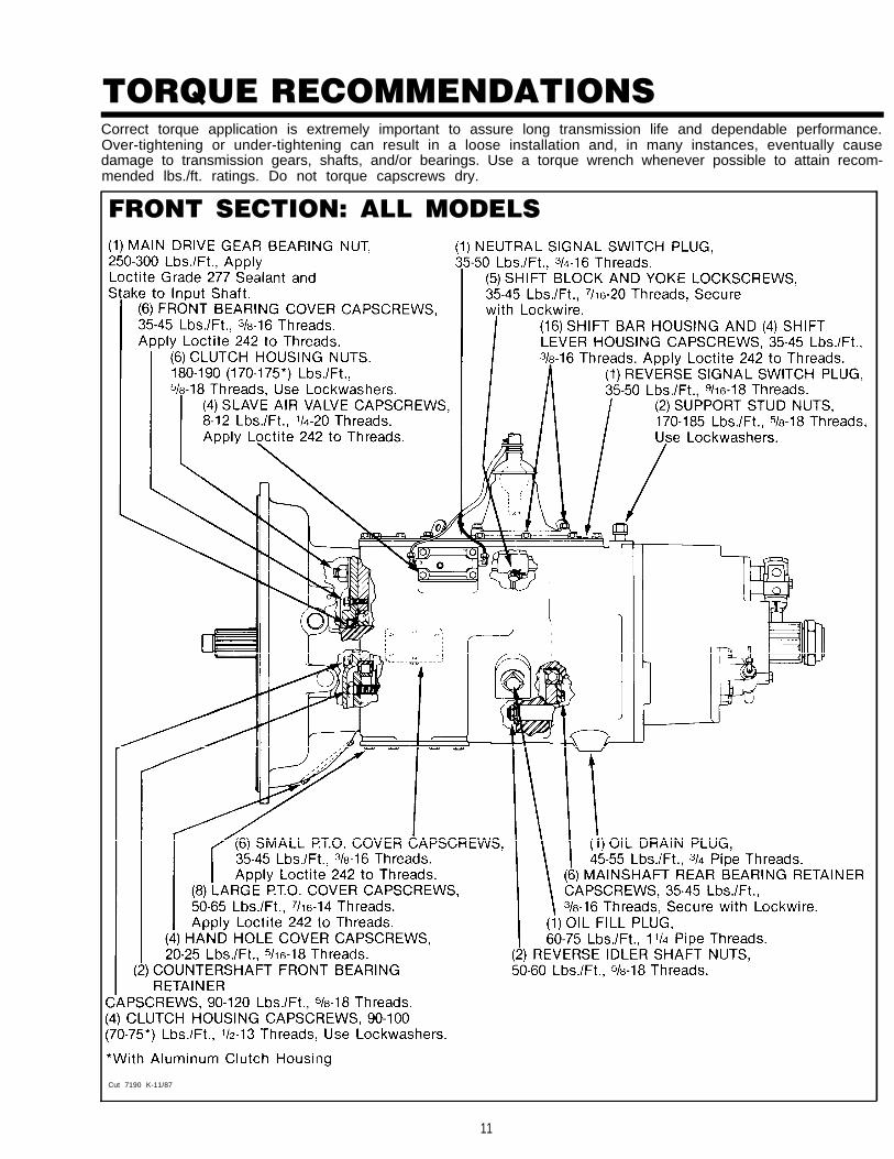
TORQUE RECOMMENDATIONSCorrect torque application is extremely important to assure long transmission life and dependable performance.Over-tightening or under-tightening can result in a loose installation and, in many instances, eventually causedamage to transmission gears, shafts, and/or bearings. Use a torque wrench whenever possible to attain recom-mended lbs./ft. ratings. Do not torque capscrews dry.
FRONT SECTION: ALL MODELS
1
Cut 7190 K-11/87
11

TORQUE RECOMMENDATIONS
AUXILIARY SECTIONS
Cut 7191 Q-11/87
12

TOOL REFERENCESome repair procedures pictured in this manual show The specialized tools listed below can be obtained from
the use of specialized tools. Their actual use is recom- a tool supplier or made from dimensions as required by themended as they make transmission repair easier, faster, individual user. Detailed Fuller Transmission Tool Prints areand prevent costly damage to critical parts. available upon request by writing.
But for the most part, ordinary mechanic’s tools such as Eaton Corporationsocket wrenches, screwdrivers, etc., and other standard Transmission Dept.shop items such as a press, mauls and soft bars are all that Technical Service Dept.is needed to successfully disassemble and reassemble any P.O. Box 4013Fuller Transmission. Kalamazoo, Michigan 49003
PAGE T O O L HOW OBTAINED
3 8 Tension Spring Driver Made from Fuller TransmissionPrint T-11938
4 6 Countershaft Retaining StrapMade from Fuller Transmission
Print T-64553
4 7 Auxiliary Section Hanger BracketMade from Fuller Transmission
Print T-22823
4 7 Output Shaft Hanger BracketMade from Stop Nut or Round
Bar Stock Flat Steel Stock
5 2 Jaw Puller and Bearing Separator Tool Supplier
6 9 Snap Ring Pliers Tool Supplier
7 2 Impact Puller (1/2-13 Threaded End) Tool Supplier
97 Countershaft Support ToolMade from Fuller Transmission
Print T-22247
9 9 Input Shaft Bearing Driver Tool Supplier
1 1 3 Torque Wrench, 1000 Lbs./Ft. Capacity Tool Supplier
13
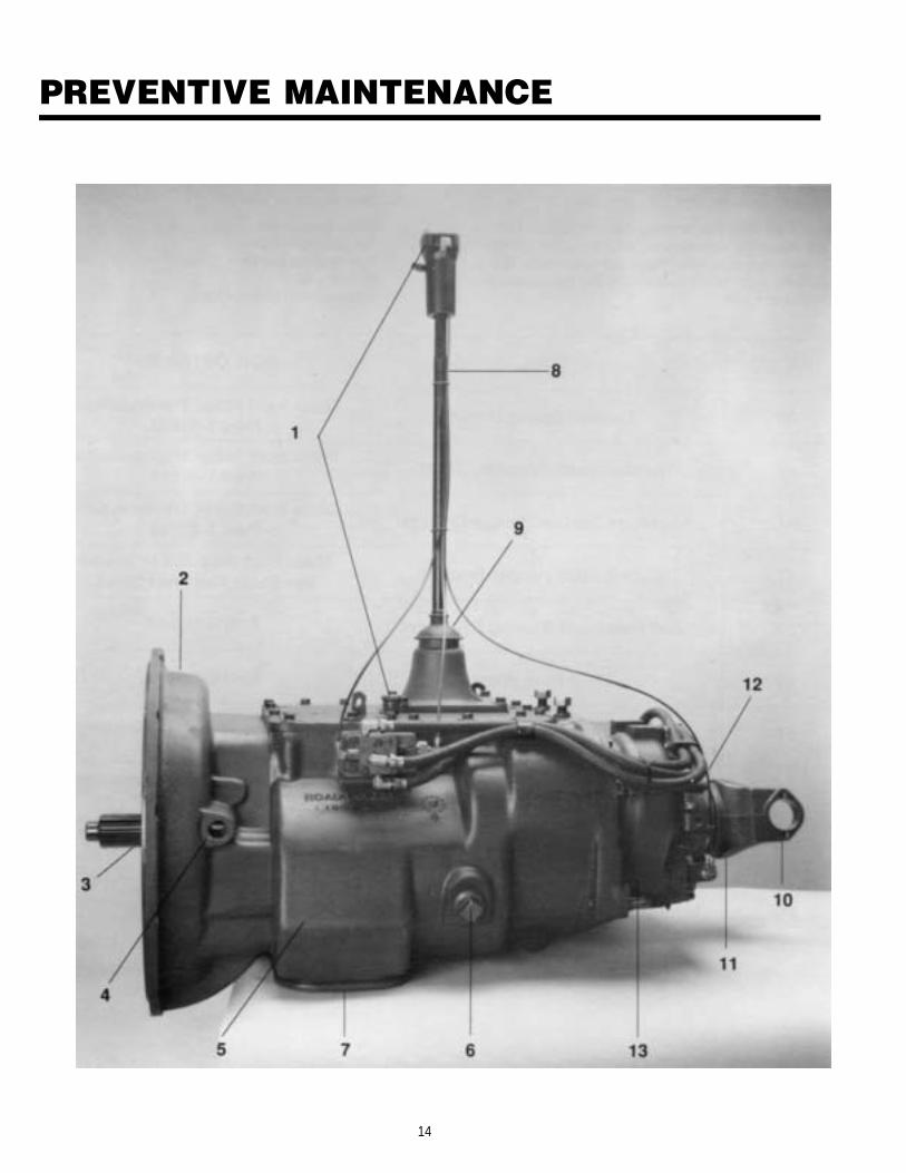
PREVENTIVE MAINTENANCE
14

PREVENTIVE MAINTENANCE
PREVENTIVE MAINTENANCE CHECK CHARTCHECKS WITHOUT PARTIALDISASSEMBLY OF CHASSIS OR CAB
1.
2.
3.
4.
5.
6.
7.
8.
Air System and Connectionsa. Check for leaks, worn air lines, loose con-
nections and capscrews. See AIR SYSTEM.
Clutch Housing Mountinga. Check all capscrews of clutch housing for
looseness.
Clutch Release Bearing (Not Shown)a. Remove hand hole cover and check radial
and axial clearance in release bearing.b. Check relative position of thrust surface of
release bearing with thrust sleeve on push-type clutches.
Clutch Pedal Shaft and Boresa. Pry upward on shafts to check wear.b. If excessive movement is found, remove
clutch release mechanism and check bush-ings in bores and wear on shafts.
Lubricanta. Change at specified service intervals.b. Use only the types and grades as recom-
mended. See LUBRICATION.
Filler and Drain Plugsa. Remove filler plugs and check level of lubri-
cant at specified intervals. Tighten filler anddrain plugs securely.
Capscrews and Gasketsa. Check all capscrews, especially those on
PTO covers and rear bearing covers forlooseness which would cause oil leakage.See TORQUE RECOMMENDATIONS.
b. Check PTO opening and rear bearing coversfor oil leakage due to faulty gasket.
Gear Shift Levera. Check for looseness and free play in hous-
ing. If lever is loose in housing, proceedwith Check No. 9.
9. Gear Shift Lever Housing Assemblya. Remove air lines at slave valve and remove
the gear shift lever housing assembly fromtransmission.
b. Check tension spring and washer for setand wear.
c. Check the gear shift lever spade pin andslot for wear.
d. Check bottom end of gear shift lever forwear and check slot of yokes and blocks inshift bar housing for wear at contact pointswith shift lever.
CHECKS WITH DRIVE LINE DROPPED
10. Universal Joint Companion Flangeor Yoke Nuta. Check for tightness. Tighten to recom-
mended torque.
11. Output Shaft (Not Shown)a. Pry upward against output shaft to check
radial clearance in mainshaft rear bearing.
CHECKS WITH UNIVERSAL JOINTCOMPANION FLANGE OR YOKEREMOVED
NOTE: If necessary, use solvent and shop rag toclean sealing surface of companion flange oryoke. DO NOT USE CROCUS CLOTH, EMERYPAPER OR OTHER ABRASIVE MATERIALSTHAT WILL MAR SURFACE FINISH.
12. Splines on Output Shaft(Not Shown)a. Check for wear from movement and chuck-
ing action of the universal joint companionflange or yoke.
13. Mainshaft Rear Bearing Covera. Check oil seal for wear.
15

PRECAUTIONSDisassembly
It is assumed in the detailed disassembly instructions that the lubricant has been drained from transmission,the necessary linkage and air lines disconnected and the transmission has been removed from vehicle chassis.Removal of the gear shift lever housing assembly (or remote control assembly) is included in the detailed in-structions (Disassembly and Reassembly—Shifting Controls); however, this assembly MUST be detached fromshift bar housing before transmission can be removed.
FOLLOW CLOSELY EACH PROCEDURE IN THE DETAILED INSTRUCTIONS. MAKING USE OF THE TEXT. ILLUS-TRATIONS AND PHOTOGRAPHS PROVIDED.
1 BEARINGS — Carefully wash and relubricate allreusable bearings as removed and protectivelywrap until ready for use. Remove bearings plannedto be reused with pullers designed for this pur-pose.
2. ASSEMBLIES — When disassembling the variousassemblies, such as the mainshaft, countershaft,and shift bar housing, lay all parts on a cleanbench in the same sequence as removed. This pro-cedure will simplify reassembly and reduce thepossibility of losing parts.
3. SNAP RINGS — Remove snap rings with Pliers de-
4
signed for this purpose. Snap rings removed in thismanner can be reused, if they are not sprung orloose.
INPUT SHAFT — The input shaft can be removed
5.
tershafts, mainshaft, or main drive gear. Specialprocedures are required and provided in this man-ual.
CLEANLINESS — Provide a clean place to work. Itis important that no dirt or foreign material entersthe unit during repairs, Dirt is an abrasive and candamage bearings. It is always good practice toclean the outside of the unit before starting theplanned disassembly.
6. WHEN USING TOOLS TO MOVE PARTS — Alwaysapply force to shafts, housings, etc, with restraint.Movement of some parts is restricted. Never applyforce to the part being driven after it stops solidly.The use of soft hammers, bars and mauls for alldisassembly work is recommended.
from transmission without removing the coun-
InspectionBefore reassembling the transmission, check each part carefully for abnormal or excessive wear and damage todetermine reuse or replacement. When replacement is necessary, use only genuine Fuller Transmission parts toassure continued performance and extended life from your unit.
Since the cost of a new part is generally a small fraction of the total cost of downtime and labor, avoid reus-ing a questionable part which could lead to additional repairs and expense soon after initial reassembly. To aidin determining the reuse or replacement of any transmission part, consideration should also be given to theunit’s history, mileage, application, etc.
Recommended inspection procedures are provided in the following checklist.
A. BEARINGS B. GEARS1.
2 .
3 .4 .
Wash all bearings in clean solvent. Checkballs, rollers and raceways for pitting, discol-oration, and spalled areas. Replace bearingsthat are pitted, discolored, or spalled.
Lubricate bearings that are not pitted, discol-ored, or spalled and check for axial and radialclearances.Replace bearings with excessive clearances.
Check bearing f i ts. Bearing inner racesshould be tight to shaft; outer races slightlytight to slightly loose in case bore. If bearingspins freely in bore, however, case should bereplaced.
1. Check gear teeth for frosting and pitting.Frosting of gear tooth faces present no threatof transmission failure. Often in continuedoperation of the unit, frosted gears will “heal”and not progress to the pitting stage. And inmost cases, gears with light to moderate pit-ted teeth have considerable gear life remain-ing and can be reused. But gears withadvanced stage pitting should be replaced.
2. Check for gears with clutching teeth abnor-mally worn, tapered, or reduced in lengthfrom clashing in shifting. Replace gearsfound in any of these conditions.
16

PRECAUTIONSInspection (cont’d.)
3. Check axial clearance of gears. Where exces-sive clearance is found, check gear snap ring,washer, spacer, and gear hub for excessivewear. Maintain .005” to .012” axial clearancebetween mainshaft gears.
C. SPLINES1. Check splines on all shafts for abnormal wear.
If sliding clutch gears, companion flange, orclutch hub have worn into the sides of thesplines, replace the specific shaft affected.
D. TOLERANCE WASHERS1. Check surfaces of all tolerance washers.
Washers scored or reduced in thicknessshould be replaced.
E. REVERSE IDLER GEAR ASSEMBLIES1. Check for excessive wear from action of roller
bearings.
F. GRAY IRON PARTS1. Check all gray iron parts for cracks and breaks.
Replace parts found to be damaged.
G. CLUTCH RELEASE PARTS1. Check clutch release parts. Replace yokes
worn at cam surfaces and bearing carrierworn at contact pads.
2. Check pedal shafts. Replace those worn atbushing surfaces.
H. SHIFT BAR HOUSING ASSEMBLY1.
2.
3.
4.
Check for wear on shift yokes and blocks atpads and lever slot. Replace excessively wornparts.
Check yokes for correct alignment. Replacesprung yokes.Check Iockscrews in yokes and blocks.Tighten and rewire those found loose.
If housing has been disassembled, checkneutral notches of shift bars for wear from in-terlock balls.
1. GEAR SHIFT LEVER HOUSINGASSEMBLY1. Check spring tension on shift lever. Replace
tension spring and washer if lever moves toof reel y.
2. If housing is disassembled, check spade pinand corresponding slot in lever for wear. Re-place both parts if excessively worn.
J. BEARING COVERS1. Check covers for wear from thrust of adjacent
bearing. Replace covers damaged from thrustof bearing outer race.
2. Check bores of covers for wear. Replacethose worn oversize.
K. OIL RETURN THREADSAND SEALS1. Check oil return threads in front bearing
cover. If sealing action of threads has beendestroyed by contact with input shaft, replacebearing cover.
2. Check oil seal in rear bearing cover If sealingaction of lip has been destroyed, replace seal.
L. SLIDING CLUTCHES1. Check all shift yokes and yoke slots in sliding
clutches for extreme wear or discolorationfrom heat.
2. Check engaging teeth of sliding clutches forpartial engagement pattern.
M. SYNCHRONIZER ASSEMBLY1. Check synchronizer for burrs, uneven and ex-
cessive wear at contact surface, and metalparticles.
2. Check blocker pins for excessive wear orlooseness.
3. Check synchronizer contact surfaces on theauxiliary drive and low range gears for exces-sive wear.
N. O-RINGS1. Check all O-rings for cracks or distortion. Re-
place if worn.
17

PRECAUTIONS—
Reassembly
Make sure that interiors of case and housings are clean. It is important that dirt and other foreign materials bekept out of the transmission during reassembly. Dirt is an abrasive and can damage polished surfaces ofbearings and washers. Use certain precautions, as listed below, during reassembly.
1.
2.
3.
4.
5.
GASKETS — Use new gaskets throughout thetransmission as it is being rebuilt. Make sure allgaskets are installed. An omission of any gasketcan result in oil leakage or misalignment ofbearing covers.
CAPSCREWS — To prevent oil leakage, use Loctite242 thread sealant on all capscrews. For torqueratings, see TORQUE RECOMMENDATIONS.
O-RINGS — Lubricate all O-rings with silicone lu-bricant.ASSEMBLY — Refer to the illustrations provided inthe detailed disassembly instructions as a guideto reassembly.
INITIAL LUBRICATION — Coat all limit washersand splines of shafts with Lubriplate during reas-sembly to prevent scoring and galling of suchparts.
6.
7.
8.
AXIAL CLEARANCES — Maintain original axialclearances of .005” to .012” for mainshaft gears.
BEARINGS — Use of flanged-end bearing drivers isrecommended for the installation of bearings.These special drivers apply equal force to bothbearing races, preventing damage to balls/rollersand races while maintaining correct bearing align-ment with bore and shaft. Avoid using a tubular orsleeve-type driver, whenever possible, as force isapplied to only one of the bearing races. SeeTOOL REFERENCE.
UNIVERSAL JOINT COMPANION FLANGE ORYOKE — Pull the companion flange or yoke tightlyinto place with the output shaft nut, using 450-500foot-pounds of torque. Make sure the speedome-ter drive gear or a replacement spacer of the samewidth has been installed. Failure to pull the com-panion flange or yoke tightly into place will permitthe output shaft to move axially with resultantdamage to the rear bearing.
IMPORTANT: REFER TO THE APPROPRIATE ILLUSTRATED PARTS LIST (SPECl-FIE D BY MODEL SERIES) TO ENSURE THAT PROPER PARTS AREUSED DURING REASSEMBLY OF THE TRANSMISSION.
18

CHANGING INPUT SHAFTSpecial ProcedureIn some cases, it may become necessary to replace the input shaft due to excessive clutch wear on the splines.Except for removal of the shift bar housing assembly, the input shaft can be removed without further disas-sembly of the transmission. Removal of the clutch housing is optional.
NOTE: The following illustration and instructions pertain to changing the input shaft ONLY. To change the maindrive gear, complete disassembly of the front section is required.
Disassembly Reassembly
1.
2.
3.
4.
5.
6.
7.
Remove the gear shift lever housing assembly (orremote control assembly) from shift bar housing,and the shift bar housing assembly from transmis-sion case.
Remove the front bearing cover and gasket. If nec-essary, remove the O-ring from cover of models soequipped.
Remove the bearing retaining snap ring fromgroove in shaft.
Push down on input shaft to cock bearing in bore.Drive input shaft toward rear of transmission,through bearing as far as possible. Pull input shaftforward to expose snap ring of bearing.
Use pry bars to complete removal of bearing.
Remove drive gear spacer and snap ring.
Pull input shaft forward and out of drive gear andcase.
1.
2.
3.
4.
5.
6.
7.
8.
9.
If necessary, install bushing in pocket of inputshaft.
Install new input shaft into splines of main drivegear, just far enough to expose snap ring groovein I.D. of drive gear.
Install snap ring in snap ring groove inside drivegear.
Install drive gear spacer on input shaft.
Install drive gear bearing on input shaft and intocase bore.
Install bearing retainer snap ring.
Install front bearing cover and gasket. Make sureto align oil return hole in the case with hole incover.
To facilitate proper reinstallation of the shift barhousing assembly on case, make sure mainshaftsliding clutches are placed in the neutral posi-tion.
Reinstall the shift bar housing assembly, thefront bearing cover and all other parts and as-semblies previously removed, making sure to re-place the gaskets used.
19

AIR SYSTEM
21

AIR SYSTEMRANGE SHIFT AIR SYSTEMOperationThe Range Shift Air System consists of the air filter/regulator, slave valve, a Range Control Valve or Mas-ter Control Valve, range cylinder, f i t t ings andconnecting air lines. See Air System Schematics.
CONSTANT AIR from the air filter/regulator is sup-plied to the “S” or Supply Port of slave valve andpassed through to the INLET or “S” Port of controlvalve.
WHILE IN LO RANGE, the control valve is OPENand AIR is returned to slave valve at the “P” or EndPort. This signals the valve to supply AIR in line be-tween the LO Range or “L” Port of slave valve andthe LO Range Port of range cylinder housing. AIR re-ceived at this port moves the range piston to the rearand causes the auxiliary LO RANGE gear to becomeengaged.
WHILE IN HI RANGE, the control valve is CLOSEDand NO AIR is returned to the slave valve. Thissignals the slave valve to supply AIR in line betweenthe HI Range or “H” Port of valve and the HI RangePort of range cylinder cover. AIR received at this portmoves the range piston forward to engage the aux-iliary drive gear with sliding clutch and bypass theLO RANGE gear set.
Range shifts can be made ONLY when the gearshift lever is in, or passing through, neutral. Thus, therange desired can be PRESELECTED while the shiftlever is in a gear position. As the lever is movedthrough neutral, the actuating plunger in the shift barhousing releases the slave valve, allowing it to moveto the selected range position.
Trouble ShootingIf the transmission fails to make a range shift orshifts too slowly, the fault may be in the Range ShiftAir System or actuating components of the shift barhousing assembly.
To locate the trouble, the following checks shouldbe made with normal vehicle air pressure applied tothe system, but with the engine off.
NEVER WORK UNDER A VEHICLEWHILE ENGINE IS RUNNING as
personal injury may result from the sudden and unin-tended movement of vehicle under power. Alwaysplace transmission in the neutral position.
1. INCORRECT AIR LINE HOOK-UPS(See Air System Schematics)With the gear shift lever in neutral, move the con-trol that provides range selection UP and DOWN.A. If the air lines are crossed between control
valve and slave valve, there will be CON-STANT AIR flowing from the exhaust port ofcontrol valve WHILE IN HI RANGE.
2.
3.
4.
B. If the air lines are crossed between the slavevalve and range cylinder, the transmissiongearing will not correspond with the range se-lection. A LO RANGE selection will result in aHI RANGE engagement and vice versa.
AIR LEAKSWith the gear shift lever in neutral, coat all airlines and fittings with soapy water and check forleaks, moving the control that provides range se-lection UP and DOWN.
A.
B.
C.
D.
If there is a steady leak from the exhaust portof control valve, O-rings and/or related partsof the control valve are defective.
If there is a steady leak from breather of slavevalve: an O-ring in valve is defective, or thereis a leak past O-rings of range cylinder piston.
If transmission fails to shift into LO RANGEor is slow to make the range shift and thecase is pressurized, see Check No. 7 of thissection.
Tighten all loose connections and replace de-fective O-rings and parts.
AIR FILTER/REGULATOR(See illustration, Page 23.)With the gear shift lever in neutral, check thebreather of air fiiter/regulator assembly. Thereshould be NO AIR leaking from this port. Thecomplete assembly should be replaced if asteady leak is found.
Cut off the vehicle air supply to the air filter/regulator assembly, disconnect the air line at fit-ting in Supply OUTLET and install an air gage inopened port. Bring the vehicle air pressure to nor-mal. Regulated air pressure should be 57.5 to 62.5Psi.
DO NOT ADJUST SCREW AT BOTTOM OF REGU-LATOR TO OBTAIN CORRECT READINGS. Theair regulator has been PREADJUSTED within thecorrect operating limits. Any deviation from theselimits, especially with regulators that have beenin operation for some time, is likely to be causedby dirt or worn parts. If replacement or cleaningof the filter element does nothing to correct theair pressure readings, replace the complete as-sembly, as the air regulator is nonserviceable.
RANGE VALVE (See Page 24.)With the gear shift lever in neutral, select HIRANGE and disconnect the air line at the OUT-LET or “P” Port of control valve.
21

AIR SYSTEM
5.
A.
B.
HI
When LO RANGE is selected, a steady blastof air will flow from opened port. Select HIRANGE to shut off air flow. This indicates thecontrol valve is operating properly. Reconnectair line.
If control valve does not operate properly,check for restrictions and air leaks. Leaks in-dicate defective or worn O-rings.
RANGE OPERATIONWith the gear shift lever in neutral, select LORANGE and disconnect the 1/4” I.D. air line at theport of range cylinder cover. Make sure this lineleads from the HI Range or “H” Port of slavevalve.
A.
B.
C.
When HI RANGE is selected, a steady blast ofair should flow from disconnected line. SelectLO RANGE to shut off air flow.
Move the shift lever to a gear position and se-lect HI RANGE. There should be NO AIR flow-ing from disconnected line. Return the gearshift lever to the neutral position. Thereshould now be a steady flow of air from dis-connected line. Select LO RANGE to shut offair flow and reconnect air line.
If the air system does not operate accord-ingly, the slave valve or actuating componentsof the shift bar housing assembly are defec-tive.
IMPORTANT: RANGE PRESELECTIONThe plunger pin, located in case bore betweenthe slave valve and actuating plunger of shift barhousing, prevents the slave valve from operatingwhile the shift lever is in a gear position. Whenthe lever is moved to or through the neutral po-sition, the pin is released and the slave valve be-comes operational.
6. LO RANGE OPERATIONWith the gear shift lever in neutral, select HIRANGE and disconnect the 1/4” I.D. air line at thefitting on range cylinder housing. Make sure thisline leads from the LO Range or “L” Port of slavevalve.
A.
B.
C.
When LO RANGE is selected, a steady blastof air should flow from disconnected line. Se-lect HI RANGE to shut off air flow.
Move the shift lever to a gear position and se-lect LO RANGE. There should be NO AIR flo-wing from disconnected line. Return the gearshift lever to the neutral position. Thereshould now be a steady flow of air from dis-connected line. Select HI RANGE to shut offair flow and reconnect air line.
If the air system does not operate accord-ingly, the slave valve or actuating componentsof the shift bar housing assembly are defec-tive.
7. RANGE CYLINDER (Refer to the followingillustration.)If any of the seals in the range cylinder assemblyare defective, the range shift will be affected.
A.
B.
C.
Leak at either O-ring A results in completefailure to make a range shift; steady flow ofair from breather of slave valve in bothranges.
Leak at gasket B results in a steady flow of airto atmosphere while in HI RANGE.
Leak at O-ring C results in a slow shift to LORANGE; pressurizing of transmission case.
Cut 7420-5/87
Range Cylinder Assembly—All Models
22

AIR SYSTEMAIR FILTER/REGULATOR ASSEMBLY
—.The air filter contains a replaceable filter element which can be removed by turning out the end cap. This ele-ment should be cleaned at each oil change, or more often under high humidity conditions. Replace if necessary.
SLAVE VALVESPOPPET-TYPE
Refer to the drawing for disassembly and reassembly of the piston-type slave valve assemblies. Should the pop-pet-type slave valve assembly prove to be defective, replace the complete assembly, as it is non-serviceable.The actuating components used with these valve assemblies are non-interchangeable. Failure to use the correctplunger pin, spring, and alignment sleeve during installation on the transmission will cause hard shifting in LORange gears.
23

AIR SYSTEM
ROADRANGER VALVE A-4900
Removal and Disassembly 7. If necessary, remove the spring and O-ring from1.
2.
3.
4.
5.
6.
Remove two screws holding bottom cover to valve bores in left housing.and slide cover down gearshift lever to expose air 8. If necessary, remove the springs, O-ring andline fittings. Disconnect air lines. sleeve from bores in right housing.Loosen jam nut and turn control valve from gearshift lever. Reassembly and InstallationPry medallion from recess in top cover.
1.Turn out the two screws to remove the top coverfrom valve housing.
Turn out the two screws in side of valve housing toseparate the housing.
Remove the Range Preelection Lever from left2.
housing and the position balls and guide fromlever. 3.
24
—
Refer to the drawing for proper reassembly. Use aVERY SMALL amount of silicone lubricant on theO-rings to avoid clogging ports. A small amount ofgrease on the position springs and balls will helpto hold them in place during reassembly
Install control valve on gear shift lever and tightenjam nut.
Attach air lines and install bottom cover.

AIR SYSTEMSPLITTER SHIFT AIR SYSTEM:Operation
In addition to the various components of the Range Shift AirSystem, the Splitter Shift Air System utilizes a splitter cylin-der and the Roadranger Valve A-4900. See Air SystemSchematics.
CONSTANT AIR from the air filter/regulator assembly issupplied to the splitter cylinder at the port on right side ofcylinder cover. The Insert valve installed in cover (seepage 27) provides the proper air flow needed to move thesplitter piston in the cylinder (rearward to engage rear auxil-iary drive gear for operation in direct; forward to engage thefront auxiliary drive gear for operation in overdrive).
WHILE IN HI OR LO RANGE, AIR needed to make thesplitter selection and complete the shift is supplied to theRoadranger valve from the tee fitting at the HI RANGE or“H” port of the slave valve. When the overdrive selection ismade, the AIR passes through the Roadranger valve and issupplied to the Left Port of cylinder cover.
With Splitter Control Button in the “DIRECT’’/REAR-WARD position, the “SP” Port of the Roadranger valve isCLOSED and NO AIR is supplied to the Left Port of theSplitter cylinder cover.
Button REARWARD(“SP” Port Closed)
While in HI RANGE the button can be moved FOR-WARD to operate in OVERDRIVE. The "SP” Port of valve isOPENED when overdrive is selected, supplying AIR to theLeft Port of the Splitter cylinder cover.
Button FORWARD(“SP” Port Opened)
Trouble Shooting
If the transmission fails to shift or shifts too slowly to or fromthe ‘(split” position, the fault may be in the Splitter Shift AirSystem or related components of the Range Shift Air Sys-tem.
To locate the trouble, the following checks should bemade with normal vehicle air pressure supplied to the sys-tem, but with the engine off.
NEVER WORK UNDER A VEHICLEWHILE ENGINE IS RUNNING as
personal injury may result from the sudden and unin-tended movement of vehicle under power. Alwaysplace transmission in the neutral position.
NOTE: It is assumed that correct PSI readings were
1.
2.
3.
obtained from the air filter/regulator and all airlines have been checked for leaks.
Air Supply (See Air System Schematics.)With the gear shift lever in neutral, select HI or LORANGE and loosen the connection at the "S“ Port ofthe Roadranger Valve until it can be determined thatAIR is supplied to valve. Reconnect air line.
If there is NO AIR, check for a restriction in the air linebetween the Roadranger valve and slave valve. Makesure this line is connected to fitting at the supply Port ofslave valve.
Roadranger Valve (See Page 24 and Air SystemSchematics.)With the gear shift lever in neutral, disconnect the airline at the Left Port of splitter cylinder cover, makingsure this line leads from the "SP” Port of theRoadranger Valve.A. WHILE IN HI OR LO RANGE, move the Splitter
Control Button FORWARD. There should be AIRflowing from disconnected line. Move the buttonREARWARD to shut off air flow and reconnect airline.
B. If the preceding conditions do not exist, theRoadranger valve is defective, or there is a restric-tion in the air lines.
Splitter Cylinder. (Refer to the following illustra-tion.)If any of the seals in the splitter cylinder assembly aredefective, the splitter shift will be affected. The degreeof air lost will govern the degree of failure, from slowshifting to complete shift failure.A. Leak at O-ring A results in a slow shift to engage
rear auxiliary drive gear; pressurizing of transmis-sion case; auxiliary gearing can be disengaged.
25
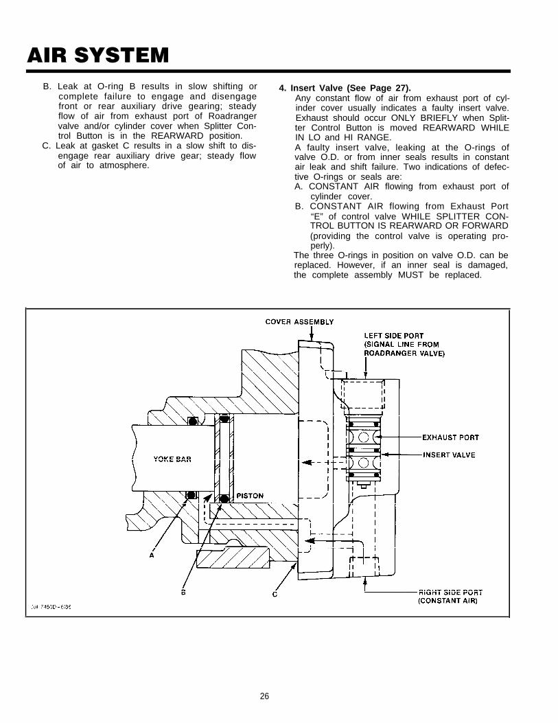
AIR SYSTEMB. Leak at O-ring B results in slow shifting or
complete failure to engage and disengagefront or rear auxiliary drive gearing; steadyflow of air from exhaust port of Roadrangervalve and/or cylinder cover when Splitter Con-trol Button is in the REARWARD position.
C. Leak at gasket C results in a slow shift to dis-engage rear auxiliary drive gear; steady flowof air to atmosphere.
4. Insert Valve (See Page 27).Any constant flow of air from exhaust port of cyl-inder cover usually indicates a faulty insert valve.Exhaust should occur ONLY BRIEFLY when Split-ter Control Button is moved REARWARD WHILEIN LO and HI RANGE.A faulty insert valve, leaking at the O-rings ofvalve O.D. or from inner seals results in constantair leak and shift failure. Two indications of defec-tive O-rings or seals are:A. CONSTANT AIR flowing from exhaust port of
cylinder cover.B. CONSTANT AIR flowing from Exhaust Port
“E” of control valve WHILE SPLITTER CON-TROL BUTTON IS REARWARD OR FORWARD(providing the control valve is operating pro-perly).
The three O-rings in position on valve O.D. can bereplaced. However, if an inner seal is damaged,the complete assembly MUST be replaced.
26

AIR SYSTEMINSERT VALVE:(EQUIPPED WITH ROADRANGER VALVE A-4900The insert valve is a self-contained 1 - 3/16” valve as- NOT be disassembled except for the three O-rings onsembly located in the splitter cylinder cover. It CAN- outer diameter. The O-rings provide a stationary seal
LOW RANGE AND HIGH RANGE DIRECT
and do not move in cylinder.When installing the insert valve in bottom edge of
cover, apply Fuller #71206 silicone lubricant or itsequivalent to O-rings and cylinder walls. Install valvein bore with flat surface to the outside. When install-ing the special valve retaining nut, apply Fuller#71204 adhesive/sealant or its equivalent to threadsand tighten. See TORQUE RECOMMENDATIONS.
Travel of the small insert valve piston is only 3/16”.As shown in the illustrations below, when NO AIR isapplied to the top side of valve piston, CONSTANTAIR supplied from the regulator passes to theFRONTSIDE of cylinder piston, moving the yoke barbackward to engage the REAR AUXILIARY DRIVEGEAR (LO RANGE DIRECT AND HI RANGE DIRECT).The piston moves up to cut off air to the back side ofthe cylinder piston. This air is exhausted out the cyl-inder cover as the piston moves rearward.
When AIR is applied to top side of valve piston,through signal line, the piston moves down passingair through the bottom of insert valve to the front andbackside of the cylinder piston, moving the yoke barFORWARD engaging the FRONT AUXILIARY DRIVEGEAR (LO RANGE OVERDRIVE AND HI RANGEOVERDRIVE).
OVERDRIVE
AIR APPLIED THROUGH SIGNAL LINEPUSHES INSERT VALVE PISTON DOWN
27

System Operation and Schematics—Operation Guide — 3A-21
For all questionsconcerningremoval andreplacement,refer to EatonService and PartsLiterature.
Schematic
A-5000 Valve
19470 Valve
Slave ValveIdentification
Air Filter/RegulatorAssembly
Range Cylinder Assembly
LO
HI
Constant Air
Air fromVehicleSource
Splitter CylinderAssembly SP
LO Range
RTLO-XX613 Models
No Air
Air toHousingPort
No Air
Down
A-4900 RoadrangerValve
P S SP
Rearward
TransmissionsFulerl ®
H/L
19470 or A-5000Slave Valve
HI
P
LO
S
H/L

3A-22 — Operation Guide—System Operation and Schematics
For all questionsconcerningremoval andreplacement,refer to EatonService and PartsLiterature.
Schematic
Air Filter/RegulatorAssembly
Range Cylinder Assembly
LO
HI
Constant Air
Air fromVehicleSource
Splitter CylinderAssembly SP
No Air
Air to CoverPort
HI Range L
RTLO-XX613 Models
A-5000 Valve
19470 Valve
Slave ValveIdentification
No Air
A-4900 RoadrangerValve
P S SP
TransmissionsFulerl ®
Rearward
Up
H/L
19470 or A-5000Slave Valve
HI
P
LO
S
H/L

System Operation and Schematics—Operation Guide — 3A-23
For all questionsconcerningremoval andreplacement,refer to EatonService and PartsLiterature.
Schematic
A-5000 Valve
19470 Valve
Slave ValveIdentification
Air Filter/RegulatorAssembly
Range Cylinder Assembly
LO
HI
Constant Air
Air fromVehicleSource
Splitter CylinderAssembly SP
No Air
Air to CoverPort
HI Range H
RTLO-XX613 Models
A-4900 RoadrangerValve
P S SP
TransmissionsFulerl ®
Forward
Up
H/L
19470 or A-5000Slave Valve
HI
P
LO
S
H/L

DISASSEMBLY SHIFTING CONTROLSAir System
A. Removal of Air Control
1. Disconnect the two air lines at the "S" or Supply Portand "P" or End Port of the slave valve on the transmis-sion case.
2. Remove the air line at the splitter cylinder cover.
NOTE: If desired, the gear shift lever housing assem-bly can now be removed from shift bar housing byremoving the four capscrews from the tower.
32

DISASSEMBLY SHIFTING CONTROLS
3. Turn out the two mounting screws in the Roadrangervalve cover.
4. Slide the cover down to expose the valve ports anddisconnect the three air lines.
33
5. Loosen the jam nut and turn the valve and nut fromgear shift lever. Remove the valve cover, air linessheathing and O-rings from lever.
6. Disconnect and remove the 1/4" I.D. air line betweenSplitter Cylinder and air filter/regulator.

DISASSEMBLY SHIFTING CONTROLS
7.
B.
Disconnect and remove the 1/4" I.D. air hoses be-tween the slave valve (inset) and air filter/regulatorassembly and range cylinder assembly.
Removal of Air
2. Turn out the four retaining capscrews and remove slavevalve from transmission case.
Filter/Regulator Assembly
3. Remove the hat-type alignment sleeve from bore inslave valve.
1. Turn out the two capscrews and remove the air filter/regulator assembly.
NOTE: For disassembly and reassembly of Air Filter/Regulator Assembly, see Page 23.
34

DISASSEMBLY SHIFTING CONTROLS
4. Remove the spring and plunger pin from bore in trans-mission case. Remove slave valve gasket.
5. If necessary, remove the air line fittings from slavevalve.
NOTE: For disassembly and reassembly of piston-typeSlave Valve Assembly, see Page 23.
35

DISASSEMBLY GEAR SHIFT LEVERASSEMBLY
Cut 7288D2/86
A. Removal and Disassembly
1. Turn out the four retaining capscrews, jar lightly tobreak gasket seal and remove the gear shift leverhousing and gasket from shift bar housing.
NOTE: Remote control housings are removed fromshift bar housing in the same manner. For disas-sembly and reassembly of LRC Assemblies, see 11-Iustrated Parts List No. P-541. For disassemblyand reassembly of SRC Assemblies, see illus-trated Parts List No. P-515.
2. Remove the boot from gear shift lever and secureassembly in vise with bottom of housing up. Use a largescrewdriver to twist between the spring and housing,forcing the spring from under the lugs in housing.Do one coil at a time.
36

REASSEMBLY GEAR SHIFT LEVERASSEMBLY
spade pin in leaver ball slot and install the tensionspr ing washer over ba l l , d ished-s ide up .
3. Remove the tension spring, washer and gear shiftlever from housing.
1. With the gear shift lever housing secured in viseas suring disassembly, install the spade pin inbore of housing tower. If previously removed, in-stall the O-ring in tower groove.
4. Remove the spade pin from bore in housingtower. If necessary, remove the O-ring from
2. Position the gear shift lever in housing with
groove inside tower.
B. Reassembly of Gear Shift LeverHousing Assembly
37

REASSEMBLY GEAR SHIFT LEVERASSEMBLY
3. Install the tension spring under lugs in housing, seatingone coil at a time. Use of a spring driving tool isrecommended.
4. Remove the assembly from vise and install therubber boot over gear shift lever and againsthousing.
38

DISASSEMBLY AND REASSEMBLYSHIFT BAR HOUSINGSHIFT BAR HOUSING ASSEMBLY
A. Removal and Disassembly of the ShiftBar Housing Assembly
For models equipped with an Oil Pumpand/or Cooler Assembl ies, make sure todisconnect the lube line at the fitting on the shiftba r hous ing be fo re do ing the fo l l ow inginstructions.
1. Turn out the retaining capscrews. Jar the top to 2. Tilt the assembly and remove the three sets of ten-break the gasket seal and lift the shift bar housingfrom the transmission case. Remove the gasket.
sion springs and balls from the housing bores.
NOTE: During disassembly, lay all parts on aclean bench in order of removal from the housingto make reassembly easier. Shift bars not being re-moved must be kept in the neutral position or theinterlocking parts will lock the bars.
39

DISASSEMBLY AND REASSEMBLYSHIFT BAR HOUSING
3. Secure the assembly in a vise with the plunger-side up. (The front of the housing will be to theleft.) For models so equipped, cut the lockwireand turn out the retaining capscrews to removethe oil trough from the housing.
NOTE: Start with the upper shift bar, move all barsto the right and out the rear boss bore. Cut thelockwire and remove the Iockscrews from each barjust before their removal.
4. Move the 3rd-4th speed shift bar to the housingrear, removing the yoke and block from the bar.
5. Move the 1st-2nd speed shift bar to the housingrear, removing the yoke and block from the bar. Asthe neutral notch in the bar clears the rear boss,remove the small interlock pin from the bore.
6. Remove the actuating plunger from the centerboss bore.
40

DISASSEMBLY AND REASSEMBLYSHIFT BAR HOUSING
B. Reassembly of the Shift Bar HousingA s s e m b l y .
7. Move the short LO-Reverse speed shift bar to thehousing rear, remove the yoke from the bar. As theshift bar is removed from the housing, two 3/4 in-terlock balls will drop from the rear boss bottombore.
1. If previously removed, install the reverse-stopplunger in the LO-Reverse shift yoke, making surethe plunger is fully seated in the yoke slot bore.
8. If necessary, remove the plug, spring, and reverse-stop plunger from the LO-Reverse speed shiftyoke bore.
2. Install the spring in the yoke bore and on theplunger shank.
41

DISASSEMBLY AND REASSEMBLYSHIFT BAR HOUSING
3. Install the plug and tighten to compress th espring (left). Back the plug out 1 - 1 1/2 turns andstake the plug through the small hole in the yoke(right.)
4. Secure the shift bar housing in a vise. Hold thenotched-end of the short LO-Reverse speed shiftbar, install the bar in the lower bore of the shift barhousing bosses. Install the yoke Iockscrew ,tighten and wire securely.
NOTE: Start with the lower shift bore of the rearboss and move to the left (front of the housing).Keep bars in the neutral position during installa-tion. DO NOT EXCEED the recommended torqueratings for the yoke Iockscrews as over-tighteningmay distort the shift bars.
5. While holding the plunger shank, install the ac-tuating plunger in the center boss bore.
6. Install one 3/4" interlock ball in the rear boss topbore. This ball rides between LO-Reverse and 1st-2nd speed shift bars.
42

DISASSEMBLY AND REASSEMBLYSHIFT BAR HOUSING
7. While holding the notched-end of the bar, installthe 1st-2nd speed shift bar in the housing bossmiddle bore. Position the shift block on the bar be-tween the center and rear bosses, and the yoke onthe bar between the front and center bosses, longhub to the housing front. Just before inserting thenotched-end of the rear boss bar, install the smallinterlock pin VERTICALLY in the neutral notchbore. Install the block and yoke Iockscrews,tighten, and lockwire securely.
NOTE: It is necessary that the interlock pin re-main in a vertical position during reassembly asrotation of the bar causes the pin to jam in the ten-sion spring bores.
9.
10.
While holding notched-end of the bar, install the3rd-4th speed shift bar in the housing boss upperbore, position the shift block on the bar betweenthe front and center bosses, long hub to thehousing rear. Install the block and yoke lock-screws, tighten, and lockwire securely.
For models so equipped, install the oil trough onthe housing. Tighten the capscrews and lockwiresecurely.
8. Install the other 3/4" interlock ball in the rear bosstop bore. This ball rides between the 1st-2nd andthe 3rd-4th speed shift bars.
43

DISASSEMBLY AND REASSEMBLYSHIFT BAR HOUSING
11. Remove the assembly from the vise. Install thethree tension balls, one in each bore on the hous-ing top.
12. Install the three tension springs, one over eachball in the housing bores.
44

REMOVAL - OUTPUT YOKE, AUXILIARYSECTION, AND CLUTCH HOUSING
A. Removal Output Yoke
1. Lock transmission by engaging two mainshaft gears 2. Pull yoke straight to the rear and off the output shaft.with the mainshaft sliding clutches (inset.) Use a largebreaker bar to turn the output shaft nut from the outputshaft.
45

REMOVAL - OUTPUT YOKE, AUXILIARYSECTION, AND CLUTCH HOUSINGB. Removal of the Auxiliary Section
Bar Stock - 3/8" x 1"Tool Print T-65853
1. Place the transmission in the vertical position. Putblocks under the clutch housing to prevent damage tothe input shaft. Removal can also be completed in thehorizontal position.
Do not use an air gun. Tighten byhand until the capscrews are snug.
4. Repeat Steps 2 and 3 for the remaining auxiliary coun-tershaft.
2. Remove the four capscrews and the auxiliary counter-shaft rear bearing cover, gasket, and rear bearing shim.
Auxiliary Countershaft Retaining Strapsmay be installed to hold countershaft in
place. Auxiliary can be removed without straps usecaution.
3. Install an Auxiliary Countershaft Retaining Strap with3-3/8" x 1" dean capscrews. Place a flat washer underthe strap to prevent damage to the rear auxiliary coun-tershaft bearing.
5. Remove the nineteen capscrews that hold the auxiliarysection to the transmission case.
NOTE: There are three lengths of capscrews, note theirlocation.
46

REMOVAL - OUTPUT YOKE, AUXILIARYSECTION, AND CLUTCH HOUSING
1. Insert three capscrews in the tapped holes of housingflange. Tighten evenly to move auxiliary section to therear and just far enough from front section to breakgasket seal.
2. Remove capscrews and attach a chain hoist to auxiliarysection. Move the assmbley to the rear until free of frontsection and remove gasket.
3. The auxiliary section can also be removed with thetransmission set in the vertical position. Block under theclutch housing to prevent damage to the imput shaft.Remove the retaining capscrews from the housing flange. Lift the assembly form the front section. Re-move the gasket
47

REMOVAL - OUTPUT YOKE, AUXILIARYSECTION, AND CLUTCH HOUSING
1. Remove the six capscrews, six nuts, and six lock-washers form studs that secure the clutch hous-ing to trasmission case.
2. . Jar the clutch housing with a rubber mallet tobreak gasket seal and pull from transmissioncase. Remove gasket.
48
D. Removal Clutch Housing
NOTE: For models so equipped remove theclutch release mechanism and/or clutch brakeassembly.

DISASSEMBLY - AUXILIARY SECTION
A. Removal and Disassembly RearAuxiliary Drive Gear and Yoke
1. Cut the lockwire on the splitter yoke retaining bolt and 2. Remove the retaining bolt, splitter yoke and slidingloosen the bolt. clutch assembly from the auxiliary section.
49

DISASSEMBLY - AUXILIARY SECTION
AUXILIARY MAINSHAFTASSEMBLY
WASHER
SPACER
b
GEAR
c
SLIDING REAR AUXILIARYCLUTCH DRIVE GEAR
Cut 6593 L-4/87
NUT
WASHER
3. Temporarily install an output yoke on the output shaftand secure it by placing a bar through the yoke.
4. Break loose the 15/16" retaining capscrew on the frontof the output shaft.
50

DISASSEMBLY - AUXILIARY SECTION
AUXILIARY COUNTERSHAFTASSEMBLY
Cut 6503M-11/91
B. Removal of the AuxiliaryCountershaft Assemblies
1. Secure the auxiliary housing in a vise. Remove theauxiliary countershaft retaining straps or rear bearingcovers, shim and rear bearing race.
auxiliary section.The countershaft will fall loose in the
2. Use a soft bar and maul to partially drive the outputshaft forward.
51

DISASSEMBLY - AUXILIARY SECTIONC. Removal Rear Auxiliary Drive Gear
Assembly
3. Remove the auxiliary countershaft from the auxiliarysection case.
1. Remove the 15/16" retaining capscrew, retainer andauxiliary drive gear from the auxiliary section.
4. If necessary, secure the countershaft assemblies in avise and remove both the front and rear bearings with abearing separator and jaw pullers.
52

DISASSEMBLYÑ AUXILIARY SECTION
RANGE CYLINDERASSEMBLY
*Note: Use lockwire atCut 6427-5/83 this position
D. Removal and Disassembly of RangeCylinder Assembly.
1. Remove the capscrews, range cylinder cover, andgasket.
2. Remove nut from yoke bar.
53

DISASSEMBLY-AUXILIARY SECTION
3. Cut the lockwire. Remove the two 3/4" yoke lock-screws (inset).
4. Pull the yoke bar from the cylinder housing bore.
5. Remove the shift yoke and synchronizer assemblyfrom output shaft.
6. Remove the range piston from the cylinder bore. Ifnecessary, remove the O-rings from the positionI.D. and O.D. (inset).
54

DISASSEMBLY-AUXILIARY SECTION
7. Remove capscrews and range cylinder housing.
8. If necessary, remove the small O-ring from therange cylinder housing bore.
55

DISASSEMBLY-AUXILIARY SECTION
E. Disassembly Synchronizer Assembly
1. Place the larger LO range synchronizer ring on thebench. Cover the assembly with a shop rag to pre-vent losing the three springs released from thehigh range synchronizer at the pin locations. Pullthe HI range synchronizer from the blocker pins.
2. Remove the sliding clutch from the synchronizerring LO range pins.
56

DISASSEMBLY-AUXILIARY SECTIONF. Removal and Disassembly Output Shaft
and Rear Bearing Assemblies.
1. Use a soft bar and maul to drive the output shaftforward and through the rear bearing assembly.
2. Remove the bearing inner spacer from the outputshaft.
3. Use the front face of the reduction gear as a base,press the output shaft through the bearing andgear. This frees the bearing, LO range gear, andthe splined washer.
4. Remove the stepped washer, LO range gear, andsplined washer from the shaft.
57

DISASSEMBLY - AUXILIARY SECTIONG. Removal Splitter Cover
5. Remove the rear bearing retaining capscrews, rearbearing cover, and gasket from the auxiliary housing.The rear bearing cone drops from the housing borewhen the cover is removed. If necessary, remove theoil seal from the cover (inset).
1. Remove the capscrews from the splitter cylinder coverand remove the splitter cylinder cover and gasket fromthe auxiliary section case.
6. Remove the two bearing cups and spacer from thebearing bore.
2. If necessary, turn out the insert valve retaining nut andremove insert valve from bore.
58
DISASSEMBLY - AUXILIARY SECTION
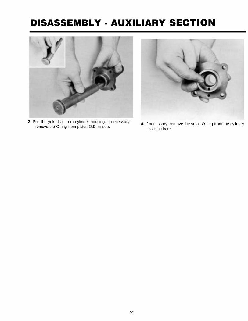
3. Pull the yoke bar from cylinder housing. If necessary,remove the O-ring from piston O.D. (inset).
4. If necessary, remove the small O-ring from the cylinderhousing bore.
59

REASSEMBLY-AUXILIARY SECTION
A. Reassembly and Installation of
NOTE: Make sure magnetic plugs preinstalled inauxiliary housing.
1. IMPORTANT: Mark timing teeth on the LO Rangegear. A highly visible color of toolmaker's dye is
a.
b.
recommended.Mark any two adjacent gear teeth on LO Rangegear, front side.Then mark the two adjacent teeth which aredirectly opposite the first set marked. Thereshould be the same number of teeth betweenthe markings on each side of the gear.
2. Placed splined washer on output shaft shoulderfacing up as shown.
60

REASSEMBLY-AUXILIARY SECTION
3. Install the LO Range gear on the output shaft,clutching teeth engaged with the splines down toengage the washer splines.
4. Install the LO Range gear rear washer on outputshaft and against gear, with chamfer side facingup.
5. Using a heat lamp or hot plate and oil heat the out-put shaft rear bearing and install on output shaft.Seat the bearing securely on shaft. Bearing canalso be installed using the appropriate driver.
NOTE: DO NOT HEAT BEARING ABOVE 275oF(136oC).
6. Install the bearing inner spacer on the outputshaft.
61

REASSEMBLY - AUXILIARY SECTION
7.
B.
Place the auxiliary housing on a flat bench and installthe 2 bearing cups and spacer in the rear bearing bore,the cup with a lip seats next to the rear of the auxiliarycase.
Reassembly Synchronizer Assembly
2. Install the three springs in bores in HI range synchro-nizer ring.
3. Place the HI range synchronizer ring over pins of LOspeed synchronizer ring, seating springs against pins.
1. Place the larger LO range synchronizer ring face downon bench with pins up. Place the sliding clutch, re-cessed side up, on pins of LO range synchronizer.
NOTE: Pins on LO range synchronizer must line upwith chamfered holes on bottom of sliding clutch.
62

REASSEMBLY - AUXILIARY SECTION
4. Apply downward pressure to the HI range synchronizerring WHILE TWISTING COUNTER-CLOCKWISE tocompress the springs and fully seat ring on blocker pinsof LO range synchronizer. It is suggested that a shoptowel be placed over the synchronizer to prevent injuryto your hands.
5. Install synchronizer assembly to front of output shaftassembly.
C. Installation of Auxiliary Driver Gear.
1. Place auxiliary drive gear, retainer and Òk capscrew onoutput shaft assembly. Secure capscrew on shaft tilltight, recommended torque will be applied during finalassembly (pg. 67)
D. Reassembly of AuxiliaryCountershaft Assemblies andTiming.
To make reassembly of the auxiliary section easier, you canmake this auxiliary section fixture out of a section of 2 x 12.
63

REASSEMBLY - AUXILIARY SECTION
NOTE: Auxiliary countershaft bearings will be installedat this time if replacement was required.
1. Mark each countershaft for correct timing. Locate the"O" stamped on the countershaft and mark the toothwith highly visible toolmakers dye or paint.
3. Install the range yoke into the synchronizer slidingclutch slot, offset side facing down.
2. Place the countershaft in fixture or on a flat surface forreassembly. Locate output shaft assembly betweencountershaft, timing of the auxiliary will be checked atthis time. The single marked tooth of each countershaftmust align with the two teeth marked on each side ofthe LO range gear,
4. Place the auxiliary housing over countershaft assem-blies and output shaft assemblies.
64

REASSEMBLY - AUXILIARY SECTION
5. Heat the rear output shaft bearing cone and install thebearing on the shaft taper side down.
NOTE: Do not heat the bearing above 275oF (136oC).
6. Install the rear bearing cover on the auxiliary housing.The nylon collar and brass washer are installed in thechamfered hole on the lower right side of the cover.
NOTE: Because the collar becomes distorted whencompressed, DO NOT REUSE OLD NYLON COLLAR.
E. Reassembly Range Cylinder
1. Install O-ring in slot of small bore in cylinder. Applysilicone to all O-rings (inset).
2. If previously removed, install the O-rings in the I.D. andO.D. of the range position.
65

REASSEMBLY - AUXILIARY SECTION
3.
4.
Position new gasket on housing. Install range cylinder,piston yoke, piston and retaining nut into housing.Tighten retaining nut to recommended torque. Install 4capscrews into range cylinder housing and tighten torecommended torque.
Place range cylinder cover and new gasket on rangecylinder, install 4 capscrews and tighten to recom-mended torque.
F. Reassembly and Installationof Splitter Cylinder Assembly
1. If previously removed, install the small O-ring in thecylinder housing bore.
2. If removed, install the O-ring on the piston O.D. (left).Insert the yoke bar in the cylinder housing bore (right).
66

REASSEMBLY - AUXILIARY SECTIONG. Reassembly of Auxiliary Rear
Bearing Assembly
1.
3. If previously removed, install the insert valve, flat end tothe outside, and the valve retaining nut in the bottombore of the cylinder cover. Tighten to recommendedtorque ratings.
NOTE: Prior to installation of the insert valve, makesure the three O-rings on the valve O.D. are not defec-tive. Replace, if necessary.
H.
Place the rear bearing cone over the bearing and intothe rear bore. Align the .100 shim over the cone andinstall the rear bearing cover with 4 capscrews tightenonly till snug (right). Retaining straps may also be usedat this time they are required for horizontal installation.Complete assembly by installing remaining rear bear-ing cover (left).
Installation of Range YokeCapscrews and RecommendedTorque of Auxiliary Drive Gear Nut
1. Install the 2 capscrews into the range yoke and tightento recommended torque (right). Tighten auxiliary drivegear retaining nut to recommended torque (left).
4. Place the new splitter cylinder gasket, splitter cylinderassembly, new splitter cylinder cover gasket and split-ter cylinder cover onto the auxiliary housing. Install 4capscrews into the assembly and tighten to recom-mended torque.
67
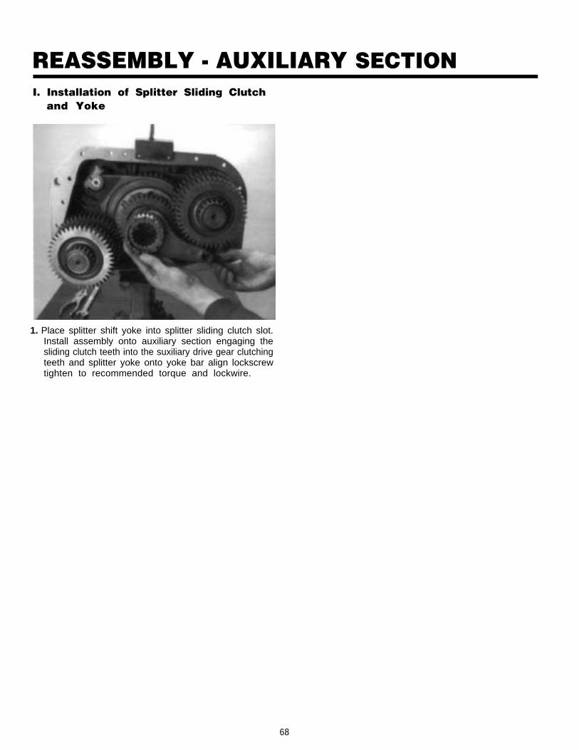
REASSEMBLY - AUXILIARY SECTIONI. Installation of Splitter Sliding Clutch
and Yoke
1. Place splitter shift yoke into splitter sliding clutch slot.Install assembly onto auxiliary section engaging thesliding clutch teeth into the suxiliary drive gear clutchingteeth and splitter yoke onto yoke bar align lockscrewtighten to recommended torque and lockwire.
68

DISASSEMBLY - FRONT SECTION
AUXILIARY DRIVE GEARASSEMBLY
*Note: Use lock wire atCut 6417 L -3 /87 this position
A. Removal Front Auxiliary Drive Gear
1. Cut lockwire from auxiliary bearing retainer ringcapscrews.
2. Remove snap ring from mainshaft rear groove.
69

DISASSEMBLY - FRONT SECTION
3. Remove the splined washer from inside front auxiliarydrive gear assembly.
5. Remove front auxiliary drive gear from mainshaft.
4. Remove six capscrews from the auxiliary bearing re-tainer ring. Insert three puller screws in the speciallytapped holes of retainer ring. Tighten screws evenly topull the front auxiliary drive gear assembly from casebore.
6. Remove the spline d washer from the mainshaft alsoremove the front auxiliary drive gear retaining snap ringfrom the mainshaft.
70?

DISASSEMBLY-FRONT SECTION
Cut 6382-9 /80
B. Removal and Disassembly of LeftReverse Idler Gear Assembly
1. Move the mainshaft reverse gear as far to the rearas possible and remove the snap ring from I.D. ofgear.
2. Move the reverse gear forward and against the LOspeed gear, engaging the splines of mainshaftsliding clutch.
71

DISASSEMBLY - FRONT SECTION
3. Using inside jaw pullers or impact puller, remove theauxiliary countershaft front bearing race from leftreverse idler gear bore. If necessary, repeat theprocedure for removing the auxiliary countershaft frontbearing race from right reverse idler gear bore.
5. Remove the pipe plug from rear of idler shaft and usean impact puller, 1/2"-13 threaded end, to remove shaftfrom case bore (inset).
4. Loosen the nut on the idler shaft, (inset). Remove thestop nut and washer from front of idler shaft.
6. As the idler shaft and idler plate are moved to the rear,remove the thrust washer, and gear from case. If nec-essary, remove the inner race from bearing andremove needle bearing from idler gear.
72

DISASSEMBLY-FRONT SECTIONc. Removal of Countershaft Bearings
NOTE: In the following instructions, the frontand rear bearings from BOTH countershaft areremoved. For removal of the mainshaft assemblyfrom case, it is necessary to remove the bearingsfrom right countershaft ONLY.
1. Temporarily reinstall front auxiliary drive gear onmainshaft, remove snap ring from each counter-shaft rear groove.
3. Remove front bearing cover.
2. Remove six capscrews from front bearing cover. 4. From inside the case, use a soft bar and maul todrive the countershaft rear bearings to the rearand from case bores.
NOTE: This procedure will damage the bearingsand should not be attempted unless replacementof the bearings is planned.
73

DISASSEMBLY-FRONT SECTION
5. Turn out the capscrew and remove the frontbearing retainer plate from each countershaft.
7. From the case rear, use a soft bar and maul todrive each countershaft forward to unseat thefront bearings from case bores and expose thebearing snap rings.
8. Use a bearing puller or pry bars to remove thecountershaft front bearings.
NOTE: The bearing inner race of models equippedwith roller-type front bearings will remain pressedon countershaft.
6. Use a soft bar and maul to drive each countershaftto the rear as far as possible. This will partially un-seat the front bearings.
NOTE: The soft bar used should have a flattenedend that is large enough so as not to damageholes for roll pin and capscrew.
74

DISASSEMBLY-FRONT SECTION
D. Removal and Disassembly of MainshaftAssembly
1. Block the right countershaft assembly againstcase wall and pull the mainshaft assembly to therear to free pilot from input shaft pocket. Tilt frontof mainshaft up and lift the assembly from case(inset). Use caution as the reverse gear is free andcan fall from shaft.
2. Remove the 3rd-4th speed sliding clutch frommainshaft front.
75
DISASSEMBLY-FRONT SECTION
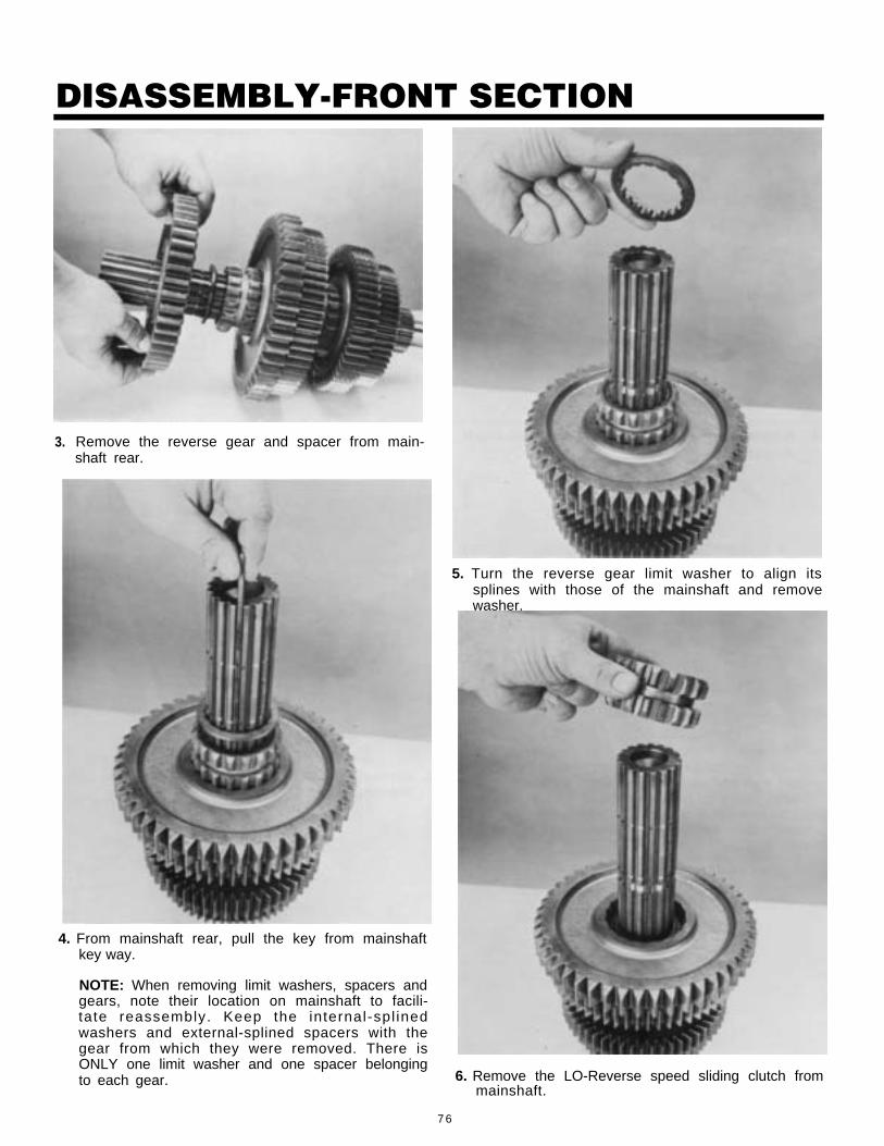
3. Remove the reverse gear and spacer from main-shaft rear.
5. Turn the reverse gear limit washer to align itssplines with those of the mainshaft and removewasher.
4. From mainshaft rear, pull the key from mainshaftkey way.
NOTE: When removing limit washers, spacers andgears, note their location on mainshaft to facili-tate reassembly. Keep the internal-spl inedwashers and external-splined spacers with thegear from which they were removed. There isONLY one limit washer and one spacer belongingto each gear. 6. Remove the LO-Reverse speed sliding clutch from
mainshaft.
7 6

DISASSEMBLY-FRONT SECTION
7. Using a small screwdriver, turn the limit washer inhub of LO speed gear to align its splines withthose of the mainshaft. Pull the LO speed gearfrom rear of mainshaft to remove limit washer,spacer, and gear. If necessary, remove the snapring from I.D. of gear (inset).
8. Remove each remaining gear, limit washer, spacer,and sliding clutch from mainshaft in the samemanner previously detailed. And, if necessary, re-move the snap ring from I.D. of each gear.
77

DISASSEMBLY-FRONT SECTION
DRIVE GEARASSEMBLY
E. Input Shaft Removal
2. Use a rubber maul on the input shaft to cock thebearing in bore.
1. Remove the bearing retaining snap ring fromgroove in shaft.
78

DISASSEMBLY-FRONT SECTION
3. Drive input shaft toward rear of transmission,through bearing as far as possible. Pull inputshaft.
5. Remove drive gear spacer, and snap ring (inset).
6. Pull input shaft forward and out of drive gear andcase.
4. Use pry bars or screwdriver to complete removalof bearing.
79

DISASSEMBLY-FRONT SECTION
8. Remove main drive gear from case.
7. Check the bushing in pocket of input shaft , re-place if worn.
80

DISASSEMBLY - FRONT SECTION
F. Removal and Disassembly ofCountershaft Assemblies
NOTE: Except for the PTO gears, the left and rightcountershaft assemblies are identical and disas-sembled in the same manner.
1. Move the right countershaft assembly to the rear as far. .
as possible so front of shaft can be removed from casebore and moved to the center of the case. Lift the
2. Remove the drive gear retaining snap ring from front ofeach countershaft.
assembly from case and repeat the procedure for leftcountershaft assembly.
NOTE: The left and right reverse idler gear assembliesare identical and disassembled in the same manner. Ifremoval and disassembly of this assembly is neces-sary, refer to Part B of this section.
81
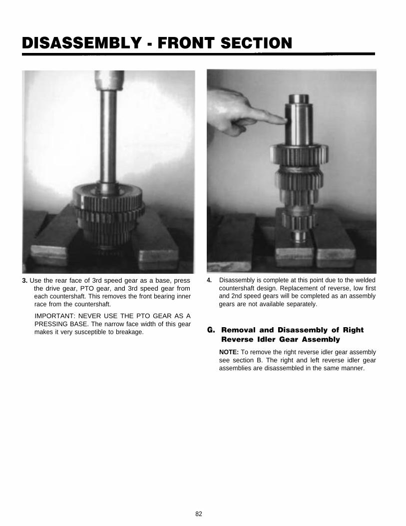
DISASSEMBLY - FRONT SECTION
3. Use the rear face of 3rd speed gear as a base, pressthe drive gear, PTO gear, and 3rd speed gear fromeach countershaft. This removes the front bearing innerrace from the countershaft.
IMPORTANT: NEVER USE THE PTO GEAR AS APRESSING BASE. The narrow face width of this gearmakes it very susceptible to breakage.
4.
G.
Disassembly is complete at this point due to the weldedcountershaft design. Replacement of reverse, low firstand 2nd speed gears will be completed as an assemblygears are not available separately.
Removal and Disassembly of RightReverse Idler Gear Assembly
NOTE: To remove the right reverse idler gear assemblysee section B. The right and left reverse idler gearassemblies are disassembled in the same manner.
82

DISASSEMBLY-FRONT SECTION
H. Removed and Disassembly of IntegralOil Pump
2. Remove three Allen head capscrews and washersthat retain the integral oil pump to front of case.
1. Straighten Iocktang on suction tube (inset), re-move suction tube from oil pump. If necessary re-move O-ring from suction tube.
83

DISASSEMBLY-FRONT SECTION
3. Remove the integral oil pump from case. 5. Remove outer oil pump element from pump.
4. Remove integral oil pump retainer plate from case. 6. Remove drive gear retaining snap ring from driveshaft.
84

DISASSEMBLY-FRONT SECTION
7. Remove drive gear from pump drive shaft
8. Remove key from drive shaft keyway.
9. Remove element retaining snap ring from driveshaft.
10. Remove internal oil pump element from driveshaft.
85

DISASSEMBLY-FRONT SECTION
.
11. Remove two keys from drive shaft keyways.
12. Remove the drive shaft from integral oil pumphousing. If necessary, remove rear drive gear re-tention snap ring from drive shaft.
13. Remove relief valve roll pin from pump housing,relief valve spring can now be removed from re-
14. Remove relief valve from housing bore.
15. If necessary front case plug can be removed fromcase by driving the plug through front of case.Remove O-ring from O.D. of plug if necessary.
Iief valve housing bore (inset).
86

DISASSEMBLY-FRONT SECTION1. Disassembly Auxiliary Drive Gear
Assembly
1. Remove the snap ring from hub of front auxiliarydrive gear.
3. If necessary, remove the O-rings from hub O.D. offront auxiliary drive gear.
2. Using the rear face of retainer ring as a base,press the drive through bearing.
87

REASSEMBLY-FRONT SECTION
1. If previously removed, install the O-rings onextended front hub of front auxiliary drive gear.
2. Install the retainer ring on front auxiliary drivegear, snap ring groove facing front hub and awayfrom gear teeth.
3. Start the front auxiliary drive gear bearing on fronthub, bearing snap ring facing groove in retainerring. Using both hands, press the bearing on gearwith snap ring in groove of retainer ring (inset).
4. Install the snap ring in groove of front gear hub toretain bearing.
,88
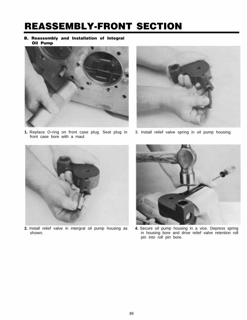
REASSEMBLY-FRONT SECTIONB. Reassembly and Installation of Integral
Oil Pump
1. Replace O-ring on front case plug. Seat plug infront case bore with a maul.
2. Install relief valve in intergral oil pump housing asshown.
3. Install relief valve spring in oil pump housing.
4. Secure oil pump housing in a vice. Depress springin housing bore and drive relief valve retention rollpin into roll pin bore.
89

REASSEMBLY-FRONT SECTION
5. If removed replace drive shaft snap ring on pumpdrive shaft and insert drive shaft through pumphousing bore as shown.
6. Install two keys on drive shaft (inset), and installintegral oil pump inner element on drive shaft,aligning keys on drive shaft with keyways on innerelement.
NOTE: Place round key in the round keyway;square key in the square keyway.
8.
7. Install inner element retention snap ring in driveshaft snap ring groove.
Install drive gear key in keyway of drive shaft (in-set), install drive gear on drive shaft aligning key-way on drive gear with key on drive shaft.
90

REASSEMBLY-FRONT SECTION
9. Install outer drive gear retention snap ring ingroove of drive shaft.
11. Install integral oil pump retainer over alignmentpin inside of case, bore in retainer facing rear ofcase.
10. Install outer integral oil pump element over innerelement.
12. Install integral oil pump assembly in case align-ing front face of oil pump with retainer and align-ment pin.
91

REASSEMBLY-FRONT SECTION. . .
13. Install three capscrews and washers throughfront of case and into pump housing, tightencapscrews to recommended torque.
14. Replace O-ring on suction tube and install tubeunder case rib and into integral oil pump. BendIocktang of suction tube over case rib.
92

REASSEMBLY - FRONT SECTIONCASE ASSEMBLIESNOTE: Before starting reassembly, make sure the threemagnetic discs are solidly in place at bottom of case. Thesecan be secured to disc mounting surfaces with Scotch GripRubber Adhesive or equivalent adhesive.
C. Reassembly and Installation of RightReverse Idler Gear Assembly
2. Install the bearing inner race on idler shaft and insertshaft into case bore, threaded-end of shaft to the front.As the idler shaft is moved forward, install the reverseidler gear on shaft, long hub to the front and seating onbearing inner race. Position the thrust washer on shaftbetween the gear and support boss in case and con-tinue with movement of idler shaft forward into bore ofSupport boss.
1. If previously removed, thread pipe plug in rear of re-verse idler shaft and tighten. Install the thrust washer tothe end of the idler shaft.
NOTE: If previously removed, replace the needle bear-ing into bore of reverse idler gear.
3. Making sure that the reverse idler shaft is seated inbore of support boss and forward as far as possible,install the washer and stop nut on front of shaft. Tightennut to recommended torque rating.
93

REASSEMBLY - FRONT SECTIOND. Reassembly of Countershaft
Assemblies
NOTE: Except for the PTO gears, the left and rightcountershaft assemblies are identical and reassembledin the same manner.
NOTE: Reverse low, 1st and 2nd speed gears are partof the shaft and are note serviceable.
4. Install the OUTER RACE of auxiliary countershaft frontbearing into case bore.
NOTE: The bearing INNER RACE is installed on frontof auxiliary countershaft and never with outer race.
1. Press the 3rd speed gear on the countershaft, long hubof gear to countershaft front.
94

REASSEMBLY - FRONT SECTION
2. Start the PTO gear onto countershaft, bullet-nose sideof teeth facing up and toward rear of shaft. Align key-way of drive gear with key in countershaft and pressBOTH gears onto shaft, long hub of drive gear againstPTO gear.
NOTE: The left countershaft assembly has a 47-toothPTO gear; the right countershaft assembly has a 45-tooth PTO gear.
3. To avoid confusion during installation, mark the end ofleft countershaft with an "L", the end of right counter-
4. Install the drive gear retaining snap ring in groove onfront of each countershaft.
5. Use a flanged-end driver to install bearing inner race oncountershaft, shoulder of race against shoulder of coun-tershaft.
shaft with an "R".
95
,

REASSEMBLY - FRONT SECTIONE. Partial Installation of Countershaft
Assemblies
IMPORTANT: Mark the countershaft drive gear for timingpurposes. On the drive gear of each countershaft assem-bly, mark the tooth aligned with keyway of gear andstamped with an "O" for easy identification. A highly visiblecolor of toolmakers' dye is recommended for making timingmarks.
1. Place the left countershaft assembly into position incase, making sure that the "L"-marked assembly hasthe larger 47-tooth PTO gear. Place the right counter-shaft assembly into position in case, making sure thatthe "R"-marked assembly has the smaller 45-tooth PTOgear.
96

REASSEMBLY-FRONT SECTIONF. Bearing Installation of Left Countershaft
Assembly
1. Move the left countershaft assembly to the rearand insert countershaft support tool or blockingto center shaft in rear case bore.
3. Center the front of left countershaft in bearing andmove the assembly forward.
2. Use a flanged-end bearing driver to start thebearing in case bore.
NOTE: The inner race of roller-type front bearingis pressed on front of countershaft.
4. Use a flanged-end bearing driver to completelyseat front bearing or bearing outer race in casebore.
97, . . .

REASSEMBLY-FRONT SECTIONG. Reassembly, Installation and Timing of
Main Drive Gear Assembly
5. Position the retainer plate on front of left countershaft,roll pin in hole at end of shaft, and secure with capscrewtightening to recommended torque.
1. Install the snap ring in I.D. of main drive gear.
6. Remove countershaft support tool or blockingfrom rear case bore and install the left counter-shaft rear bearing with larger I.D. lead chamfer tothe front of shaft and install the snap ring ingroove at rear of left countershaft.
2. Mark the main drive gear for timing purposes.Mark any two adjacent teeth on drive gear and re-peat the procedure for the two adjacent teethdirectly opposite the first set marked. A highly vis-ible color of toolmakers' dye is recommended formaking timing marks.
98
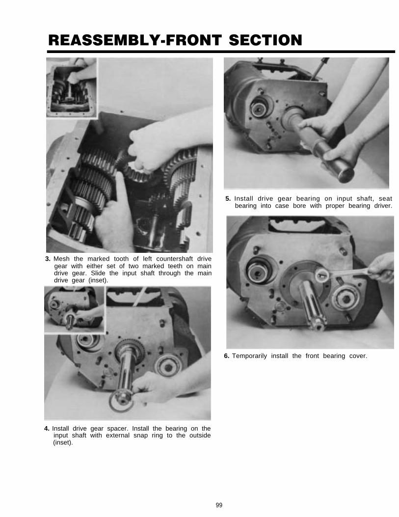
REASSEMBLY-FRONT SECTION
3. Mesh the marked tooth of left countershaft drivegear with either set of two marked teeth on maindrive gear. Slide the input shaft through the maindrive gear (inset).
5. Install drive gear bearing on input shaft, seatbearing into case bore with proper bearing driver.
6. Temporarily install the front bearing cover.
4. Install drive gear spacer. Install the bearing on theinput shaft with external snap ring to the outside(inset).
99

REASSEMBLY-FRONT SECTION. . .
7. Use a soft bar and maul to drive the input shaftthrough bearing. Remove front bearing cover.
9. Install front bearing cover and gasket, makingsure to align the oil return hole in the case withhole in cover. Secure the front bearing cover oncase with six capscrews, tighten to recommendedtorque (inset).
8. Install bearing retainer snap ring.
100

REASSEMBLY-FRONT SECTIONH. Reassembly and Partial Installation of
1.
2.
3.
Mainshaft AssemblyIf previously removed, install the correspondingsnap rings in I.D. of mainshaft gears.
Secure the mainshaft in a vise equipped withbrass jaws or wood blocks, pilot-end of shaftdown. If previously removed, install the roll pin inkeyway.
Install the 3rd speed gear limit washer on main-shaft, flat side of washer up. Rotate washer in the1st or bottom groove of mainshaft to align thesplines of washer with those of the mainshaft. in-stall the key in mainshaft keyway to lock washerin place.
4.
5.
Install the spacer on shaft against washer.
Install the 3rd speed gear on mainshaft, clutchingteeth down and engaged with external splines ofspacer.NOTE: Gear limit washers are internally splinedand locked to mainshaft by the key. Gear spacersare externally splined to engage with clutchingteeth in gear hubs. There is one limit washer andone spacer for each gear in the mainshaft as-sembly.
101

REASSEMBLY—FRONT SECTION
Setting Correct AxialClearances For MainshaftGears
Axial Clearance (End-Play) Limits Are:.005’’ -.012” for all mainshaft gears
Washers are used to obtain the correct limits; sixthicknesses are available as follows:
LIMITS (INCH) COLOR CODE
.248 -.250 WHITE
.253 -.255 GREEN
.258 -.260 ORANGE
.263 -.265 PURPLE
.268 -,270 YELLOW
.273 -.275 BLACK* “PLUS RED”
*NOTE: New style tolerance washers come in a fullrange of tolerances as corresponding colors listedabove “plus red.” (Example: “Orange plus red” limitwasher has an inch limit thickness of .258-.260.)
Refer to Illustrated Parts Lists for washer part num-bers.
Always use the .248 -.250 tolerance washer (“White”or “white plus red”) in the reverse, LO and 2nd speedgear positions as shown at right.
IMPORTANT: REFER TO THE APPROPRIATEILLUSTRATED PARTS LIST(SPECIFIED BY MODEL SE-RIES) TO ENSURE THATPROPER PARTS ARE USEDDURING REASSEMBLY OF THETRANSMISSION.
102

REASSEMBLY-FRONT SECTION
6. Install the 2nd speed gear on shaft against 3rdspeed gear, clutching teeth up.
7. Install the spacer in 2nd speed gear, engaging theexternal splines of spacer with clutching teeth ofgear.
8. Remove the key from keyway and install the 2ndspeed gear limit washer on mainshaft, flat side ofwasher down and against spacer. Rotate washer inthe 2nd groove of mainshaft to align the splines ofwasher with those of the mainshaft and reinsertkey in keyway to lock washer in place (inset).
9. Insert two large screwdrivers between the 2nd and3rd speed gears to check axial clearances. Applyslight downward pressure on screwdriver handlesto spread gears evenly. Making sure the gear hubsare parallel, insert a feeler gage between hubs.Correct axial clearance is less than the minimum.005" to .012" If the clearance is less than theminimum .005" tolerance, the limit washer in the2nd speed gear should be replaced by a thinnerlimit washer. This will increase the axial clearancebetween the gears. If the clearance checked isgreater than the maximum .012" tolerance, athicker limit washer should be installed in the 2ndspeed gear. This would decrease the axial clear-ance between the gears.
103

REASSEMBLY-FRONT SECTION
10. Install the 1st-2nd speed sliding clutch, aligningthe missing internal spline of sliding clutch withkey in mainshaft.
11. Remove the key from keyway and install the 1stspeed gear limit washer on mainshaft, flat side ofwasher up. Rotate washer in the 2nd groove ofmainshaft to align the splines of washer withthose of the mainshaft and reinsert key in key-way to lock washer in place.
12. Install spacer and 1st speed gear on the main-shaft, clutching teeth down and engaged with en-ternal splines of spacer.
13. Install the LO speed gear on shaft against 1stspeed gear, clutching teeth up.
104

REASSEMBLY-FRONT SECTION
14. Install the spacer in LO speed gear, engaging theexternal splines of spacer with clutching teeth of
16. Check axial clearances and make adjustments, ifnecessary, between the LO and 1st speed gearsas described in No. 9 of this section.
17. Install the LO-Reverse speed sliding clutch,aligning the missing internal spline of slidingclutch with key in mainshaft.
15. Remove the key from keyway and install the LOspeed gear limit washer on mainshaft, flat side ofwasher down and against spacer. Rotate washerin the 4th groove of mainshaft to align thesplines of washer with those of the mainshaftand reinsert key in keyway to lock washer inplace.
105

REASSEMBLY-FRONT SECTION
18.
19.
Remove the key from keyway and install the re-verse gear limit washer on mainshaft, flat side ofwasher up. Rotate washer in the 5th groove ofmainshaft to align the splines of washer withthose of the mainshaft and reinsert key in key-way to lock washer in place.
Install the spacer on shaft against washer.
20. Install reverse gear on mainshaft. Engage theclutching teeth of gear with splines of spacerand sliding clutch and move the reverse gearagainst the LO speed gear.
NOTE: DO NOT REPLACE REVERSE GEAR lN-TERNAL SNAP RING AT THIS STEP
21. Remove the mainshaft assembly from vise. Alignthe missing internal spline of 3rd-4th speed slid-ing clutch with key in mainshaft and install onfront of shaft, engaging the external splines ofsliding clutch with clutching teeth of 3rd speedgear.
106

REASSEMBLY-FRONT SECTION
22. Block the right countershaft assembly againstcase wall and lower the mainshaft assembly intoposition with the reverse gear held against LOspeed gear and rear of shaft moved into casebore.
23. Move the pilot-end of mainshaft into pocketbushing of input shaft.
.24. With the reverse gear remaining against LO
speed gear, mesh the corresponding forwardspeed gears of left countershaft assembly.Check to make sure that marked tooth on leftcountershaft drive gear has remained in meshwith marked set of teeth on main drive gear.
25. Center rear of mainshaft in case bore and installthe auxiliary drive gear assembly on shaft, par-tially seating the bearing in bore. DO NOT COM-PLETE INSTALLATION AT THIS TIME.
107

REASSEMBLY-FRONT SECTION. ñ -
1. Remove blocking from right countershaft a s -sembly and place it parallel to mainshaft as-sembly. Mesh the marked tooth of r ightcountershaft drive gear with remaining set of twomarked teeth on main drive gear.
2. Insert countershaft support tool or blocking inrear bearing bore.
3. Position the front countershaft bearing in frontbearing bore. Use the proper bearing driver to setthe bearing (inset).
4. Install retainer washer and capscrew. Make sureto match roll pin in retainer with inner bearing,hole.
108

REASSEMBLY - FRONT SECTION
5. Tighten capscrew to the recommended torque.
6. Position the countershaft rear bearing in rear bearingbore. Use the proper bearing driver to seat bearing inbore.
7. With bearing installation complete, install the snap ringin right countershaft rear groove.
8. Move the reverse gear to the rear on mainshaft and usea screwdriver to engage sliding clutches with all for-ward speed gears. A sliding clutch that will not engagewith a gear indicates the gear set is not in proper mesh.The bearings of the right countershaft would then needto be removed and the drive gear set retimed.
NOTE: Do not engage sliding clutches with more thanone gear at the same time. This will lock the gearingand prevent the mainshaft and countershaft assem-blies from rotating.
109

REASSEMBLY - FRONT SECTIONJ. Reassembly and Installation of Left
Reverse Idler Gear Assembly
NOTE: Since the left and right reverse idler gearassemblies are identical, reassembly and installation ofthe left reverse idler gear assembly should beperformed at this time as described in Part C of thissection.
K. Completed Installation of Mainshaftand Auxiliary Drive Gear Assemblies
3. Install the snap ring in hub of reverse gear and movethe reverse gear forward on mainshaft and into properposition in case.
1. Move the reverse gear to the rear as far as possible,meshing teeth of gear with those of the reverse idlergears.
4. Install snap ring on mainshaft snap ring groove.
2. Align the external splines of spacer with clutching teethof reverse gear and move spacer forward on themainshaft and into reverse gear.
5. Install splined washer on mainshaft splines behind re-verse gear.
110

REASSEMBLY - FRONT SECTION
6. Reinstall the front auxiliary drive gear assembly on rearof mainshaft. Use a flanged-end driver and maul to setbearing in case bore.
7. Align the six capscrew holes in retainer with the tappedholes in case and install capscrews. Tighten to recom-mended torque ratings and lockwire the capscrews ingroups of three.
8. Install splines washer on mainshaft splines behind aux-iliary drive gear.
9. Install the snap ring in groove at end of mainshaft.
111

INSTALLATION - CLUTCH HOUSING, OUTPUT YOKE,AUXILIARY SECTION AND SHIMMING PROCEDUREA. Installation of Clutch Housing
3. Install the six nuts with washers or lockwasherson studs and tighten. SEE TORQUE RECOMMEN-DATIONS.
4. For models so equipped, install the clutch releasemechanism and/or clutch brake assembly.
1. Position the corresponding new gasket on hous-ing mounting surface and install the clutch hous-ing on front case, piloting on the six studs andrive gear bearing cover.
2. Install the six capscrews with lockwashers andtighten. See TORQUE RECOMMENDATIONS.
112
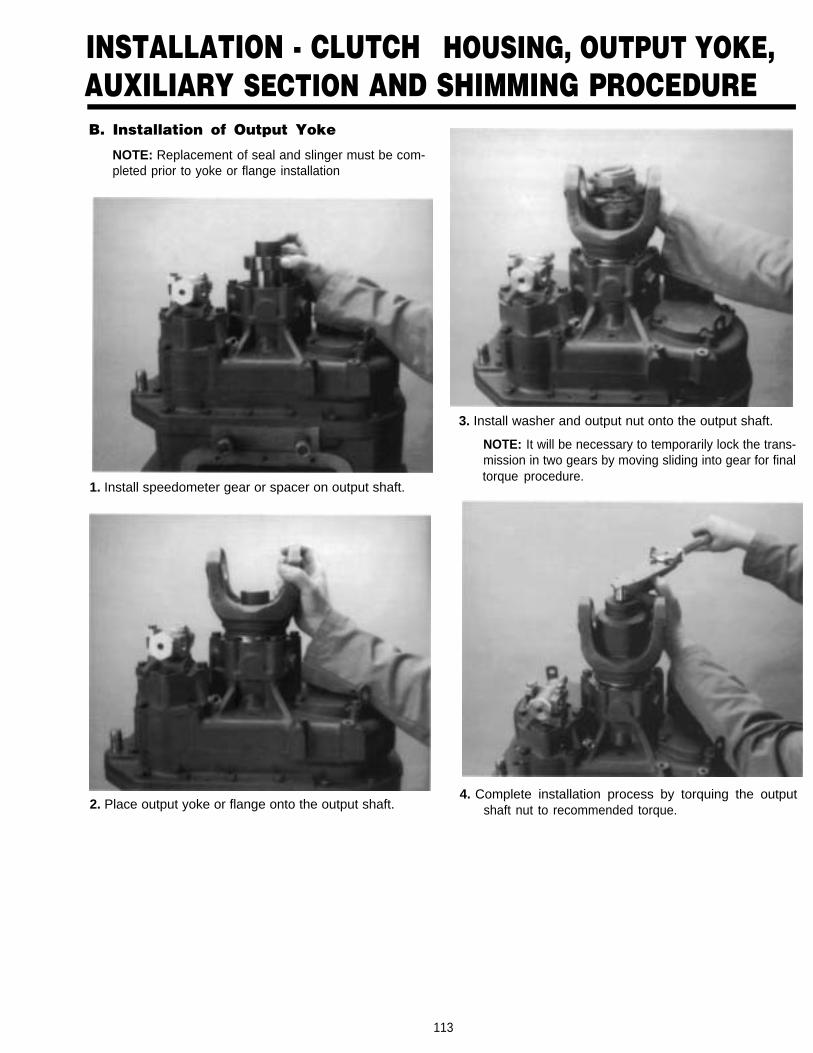
INSTALLATION - CLUTCH HOUSING, OUTPUT YOKE,AUXILIARY SECTION AND SHIMMING PROCEDUREB. Installation of Output Yoke
NOTE: Replacement of seal and slinger must be com-pleted prior to yoke or flange installation
1. Install speedometer gear or spacer on output shaft.
2. Place output yoke or flange onto the output shaft.
3. Install washer and output nut onto the output shaft.
NOTE: It will be necessary to temporarily lock the trans-mission in two gears by moving sliding into gear for finaltorque procedure.
4. Complete installation process by torquing the outputshaft nut to recommended torque.
113

INSTALLATION - CLUTCH HOUSING, OUTPUT YOKE,AUXILIARY SECTION AND SHIMMING PROCEDURE
Installation of the Auxiliary Sectionand Shimming Procedure
Tighten the middle bolt on each countershaft strap untilthe countershaft are snug. Shift the reduction slidingclutch into reduction. Attach a chain hoist to the outputshaft.
NOTE: The front box sliding clutches must be in theneutral position.
4. Remove the countershaft straps. Make sure a 0.125countershaft rear bearing shim is installed. Be sure thecountershaft rear bearing races are seated in the bear-ing bores.
2. With the transmission set in the vertical position, blockunder the clutch housing to prevent damage to theinput shaft, position the new gasket on the transmissioncase. Lower the auxiliary assembly on the front caserear.
IMPORTANT: Shift the reduction sliding clutch intodeep reduction before installing the auxiliary.
15. Install two clean 3/8" x 1" capscrews without washersdirectly across from each other in easy bearing cover.Tapped holes in auxiliary case must be free of threadadhesive.
3. Install the retaining capscrews in the housing flangeand tighten to the recommended torque.
114●

INSTALLATION - CLUTCH HOUSING, OUTPUT YOKE,AUXILIARY SECTION AND SHIMMING PROCEDURE
6. Tighten the capscrews to 7 in./lbs. of torque. DO NOTINSTALL THE COUNTERSHAFT REAR BEARINGCOVER GASKET.
7. Rotate the output shaft six times in the clockwise direc-tion, then six times counterclockwise to seat the coun-tershaft rear bearings. Use a feeler gauge, as close toone capscrew location as possible, and measure thegap between the countershaft rear bearing cover andthe auxiliary case. Record the measurement. Using theaverage measurement, refer to page 122 in this Ser-vice Manual. Select the numbers in the left column thatcompare to the average measurement recorded fromthe countershaft rear bearing cover. Follow the columnto the right to identify the proper shim to be used in thecountershaft shim bores. Duplicate this procedure forthe other countershaft rear bearing cover.
8. Remove the countershaft rear bearing covers andgauging shims.
9. After the correct shim has been selected, place theshim on the rear countershaft bearing race, install thecountershaft rear bearing cover and gasket. Check forproper shim alignment if misaligned rear bearing covermay be damaged when proper torque is applied. Posi-tion a new gasket on each countershaft rear bearingcover mounting surface and install both rear bearingcovers. Install and tighten the capscrews to the recom-mended torque.
115,

INSTALLATION-SHIFTING CONTROLSA. Installation Shift Bar Housing
1. Place all three mainshaft sliding clutches in the neutralposition. Install shift bar housing gasket in positionclutches.
2. With all three shift yokes in the neutral position, installthe shift bar housing assembly on case, fitting the shiftyokes into the slots of the corresponding slidingclutches.
3. Install the thirteen capscrews in shift bar housing andtighten to recommended torque rating.
NOTE: There are two sizes of capscrews. The 1/2"capscrews are used with lifting eyes.
116

INSTALLATION-SHIFTING CONTROLSGEAR SHIFT LEVER HOUSING ASSEMBLYB. Installation Gear Shift Lever Housing
Assembly
1. Check the shift bar housing assembly to make sure 2. Install the retaining capscrews in housing flange andtighten to secure the assembly to shift bar housing.shift block and yoke notches are aligned in the neutral
position.
117

INSTALLATION-SHIFTING CONTROLSC. Installation of Slave Valve
1. If previously removed, install the air line fittingson slave valve.
3. Install the hat-type alignment sleeve in bore ofslave valve.
2. Install the spring on shank of actuating pin and in-sert in bore of transmission case.
4. Position gasket on valve mounting surface (inset)and install the slave valve on case, inserting theend of actuating pin into alignment sleeve. Securethe valve to case with four capscrews tightenevenly to recommended torque rating.
118

INSTALLATION-SHIFTING CONTROLSD. Installation of Air Lines and Air Filter
Regulator
NOTE: Recommended sealant for fittings isFuller Sealant part number 71205.
1. Connect the 1/4" I.D. air hose between the slavevalve (inset) and the HI Range Port of the rangecylinder. Tighten fittings securely.
3. Position the air filter/regulator on the auxiliaryhousing rear and install the two retaining cap-screws. Tighten to recommended torque.
2. Connect the 1/4" I.D. air hose between the slavevalve (inset) and the LO Range Port of the rangecylinder. Tighten fittings securely.
4. Connect the 1/4" I.D. air hose between the slavevalve (inset) and the air filter/regulator. Tighten fit-tings securely.
119

INSTALLATION-SHIFTING CONTROLS
5. Connect the 1/4" I.D. air hose between the air filter/regulator (inset) and the splitter cylinder cover.Tighten fittings securely.
7. Install the jam nut on the shift lever. Thread theRoadranger valve on shift lever and secure bytightening jam nut against valve.
6. Install the Roadranger valve cover and the threeair lines.
8. Connect the red air line to the "S" or Supply Port, andthe black air line to the "P" or End Port of the slavevalve. Tighten fittings securely.
120

INSTALLATION-SHIFTING CONTROLS
9. Connect the red air line to the "S" or Supply Port andthe black air line to the "P" Port on the Roadrangervalve. Tighten fittings securely.
11. Position valve cover on Roadranger valve and se-cure by tightening the two mounting screws incover,
10. Connect the blue air line to the "SP" or Splitter Port onthe Roadranger valve (inset). Connect the blue air lineto the splitter cylinder cover. Tighten fittings securely.
121

SHIMMING CHARTAverage the feeler gauge measurement and match the measurement to the “Feeler Gauge Average Gap” in the left column.Follow the column to the right to identify the “Shim Thickness”, “Part Number”, and “Color Code” to be used.
FEELER GAUGE SHIM STANDARD SHIM OIL PUMP SHIM COLOR CODEAVERAGE GAP THICKNESS PART NUMBER PART NUMBER
.088-.089 .042-.043 21454 21474 BROWN
.085-.0875 .045-.046 21455 21475 TAN
.082-.0845 .048-.049 21456 21476 ORANGE
.079-.0815 .051-.052 21457 21477 YELLOW
.076.-0785 .054-.055 21458 21478 GREEN
.073.-0755 .057-.058 21459 21479 LIGHT BLUE
.070-.0725 .060-.061 21460 21480 LAVENDER
.067-.0695 .063-.064 21461 21481 WHITE
.064-.0665 .066-.067 21684 21686 BLACK
.061-.0635 .069-.070 21685 21687 SILVER
.058-.0605 .072-.074 21452+21452 21472+21472 RED+RED
.055-.0575 .075-.077 21452+21453 21472+21473 RED+PINK
.052-.-0545 .078+.080 21452+21454 21472+21474 RED+BROWN
.049-.0515 .081-.083 21452+21455 21474+21475 RED+TAN
.046-.0485 .084-.086 21452+21456 21472+21476 RED+ORANGE
.043-.0455 .087-.089 21452+21457 21472+21477 RED+YELLOW
.040-.0425 .090-.092 21452+21458 21472+21478 RED+GREEN
.038-.0395 .093-.095 21452+21459 21472+21479 RED+LT.BLUE
If the transmission is equipped with an auxiliary countershaft oil pump use the fourth column to identify the oil pump shim.
122

Copyright Eaton Corporation, 2012. Eaton hereby grant their customers, vendors, or distributors permission to freely copy, reproduce and/or distribute this document in printed format. It may be copied only in its entirety without any changes or modifications. THIS INFORMATION IS NOT INTENDED FOR SALE OR RESALE, AND THIS NOTICE MUST REMAIN ON ALL COPIES.
Note: Features and specifications listed in this document are subject to change without notice and represent the maximum capabilities of the software and products with all options installed. Although every attempt has been made to ensure the accuracy of information contained within, Eaton makes no representation about the completeness, correctness or accuracy and assumes no responsibility for any errors or omissions. Features and functionality may vary depending on selected options.
For spec’ing or service assistance, call 1-800-826-HELP (4357) or visit www.eaton.com/roadranger.In Mexico, call 001-800-826-4357.
Eaton CorporationVehicle GroupP.O. Box 4013Kalamazoo, MI 49003 USA800-826-HELP (4357)www.eaton.com/roadranger
Printed in USA
Roadranger: Eaton and trusted partners providing the best products and services in the industry, ensuring more time on the road.