Embed Size (px)
Citation preview
User Guide
Eaton Service Ranger Version 2TCMT0070A

Table of Contents
Welcome! 1
Introduction to ServiceRanger 2
ServiceRanger v2.8 2
Getting Started 3
Hardware Requirements 3
Communication Adapters 3
Getting Started with ServiceRanger 2 3
Connections to a vehicle 3
Starting ServiceRanger 4
Connecting 4
Features 5
Using ServiceRanger Overview 5
Main Functions of ServiceRanger 5
Vehicle Data Monitor 6
Monitor Data 6
Viewing Parameters 6
Display Options 7
Data Collection 8
Vehicle Fault Codes 11
Fault Codes 11
Clearing Fault Codes 13
Filtering Fault Codes 13
Product Downloads 14
Product Programming 14
AutoShift Gen1 15
VORAD EVT-300 22
Advanced Product Functions 30
Advanced Product Functions 30
VORAD Component Test 31
Utilities 41
Communication Settings 41
Check for Eaton Products 42
View Current Downloads 43
View Service Activity Report 43

Welcome!
Welcome!
ServiceRanger 2 is a PC-based electronic service diagnostic program that provides access to
your electronic Eaton AutoShift Gen1 and Bendix EVT-300 VORAD products. With Serv-
iceRanger 2, you can reduce downtime, save money, perform accurate repair procedures, all
while increasing productivity and profits.
The following are some of the major benefits of using ServiceRanger 2:
l View active and inactive diagnostic fault codes
l View data parameters in real time
l View the current configuration of a product
l Change product configurations
l Program (reflash) product software
1
Introduction to ServiceRanger
Introduction to ServiceRanger
ServiceRanger 2 is a PC software program developed by Eaton Corporation to diagnose and
service commercial vehicle components. ServiceRanger 2 is designed to communicate with
vehicle component controllers via the vehicle's diagnostic link connection. ServiceRanger 2
complies with the SAE Surface Vehicle Recommended Practices for J1587 vehicle com-
munications, as well as the TMC RP1210 PC communications standard developed for vehicle
link adapter communications.
ServiceRanger v2.8
ServiceRanger v2.8 edition is intended to be a final replacement for all ServiceRanger 2.x ver-
sions. No support services will be offered other than this online self help and user's manual. In
addition, there is no need to activate the software or connect to the Internet to receive soft-
ware updates.
If you are familiar with previous versions of ServiceRanger 2.x, there are some important
changes you should be aware of in this version. First, ServiceRanger 2.8 comes with the latest
product software and available configurations preloaded and the Internet download process to
receive product updates and configurations is no longer needed. Second, existing support for
AutoShift Gen2, AutoShift Gen3, and Lightning have been removed. You will need to use Serv-
iceRanger 3.x or newer to support these products.
The following Roadranger products are supported:
l Eaton AutoShift Gen1 Transmissions
l Bendix VORAD EVT-300 Collision Warning System
Notes:
l You will need to use ServiceRanger 3 or newer for servicing these products.
l Eaton AutoShift Gen2 Transmissions
l Eaton Lightning Transmissions
l Eaton AutoShift/UltraShift Gen3 Transmissions
l Eaton UltraShift Plus Transmissions
l Eaton Hybrid Electric System
l Future Eaton products
2
Getting Started
Getting Started
Hardware Requirements
In order to successfully install and run ServiceRanger 2, your PC shouldmeet the following
hardware requirements:
l Platform: IBM or 100% Compatible
l Operating System (32 bit versions):
l Windows 95™
l Windows 98™
l Windows XP™
l Processor: 500 MHz or greater
l RAM Memory: 128 MB or greater
l Hard Drive: 40 GB or greater
l Display: SVGA(800 x 600 pixels) Color
In addition, the PCmust also meet the hardware requirements for your communication
adapter. For more information about the communication adapter hardware requirements,
Please contact the communication adapter manufacturer.
Note:
l Minimum hardware will limit performance. For optimal performance use the rec-
ommended hardware or better.
l When installing ServiceRanger 2, you must have Windows Admin User permissions to
install, run, and update software on your computer. If you are unsure about your user
permissions, consult with your organization's computer support personnel before install-
ing this software.
Communication Adapters
ServiceRanger 2 complies with the SAE Surface Vehicle Recommended Practices for J1587
vehicle communications, as well as the RP1210A communication standards as defined by the
Truck Maintenance Council (TMC) for vehicle link adapter communications.
ServiceRanger 2 requires a vehicle adapter that is RP1210A compliant and has device drivers
that are compatible with the computer's operating system and external communications ports
(ie: USB, Serial, etc). Contact your communication adapter manufacture for information on
driver installation, as well as operating system and ServiceRanger 2 compatibility questions.
In addition, application downloads for AutoShift Gen1 involve a special programming harness
and communication adapter. The communication adapter must be a standard RS232 adapter
or a Dearborn DPA II RP1210A adapter with pass-through option. The special programming
harness is available from Eaton.
Getting Started with ServiceRanger 2
Connections to a vehicle
Before connecting to the vehicle with ServiceRanger 2make sure the communication adapter
is properly connected to the vehicle's diagnostic connector and to the computer's com-
munication port (i.e. USB, Comm1, etc). Turn the vehicle's ignition key to the on position and
3
Getting Started
verify the communications adapter is powered. If the adapter does not have a power indicator
lamp it may be necessary to use a volt meter to verify the adapter is getting power from the
vehicle's diagnostic connector.
Starting ServiceRanger
Once the communications adapter is properly connected to the vehicle and the PC, start Serv-
iceRanger by double clicking the ServiceRanger 2 shortcut icon located on the computer's desk-
top screen. You can also start ServiceRanger from the shortcut located in the Windows Start
programsmenu.
Connecting
Connect:When ServiceRanger has successfully started you may be promptedwith the option
to connect to a vehicle. Selecting the “Yes” button will automatically start vehicle com-
munications with the currently configured communication adapter, and load the Serv-
iceRanger main screen.
Work Offline: If the communication settings have not been configured or need to be
changed, it will be necessary to start ServiceRanger in the offline mode. Selecting the "No"
option will open ServiceRanger without connection to the vehicle.
4
Features
Features
Using ServiceRanger Overview
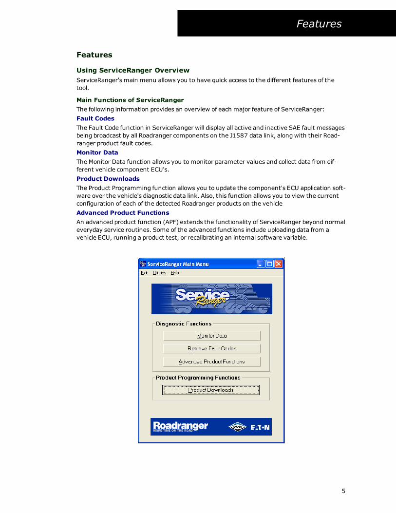
ServiceRanger's main menu allows you to have quick access to the different features of the
tool.
Main Functions of ServiceRanger
The following information provides an overview of each major feature of ServiceRanger:
Fault Codes
The Fault Code function in ServiceRanger will display all active and inactive SAE fault messages
being broadcast by all Roadranger components on the J1587 data link, alongwith their Road-
ranger product fault codes.
Monitor Data
The Monitor Data function allows you tomonitor parameter values and collect data from dif-
ferent vehicle component ECU's.
Product Downloads
The Product Programming function allows you to update the component's ECU application soft-
ware over the vehicle's diagnostic data link. Also, this function allows you to view the current
configuration of each of the detected Roadranger products on the vehicle
Advanced Product Functions
An advanced product function (APF) extends the functionality of ServiceRanger beyond normal
everyday service routines. Some of the advanced functions include uploading data from a
vehicle ECU, running a product test, or recalibrating an internal software variable.
5
Features
Vehicle Data Monitor
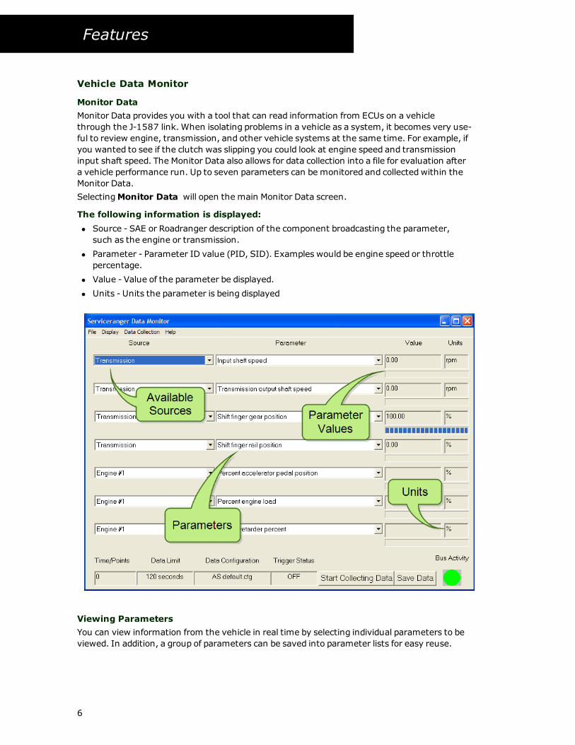
Monitor Data
Monitor Data provides you with a tool that can read information from ECUs on a vehicle
through the J-1587 link. When isolating problems in a vehicle as a system, it becomes very use-
ful to review engine, transmission, and other vehicle systems at the same time. For example, if
you wanted to see if the clutch was slipping you could look at engine speed and transmission
input shaft speed. The Monitor Data also allows for data collection into a file for evaluation after
a vehicle performance run. Up to seven parameters can be monitored and collected within the
Monitor Data.
SelectingMonitor Data will open the main Monitor Data screen.
The following information is displayed:
l Source - SAE or Roadranger description of the component broadcasting the parameter,
such as the engine or transmission.
l Parameter - Parameter ID value (PID, SID). Examples would be engine speed or throttle
percentage.
l Value - Value of the parameter be displayed.
l Units - Units the parameter is being displayed
Viewing Parameters
You can view information from the vehicle in real time by selecting individual parameters to be
viewed. In addition, a group of parameters can be saved into parameter lists for easy reuse.
6
Features
Viewing parameters
1. SelectMonitor Data.
2. After product detection, select Monitor Data parameter file.
3. To change source, select the drop down box and select the source description.
4. To change parameter, select the drop down box and select the source description.
5. The data parameter will be displayed.
Notes:
l When changing both source and parameter it is a good idea to select the source first and
then the parameter.
Parameter List
Once you have all the parameters you want to view selected, you can save the settings in a
configuration file for easy viewing at a later date.
Saving parameter list
1. Select parameters to be viewed.
2. Select File from the menu.
3. Select Save or Save as
l Save - Overwrites the currently open parameter list
l Save as - Enter name for parameter list and select Save.
4. The data parameter list will be saved.
Opening parameter list
1. Select File from the menu.
2. Select Open.
3. Select the parameter list name and select Open.
4. The data parameter list will be displayed in ServiceRanger.
Notes:
l Recent Files will pull up the last four parameter lists that were opened, allowing for quick
access to the most used parameter list files.
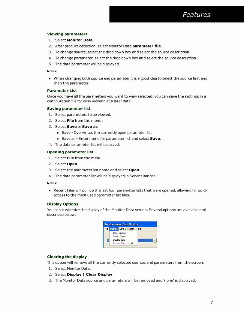
Display Options
You can customize the display of the Monitor Data screen. Several options are available and
described below.
Clearing the display
This option will remove all the currently selected sources and parameters from the screen.
1. Select Monitor Data.
2. Select Display | Clear Display.
3. The Monitor Data source and parameters will be removed and 'none' is displayed.
7
Features
Pausing the display
This option allows you to freeze the current values being displayed.
1. Select Monitor Data.
2. Select Display | Pause Display.
3. The Monitor Data parameters will stop updating their values and the sreen will be
grayed out.
Notes:
l After pausing the display, you can re-enable the display by selectingDisplay | Restart
Display.
Disabling bars
This option allows you to remove the data bars located below the values.
1. Select Monitor Data.
2. Select Display | Pause Display.
3. The Monitor Data parameters will stop updating their values and the data bars will be
grayed out.
Notes:
l After disabling the bars, you can re-enable the bars by selectingDisplay | Enable Bars.
Reduced source list
This option allows you to reduce the number of sources to those that are most commonly
installed on vehicles today.
1. Select Monitor Data.
2. Select Display | Reduced Source List.
3. The Monitor Data source list selection will be filtered or reduced to the most common
sources.
Notes:
l The source list is reduced to the following: Brakes Power Unit, Brakes Trailer #1, Trans-
mission, Collision Avoidance Radar, Engine, Axle Power Unit, Instrument Cluster, Vehicle
Management System, Communication Unit – Satellite, and Vehicle Logic Control Unit.
l To have the full sources listed once again, return to the display menu and click on Full
Source List.
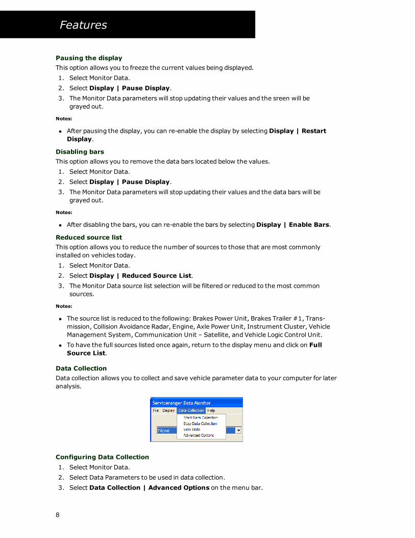
Data Collection
Data collection allows you to collect and save vehicle parameter data to your computer for later
analysis.
Configuring Data Collection
1. Select Monitor Data.
2. Select Data Parameters to be used in data collection.
3. Select Data Collection | Advanced Options on the menu bar.
8
Features
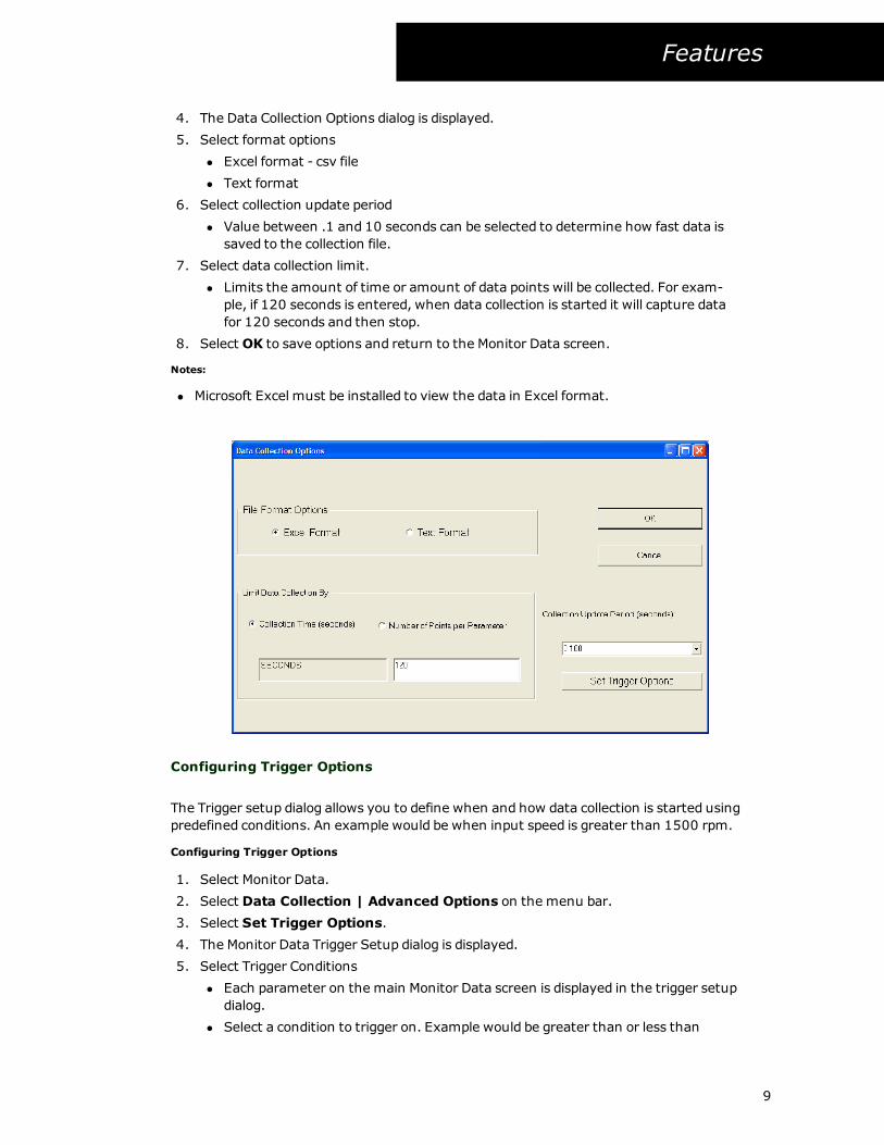
4. The Data Collection Options dialog is displayed.
5. Select format options
l Excel format - csv file
l Text format
6. Select collection update period
l Value between .1 and 10 seconds can be selected to determine how fast data is
saved to the collection file.
7. Select data collection limit.
l Limits the amount of time or amount of data points will be collected. For exam-
ple, if 120 seconds is entered, when data collection is started it will capture data
for 120 seconds and then stop.
8. Select OK to save options and return to the Monitor Data screen.
Notes:
l Microsoft Excel must be installed to view the data in Excel format.
Configuring Trigger Options
The Trigger setup dialog allows you to define when and how data collection is started using
predefined conditions. An example would be when input speed is greater than 1500 rpm.
Configuring Trigger Options
1. Select Monitor Data.
2. Select Data Collection | Advanced Options on the menu bar.
3. Select Set Trigger Options.
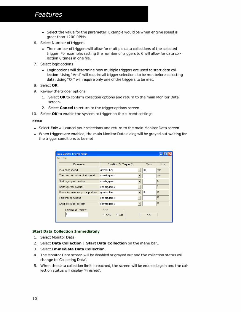
4. The Monitor Data Trigger Setup dialog is displayed.
5. Select Trigger Conditions
l Each parameter on the main Monitor Data screen is displayed in the trigger setup
dialog.
l Select a condition to trigger on. Example would be greater than or less than
9
Features
l Select the value for the parameter. Example would be when engine speed is
great than 1200 RPMs.
6. Select Number of triggers
l The number of triggers will allow for multiple data collections of the selected
trigger. For example, setting the number of triggers to 6 will allow for data col-
lection 6 times in one file.
7. Select logic options
l Logic options will determine how multiple triggers are used to start data col-
lection. Using “And” will require all trigger selections to be met before collecting
data. Using “Or” will require only one of the triggers to be met.
8. Select OK.
9. Review the trigger options
1. Select OK to confirm collection options and return to the main Monitor Data
screen.
2. Select Cancel to return to the trigger options screen.
10. Select OK to enable the system to trigger on the current settings.
Notes:
l Select Exitwill cancel your selections and return to the main Monitor Data screen.
l When triggers are enabled, the main Monitor Data dialog will be grayed out waiting for
the trigger conditions to be met.
Start Data Collection Immediately
1. Select Monitor Data.
2. Select Data Collection | Start Data Collection on the menu bar..
3. Select Immediate Data Collection.
4. The Monitor Data screen will be disabled or grayed out and the collection status will
change to 'Collecting Data'.
5. When the data collection limit is reached, the screen will be enabled again and the col-
lection status will display 'Finished'.
10
Features
Start Data Collection Using Triggers
1. Select Monitor Data.
2. Select Data Collection | Start Data Collection on the menu bar..
3. Select Immediate Data Collection.
4. Data collection is now 'armed' andwaiting for the trigger conditions to be met.
5. Once the trigger condition have been triggered, data will be collected until the selected
limit is reached, the screen will be enabled again and the collection status will display
'Finished'.
Stop Data Collection
Stop data collection is used to stop collecting data before the time or points limit has expired.
1. Select Monitor Data.
2. Select Data Collection | Stop Data Collection on the menu bar..
3. Data collection that is currently underway will be stopped.
View Data Collection
View data collection is used to view the data once it has been collected.
1. Select Monitor Data.
2. Select Data Collection | View Data on the menu bar.
3. Depending on the format options, the data collection file will be displayed in Microsoft
Excel or Word Pad.
l The source and parameter for the data is shown across the top of the file. The
data is shown in the columns below each source and parameter. The data has
two columns, the first column shows the actual time the data was received from
the communication link; the second column is the parameter data.
Notes:
l To save data simply perform a file “save as” function from Word Pad or Excel. If this is not
done the file will be overwritten by ServiceRanger the next time data is collected. Word
Pad and Excel must also be exited if data is to be collected again.
l When using triggers the row numbers will start over every time the trigger starts data
collection, allowing for data separation and analysis.
Vehicle Fault Codes
Fault Codes
The Fault Code function in ServiceRanger will display all active and inactive fault code mes-
sages being broadcast by components on the J1587 data link, alongwith their Roadranger prod-
uct fault codes.
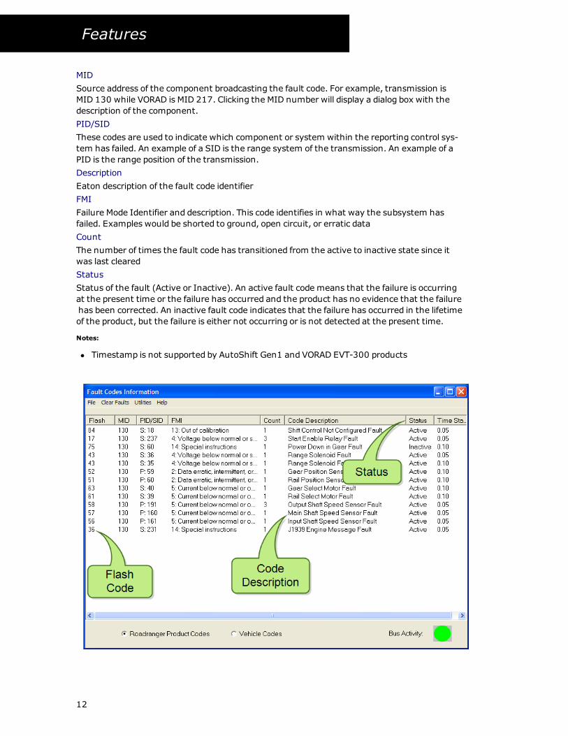
The following information is displayed:
Flash Code
The Eaton fault code assigned to the broadcasted fault message. ServiceRanger only displays
fault codes for supported products. This field is blank for unsupported components or unrec-
ognized fault messages.
11
Features
MID
Source address of the component broadcasting the fault code. For example, transmission is
MID 130 while VORAD is MID 217. Clicking the MID number will display a dialog box with the
description of the component.
PID/SID
These codes are used to indicate which component or system within the reporting control sys-
tem has failed. An example of a SID is the range system of the transmission. An example of a
PID is the range position of the transmission.
Description
Eaton description of the fault code identifier
FMI
Failure Mode Identifier and description. This code identifies in what way the subsystem has
failed. Examples would be shorted to ground, open circuit, or erratic data
Count
The number of times the fault code has transitioned from the active to inactive state since it
was last cleared
Status
Status of the fault (Active or Inactive). An active fault code means that the failure is occurring
at the present time or the failure has occurred and the product has no evidence that the failure
has been corrected. An inactive fault code indicates that the failure has occurred in the lifetime
of the product, but the failure is either not occurring or is not detected at the present time.
Notes:
l Timestamp is not supported by AutoShift Gen1 and VORAD EVT-300 products
12
Features
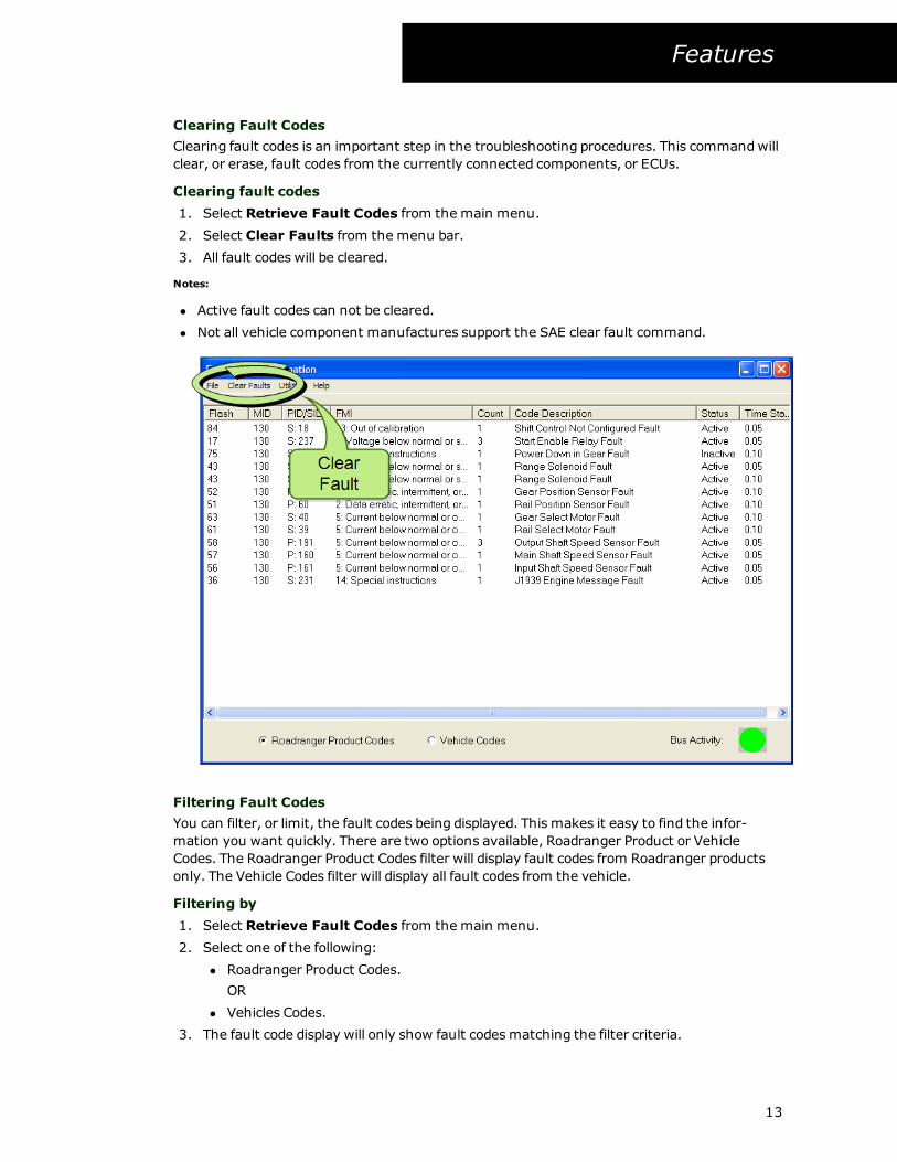
Clearing Fault Codes
Clearing fault codes is an important step in the troubleshooting procedures. This commandwill
clear, or erase, fault codes from the currently connected components, or ECUs.
Clearing fault codes
1. Select Retrieve Fault Codes from the main menu.
2. Select Clear Faults from the menu bar.
3. All fault codes will be cleared.
Notes:
l Active fault codes can not be cleared.
l Not all vehicle component manufactures support the SAE clear fault command.
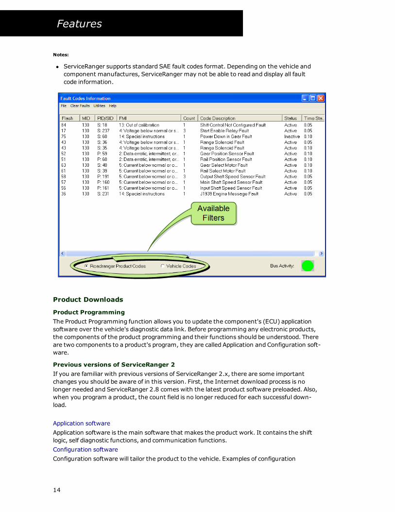
Filtering Fault Codes
You can filter, or limit, the fault codes being displayed. This makes it easy to find the infor-
mation you want quickly. There are two options available, Roadranger Product or Vehicle
Codes. The Roadranger Product Codes filter will display fault codes from Roadranger products
only. The Vehicle Codes filter will display all fault codes from the vehicle.
Filtering by
1. Select Retrieve Fault Codes from the main menu.
2. Select one of the following:
l Roadranger Product Codes.
OR
l Vehicles Codes.
3. The fault code display will only show fault codes matching the filter criteria.
13
Features
Notes:
l ServiceRanger supports standard SAE fault codes format. Depending on the vehicle and
component manufactures, ServiceRanger may not be able to read and display all fault
code information.
Product Downloads
Product Programming
The Product Programming function allows you to update the component's (ECU) application
software over the vehicle's diagnostic data link. Before programming any electronic products,
the components of the product programming and their functions should be understood. There
are two components to a product's program, they are called Application and Configuration soft-
ware.
Previous versions of ServiceRanger 2
If you are familiar with previous versions of ServiceRanger 2.x, there are some important
changes you should be aware of in this version. First, the Internet download process is no
longer needed and ServiceRanger 2.8 comes with the latest product software preloaded. Also,
when you program a product, the count field is no longer reduced for each successful down-
load.
Application software
Application software is the main software that makes the product work. It contains the shift
logic, self diagnostic functions, and communication functions.
Configuration software
Configuration software will tailor the product to the vehicle. Examples of configuration
14
Features
parameters are default start gear, maximum start gear, and shift points. Naturally, available
configurations will differ for each product.
There is typically an application program and a configuration program for each ECU on a prod-
uct. The Eaton AutoShift Gen1 series of transmissions has two controllers, therefore the Auto-
Shift will have two sets of software. One for the System Manager and another for the
Transmission Controller and each of which may needed to be updated.
It is important to only use a communications adapter that has been tested and
recommended by Eaton before attempting to program application software.
Some communication adapters, including some wireless models, are not well
suited for application software programming and could result in permanent dam-
age to the ECU.
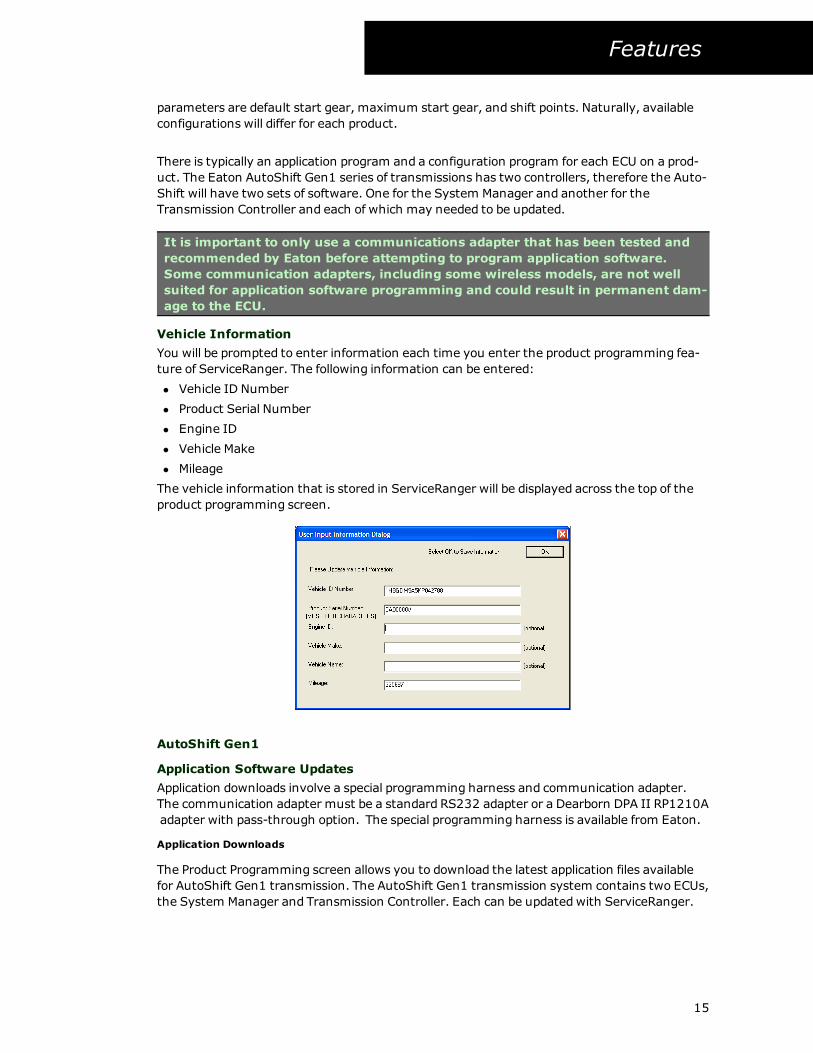
Vehicle Information
You will be prompted to enter information each time you enter the product programming fea-
ture of ServiceRanger. The following information can be entered:
l Vehicle ID Number
l Product Serial Number
l Engine ID
l Vehicle Make
l Mileage
The vehicle information that is stored in ServiceRanger will be displayed across the top of the
product programming screen.
AutoShift Gen1
Application Software Updates
Application downloads involve a special programming harness and communication adapter.
The communication adapter must be a standard RS232 adapter or a Dearborn DPA II RP1210A
adapter with pass-through option. The special programming harness is available from Eaton.
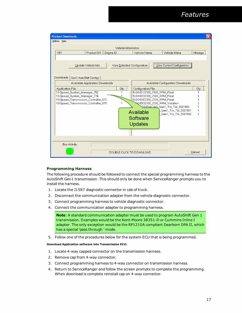
Application Downloads
The Product Programming screen allows you to download the latest application files available
for AutoShift Gen1 transmission. The AutoShift Gen1 transmission system contains two ECUs,
the System Manager and Transmission Controller. Each can be updatedwith ServiceRanger.
15
Features
Downloading Application Software Updates
1. Select Product Downloads.
2. Select AutoShift Gen1 product, if prompted.
3. If software updates are available, they will be displayed in the available application soft-
ware downloads window.
4. Select the application software update from the list and double click on the file name.
ServiceRanger will prepare the ECU for downloading.
5. ServiceRanger will display a warning screen prompting you to connect the pro-
gramming harness.
AutoShift GEN 1 products require a special programming harness and
communication adapter. For detailed information and instructions See
"Programming Harness" on page 17
6. When the programming harness and communication adapter are connected properly
click on theOK button (or select Cancel to return to the programming screen).
7. Select a either COM 1 or COM 2 communication port.
8. After selecting which communication port your communication adapter is connected,
click the OK button to begin a download. The download status will be shown by the
status bar located at the bottom of the screen.
9. When the download is complete ServiceRanger will prompt you to disconnect the spe-
cial programming harness and connect the communication adapter directly to the diag-
nostic connector.
10. It is also important to reset the transmission system after programming. You can do
this by turning the ignition key to the off position and letting the system power down.
Once power down is complete turn the ignition key to the on position. You will then
need to exit the programming function and then restart the programming function by
clicking on Product Downloads on the main menu.
Once a download is begun it cannot be canceled. The user must wait for the
download to be completed.
Notes:
l AutoShift transmission's have two ECU’s, a System Manager and a Transmission ECU.
Both of the ECU’s will be downloaded separately. The software is clearly marked to show
which software is for the Transmission Controller andwhich is for the System Manager.
l It is important that both the vehicle battery and computer power supply are fully
charged before attempting to update application software
l CTalk Initialization Error: ServiceRanger tried to connect to the ECU but did not receive a
return message. Most likely this is caused by faulty power or wiring problems. Recheck
the wiring to the ECU and try the download again.
l Ctalk Error Writing Data: ServiceRanger has connected to the ECU and tried to download
the software but an error occurred. The user should reset the transmission and try the
download again.
16
Features
Programming Harness
The following procedure should be followed to connect the special programming harness to the
AutoShift Gen1 transmission. This should only be done when ServiceRanger prompts you to
install the harness.
1. Locate the J1587 diagnostic connector in cab of truck.
2. Disconnect the communication adapter from the vehicle diagnostic connector.
3. Connect programming harness to vehicle diagnostic connector.
4. Connect the communication adapter to programming harness.
Note: A standard communication adapter must be used to program AutoShift Gen 1
transmission. Examples would be the Kent-Moore 38351-D or Cummins Inline I
adapter. The only exception would be the RP1210A compliant Dearborn DPA II, which
has a special 'pass through ' mode.
5. Follow one of the procedures below for the system ECU that is being programmed.
Download Application software into Transmission ECU:
1. Locate 4-way capped connector on the transmission harness.
2. Remove cap from 4-way connector.
3. Connect programming harness to 4-way connector on transmission harness.
4. Return to ServiceRanger and follow the screen prompts to complete the programming.
When download is complete reinstall cap on 4-way connector.
17
Features
Download Application software into System Manager ECU
1. Remove the shift tower's drivers side cover and locate the System Manager 32-way
connector.
2. Remove System Manager 32-way connector.
3. Connect programming harness to 32-way Adapter Harness.
4. Connect 32-way adapter harness to 32-way connector System Manager.
5. Return to ServiceRanger and follow the screen prompts to complete the programming.
6. When download is complete reconnect 32-way connector and reinstall driver side cover
on shift tower.
Configuration Downloads
The configuration files for a AutoShift Gen I transmission follow a 'B-number" format, which
has been used in the Direct Ship parts book for determining configurations required for
vehicles. With this format, one file gets downloaded to the transmission but has several dif-
ferent configuration parameters compiled in to it. Examples would be default start gear,
engine governed speed. etc. You can select standard or build a custom file with in Serv-
iceRanger. For more information on B-number, See "B-number Format" on page 21
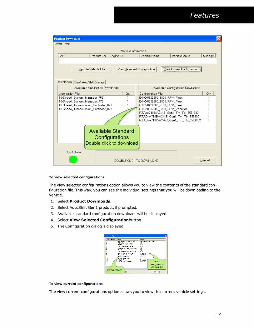
To Download a standard configuration
Standard configuration files are intended to fit most vehicles and vocations. This allows you
quick and easy access to fit most uses. You can choose from list provided or create a custom
configuration.
1. Select Product Downloads.
2. Select AutoShift Gen1 product, if prompted.
3. Available standard configuration downloads will be displayed.
4. Select the configuration option from the list and double click on the file name.
If you want to review the details of the standard configuration file, select
the file name and then select View Selected Configurations.
5. ServiceRanger will start to download andwill indicate its progress with the status bar at
the bottom of the screen.
6. After the download, ServiceRanger will request information from the product and
update the view Current Configuration screen.
18
Features
To view selected configurations
The view selected configurations option allows you to view the contents of the standard con-
figuration file. This way, you can see the individual settings that you will be downloading to the
vehicle.
1. Select Product Downloads.
2. Select AutoShift Gen1 product, if prompted.
3. Available standard configuration downloads will be displayed.
4. Select View Selected Configurationbutton.
5. The Configuration dialog is displayed.
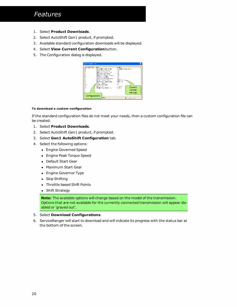
To view current configurations
The view current configurations option allows you to view the current vehicle settings.
19
Features
1. Select Product Downloads.
2. Select AutoShift Gen1 product, if prompted.
3. Available standard configuration downloads will be displayed.
4. Select View Current Configurationbutton.
5. The Configuration dialog is displayed.
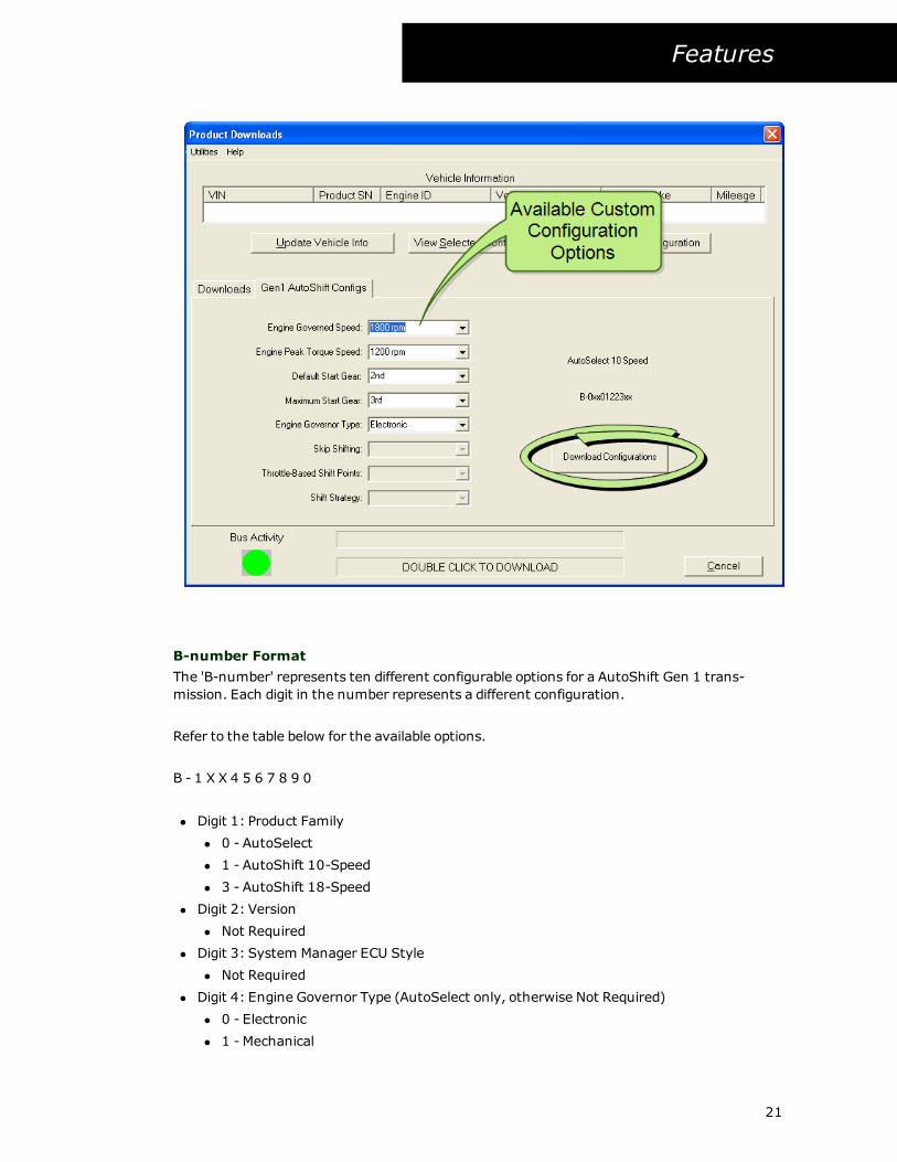
To download a custom configuration
If the standard configuration files do not meet your needs, then a custom configuration file can
be created.
1. Select Product Downloads.
2. Select AutoShift Gen1 product, if prompted.
3. Select Gen1 AutoShift Configuration tab.
4. Select the following options:
l Engine Governed Speed
l Engine Peak Torque Speed
l Default Start Gear
l Maximum Start Gear
l Engine Governor Type
l Skip Shifting
l Throttle based Shift Points
l Shift Strategy
Note: The available options will change based on the model of the transmission.
Options that are not available for the currently connected transmission will appear dis-
abled or 'grayed out'.
5. Select Download Configurations.
6. ServiceRanger will start to download andwill indicate its progress with the status bar at
the bottom of the screen.
20
Features
B-number Format
The 'B-number' represents ten different configurable options for a AutoShift Gen 1 trans-
mission. Each digit in the number represents a different configuration.
Refer to the table below for the available options.
B - 1 X X 4 5 6 7 8 9 0
l Digit 1: Product Family
l 0 - AutoSelect
l 1 - AutoShift 10-Speed
l 3 - AutoShift 18-Speed
l Digit 2: Version
l Not Required
l Digit 3: System Manager ECU Style
l Not Required
l Digit 4: Engine Governor Type (AutoSelect only, otherwise Not Required)
l 0 - Electronic
l 1 - Mechanical
21
Features
l Digit 5: Engine Governed Speed
l 0 - 1750 RPM
l 1 - 1800 RPM
l 2 - 1900 RPM
l 3 - 2000 RPM
l 4 - 2100 RPM
l 5 - 2200 RPM
l 6 - 2300 RPM
l 7 - 2400 RPM
l Digit 6: Engine Peak Torque RPM
l 0 - 1050 RPM
l 1 - 1100 RPM
l 2 - 1200 RPM
l 3 - 1300 RPM
l 4 - 1400 RPM
l Digit 7: Default Start Gear
l 1 - 1st Gear
l 2 - 2nd Gear
l 3 - 3rd Gear
l Digit 8: Maximum Starting Gear
l 1 - 1st Gear
l 2 - 2nd Gear
l 3 - 3rd Gear
l 4 - 4th Gear
l 5 - 5th Gear
l 6 - 6th Gear
l 7 - 7th Gear
l Digit 9: Skip Shifting (AutoShift 10-Speed only, otherwise Disabled)
l 0 - Enabled
l 1 - Disabled
l Digit 10: Throttle-Based Shift Points (AutoShift 10-Speed only, AutoSelect is Disabled)
l 1 - Enabled
l 0 - Disabled
l Digit 10: Shift Strategy (AutoShift 18-Speed only)
l 1 - Line Haul
l 0 - Vocational
VORAD EVT-300
VORAD Application Software Updates
The ServiceRanger Product Programming functions allows for convenient application software
changes to the EVT-300 VORAD system. ServiceRanger supports VORAD software version 106
and above.
22
Features
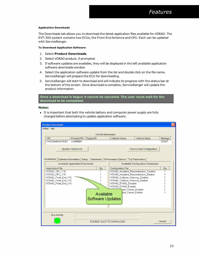
Application Downloads
The Downloads tab allows you to download the latest application files available for VORAD. The
EVT-300 system contains two ECUs, the Front End Antenna and CPU. Each can be updated
with ServiceRanger.
To Download Application Software
1. Select Product Downloads.
2. Select VORAD product, if prompted.
3. If software updates are available, they will be displayed in the left available application
software downloads window
4. Select the application software update from the list and double click on the file name.
ServiceRanger will prepare the ECU for downloading.
5. ServiceRanger will start to download andwill indicate its progress with the status bar at
the bottom of the screen. Once download is complete, ServiceRanger will update the
product information.
Once a download is begun it cannot be canceled. The user must wait for the
download to be completed.
Notes:
l It is important that both the vehicle battery and computer power supply are fully
charged before attempting to update application software.
23
Features
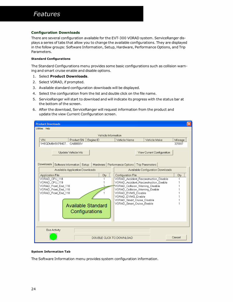
Configuration Downloads
There are several configuration available for the EVT-300 VORAD system. ServiceRanger dis-
plays a series of tabs that allow you to change the available configurations. They are displayed
in the follow groups: Software Information, Setup, Hardware, Performance Options, and Trip
Parameters.
Standard Configurations
The Standard Configurations menu provides some basic configurations such as collision warn-
ing and smart cruise enable and disable options.
1. Select Product Downloads.
2. Select VORAD, if prompted.
3. Available standard configuration downloads will be displayed.
4. Select the configuration from the list and double click on the file name.
5. ServiceRanger will start to download andwill indicate its progress with the status bar at
the bottom of the screen.
6. After the download, ServiceRanger will request information from the product and
update the view Current Configuration screen.
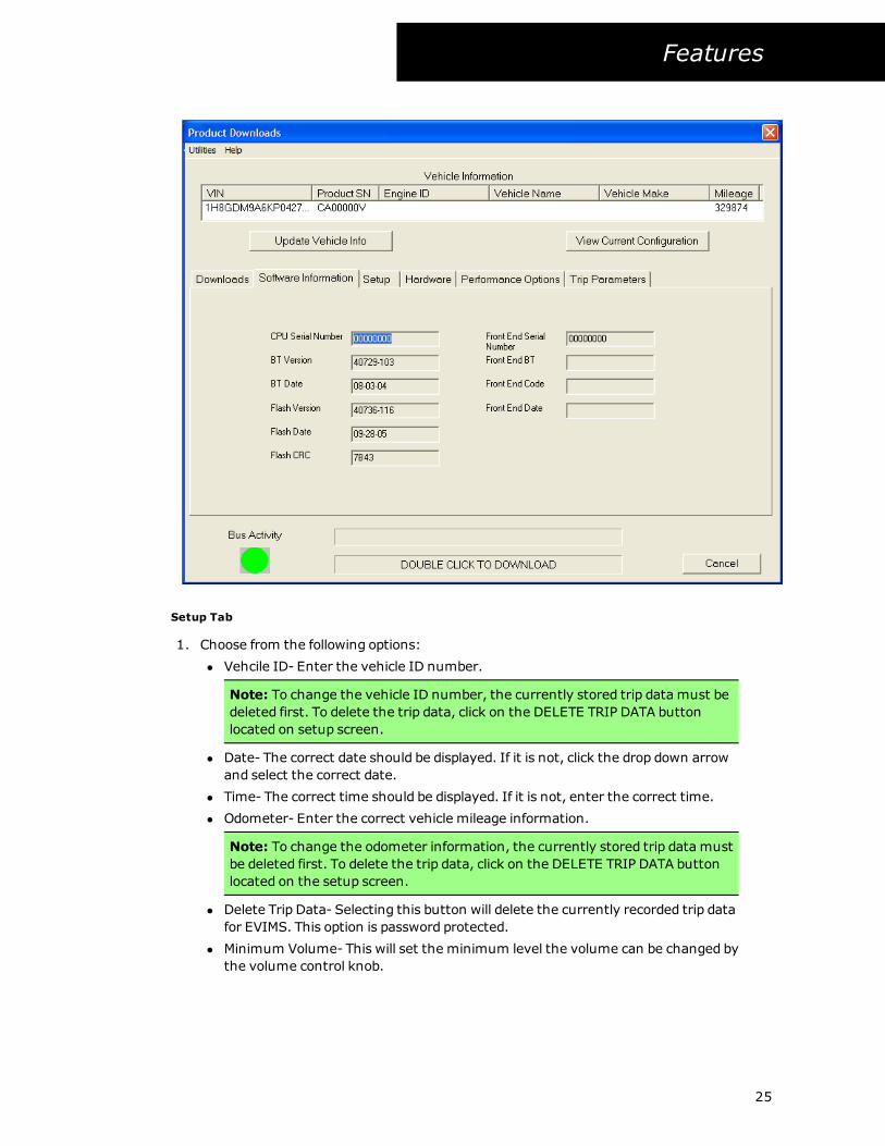
System Information Tab
The Software Information menu provides system configuration information.
24
Features
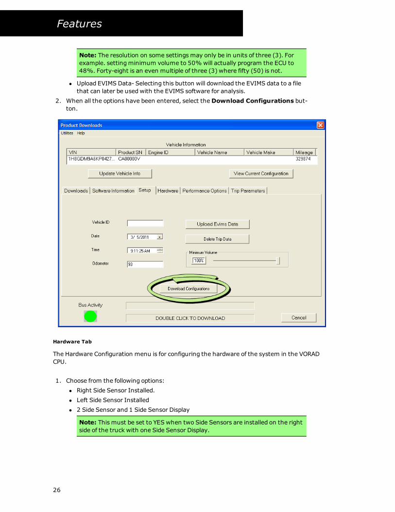
Setup Tab
1. Choose from the following options:
l Vehcile ID- Enter the vehicle ID number.
Note: To change the vehicle ID number, the currently stored trip data must be
deleted first. To delete the trip data, click on the DELETE TRIP DATA button
located on setup screen.
l Date- The correct date should be displayed. If it is not, click the drop down arrow
and select the correct date.
l Time- The correct time should be displayed. If it is not, enter the correct time.
l Odometer- Enter the correct vehicle mileage information.
Note: To change the odometer information, the currently stored trip data must
be deleted first. To delete the trip data, click on the DELETE TRIP DATA button
located on the setup screen.
l Delete Trip Data- Selecting this button will delete the currently recorded trip data
for EVIMS. This option is password protected.
l Minimum Volume- This will set the minimum level the volume can be changed by
the volume control knob.
25
Features
Note: The resolution on some settings may only be in units of three (3). For
example. settingminimum volume to 50% will actually program the ECU to
48%. Forty-eight is an even multiple of three (3) where fifty (50) is not.
l Upload EVIMS Data- Selecting this button will download the EVIMS data to a file
that can later be usedwith the EVIMS software for analysis.
2. When all the options have been entered, select theDownload Configurations but-
ton.
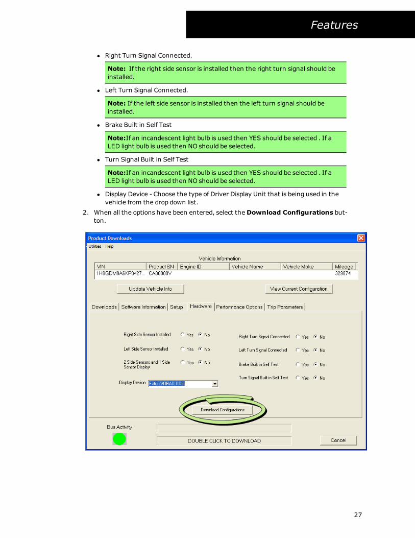
Hardware Tab
The Hardware Configuration menu is for configuring the hardware of the system in the VORAD
CPU.
1. Choose from the following options:
l Right Side Sensor Installed.
l Left Side Sensor Installed
l 2 Side Sensor and 1 Side Sensor Display
Note: This must be set to YES when two Side Sensors are installed on the right
side of the truck with one Side Sensor Display.
26
Features
l Right Turn Signal Connected.
Note: If the right side sensor is installed then the right turn signal should be
installed.
l Left Turn Signal Connected.
Note: If the left side sensor is installed then the left turn signal should be
installed.
l Brake Built in Self Test
Note:If an incandescent light bulb is used then YES should be selected . If a
LED light bulb is used then NO should be selected.
l Turn Signal Built in Self Test
Note:If an incandescent light bulb is used then YES should be selected . If a
LED light bulb is used then NO should be selected.
l Display Device - Choose the type of Driver Display Unit that is being used in the
vehicle from the drop down list.
2. When all the options have been entered, select theDownload Configurations but-
ton.
27
Features
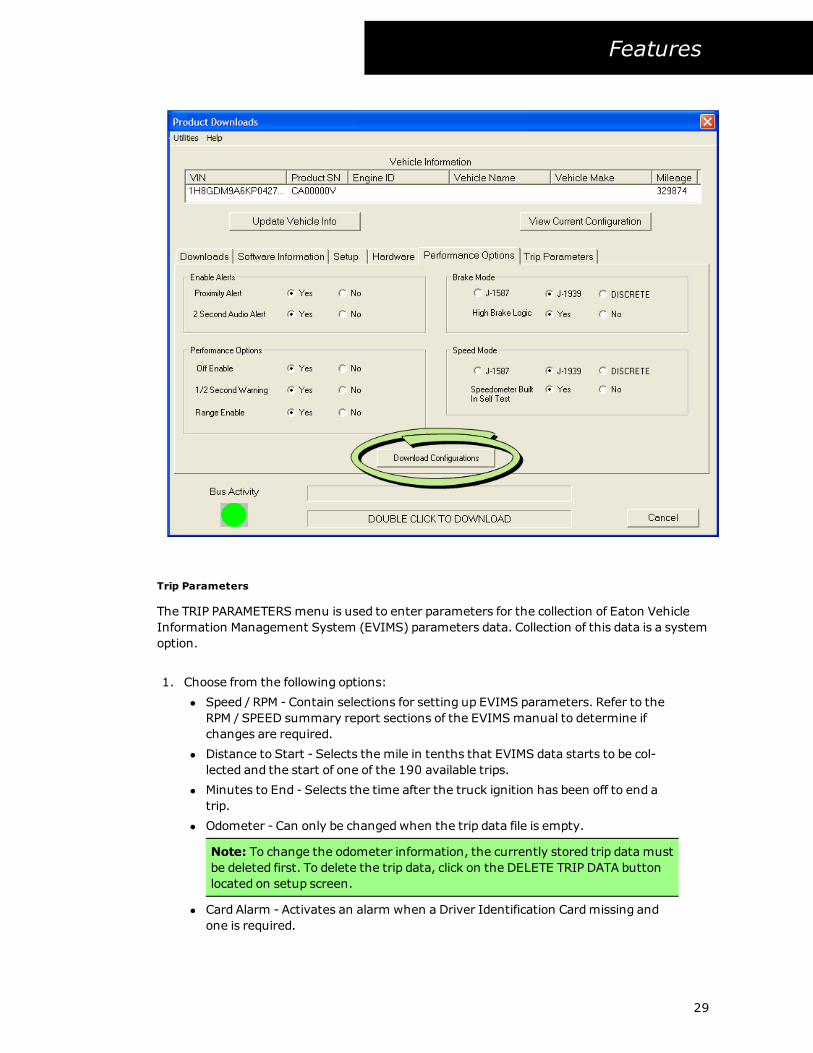
Performance Options Tab
This menu is used for selecting the correct system software operating parameters for the
installed system.
1. Choose from the following options:
l Brake Mode
l Brake Mode- Selects whether the input is discrete (a wired connection) or
data link signal.
l High Brake Logic- Selecting YES sets the CPU to sense applied voltage
when the brake pedal is pressed (applies only when using the discrete set-
ting).
l Enable Alerts
l Proximity Alerts- Selecting YES will detect when the truck is rolling towards
or away from an object, (the object needs to be less than 15 feet away, a
rate of more than 1/2 mph. and less than 2 mph.).
l 2 Second Audio Alert- Selecting YES will provides an audio alert when the
truck is within 2 seconds of the vehicle in front.
l 1/2 SecondWarning- Selecting YES will provide a continuous warning until
increasing the following distance.
l SpeedMode
l SpeedMode- Permits the selection of the speed source. This can be J1587,
J1939 or Discrete (a wired connection).
l Speedometer Built in Selft Test- Selecting YES will allow the CPU to verify a
speed source (applies only when using the discrete setting).
l Performance Options
l Off Enable- Selecting YES will allow the driver to turn the system off.
l Range Enable- Selecting YES will allow the driver to change the radar detec-
tion range with the display control knob.
2. When all the options have been entered, select theDownload Configurations but-
ton.
28
Features
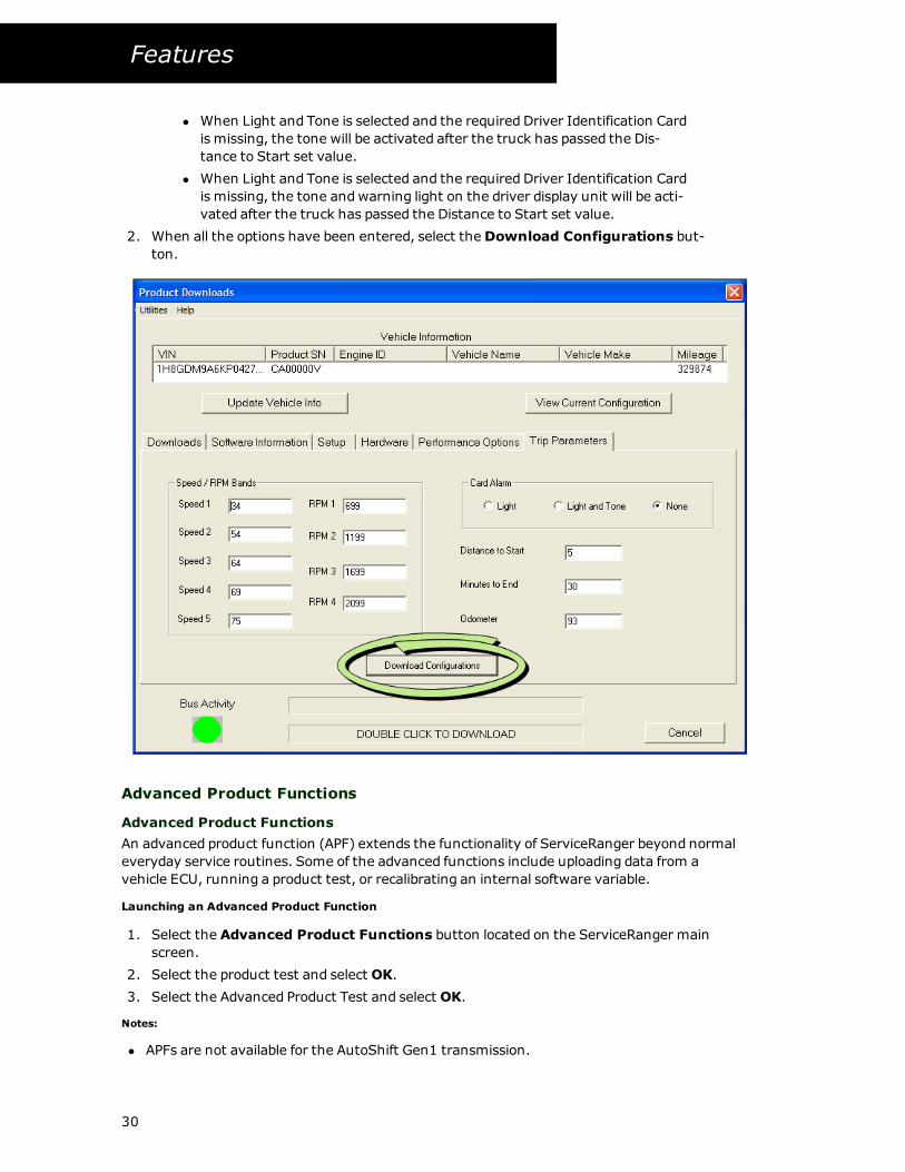
Trip Parameters
The TRIP PARAMETERSmenu is used to enter parameters for the collection of Eaton Vehicle
Information Management System (EVIMS) parameters data. Collection of this data is a system
option.
1. Choose from the following options:
l Speed / RPM - Contain selections for setting up EVIMS parameters. Refer to the
RPM / SPEED summary report sections of the EVIMSmanual to determine if
changes are required.
l Distance to Start - Selects the mile in tenths that EVIMS data starts to be col-
lected and the start of one of the 190 available trips.
l Minutes to End - Selects the time after the truck ignition has been off to end a
trip.
l Odometer - Can only be changedwhen the trip data file is empty.
Note: To change the odometer information, the currently stored trip data must
be deleted first. To delete the trip data, click on the DELETE TRIP DATA button
located on setup screen.
l Card Alarm - Activates an alarm when a Driver Identification Cardmissing and
one is required.
29
Features
l When Light and Tone is selected and the required Driver Identification Card
is missing, the tone will be activated after the truck has passed the Dis-
tance to Start set value.
l When Light and Tone is selected and the required Driver Identification Card
is missing, the tone andwarning light on the driver display unit will be acti-
vated after the truck has passed the Distance to Start set value.
2. When all the options have been entered, select theDownload Configurations but-
ton.
Advanced Product Functions
Advanced Product Functions
An advanced product function (APF) extends the functionality of ServiceRanger beyond normal
everyday service routines. Some of the advanced functions include uploading data from a
vehicle ECU, running a product test, or recalibrating an internal software variable.
Launching an Advanced Product Function
1. Select the Advanced Product Functions button located on the ServiceRanger main
screen.
2. Select the product test and select OK.
3. Select the Advanced Product Test and select OK.
Notes:
l APFs are not available for the AutoShift Gen1 transmission.
30
Features
VORAD Component Test
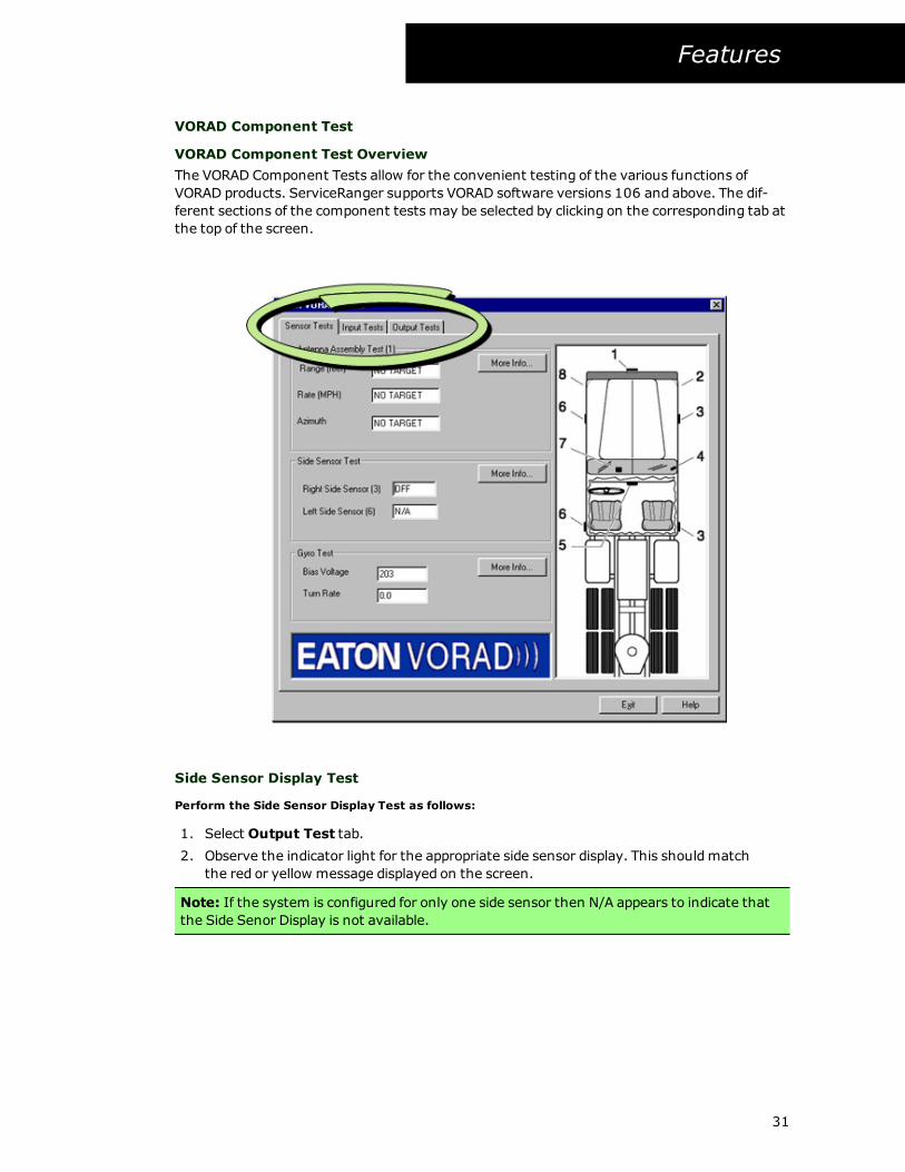
VORAD Component Test Overview
The VORAD Component Tests allow for the convenient testing of the various functions of
VORAD products. ServiceRanger supports VORAD software versions 106 and above. The dif-
ferent sections of the component tests may be selected by clicking on the corresponding tab at
the top of the screen.
Side Sensor Display Test
Perform the Side Sensor Display Test as follows:
1. Select Output Test tab.
2. Observe the indicator light for the appropriate side sensor display. This shouldmatch
the red or yellow message displayed on the screen.
Note: If the system is configured for only one side sensor then N/A appears to indicate that
the Side Senor Display is not available.
31
Features
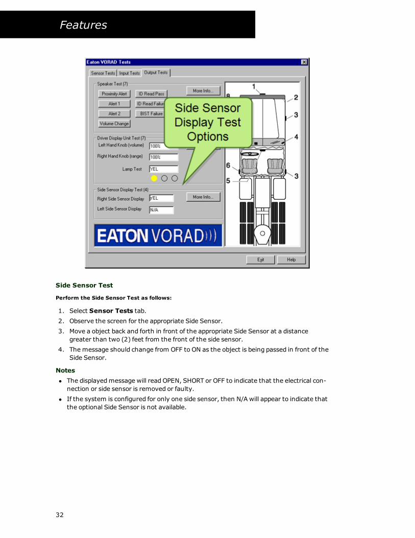
Side Sensor Test
Perform the Side Sensor Test as follows:
1. Select Sensor Tests tab.
2. Observe the screen for the appropriate Side Sensor.
3. Move a object back and forth in front of the appropriate Side Sensor at a distance
greater than two (2) feet from the front of the side sensor.
4. The message should change from OFF to ON as the object is being passed in front of the
Side Sensor.
Notes
l The displayedmessage will read OPEN, SHORT or OFF to indicate that the electrical con-
nection or side sensor is removed or faulty.
l If the system is configured for only one side sensor, then N/A will appear to indicate that
the optional Side Sensor is not available.
32
Features
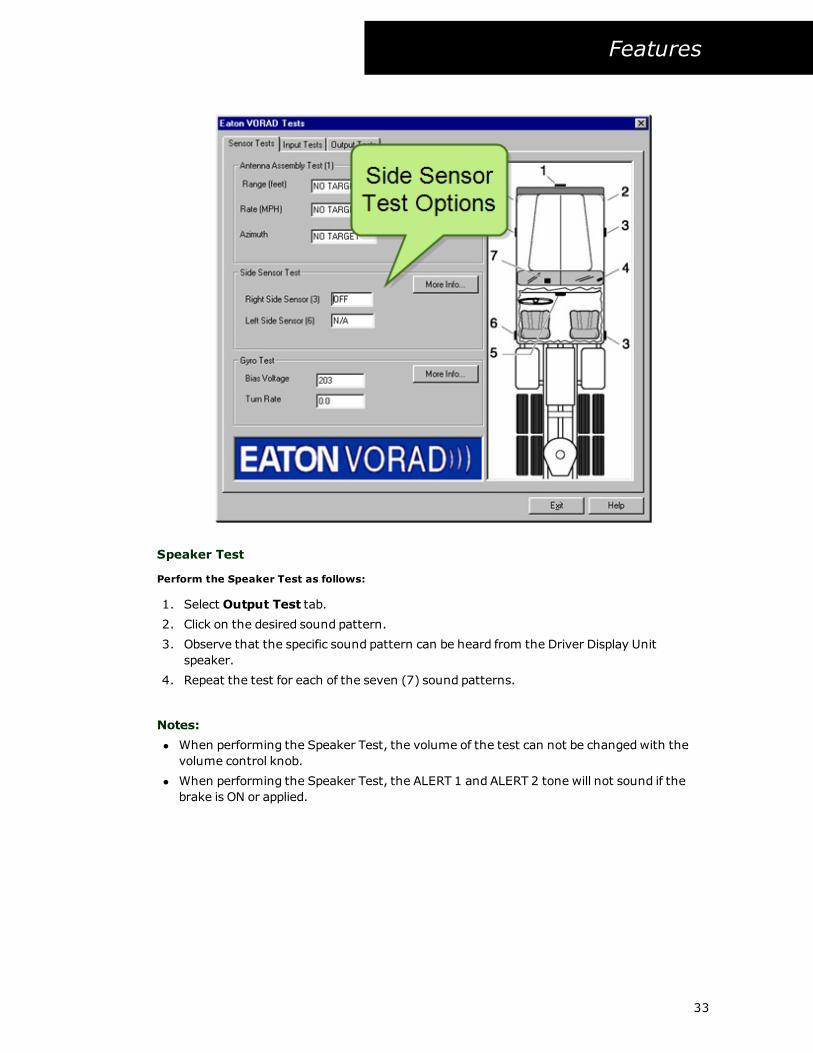
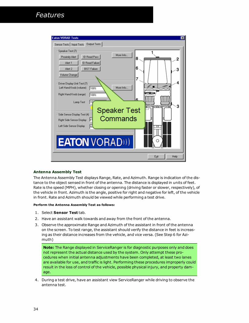
Speaker Test
Perform the Speaker Test as follows:
1. Select Output Test tab.
2. Click on the desired sound pattern.
3. Observe that the specific sound pattern can be heard from the Driver Display Unit
speaker.
4. Repeat the test for each of the seven (7) sound patterns.
Notes:
l When performing the Speaker Test, the volume of the test can not be changedwith the
volume control knob.
l When performing the Speaker Test, the ALERT 1 and ALERT 2 tone will not sound if the
brake is ON or applied.
33
Features
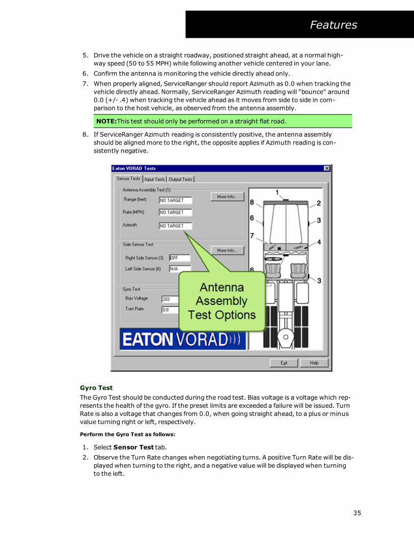
Antenna Assembly Test
The Antenna Assembly Test displays Range, Rate, and Azimuth. Range is indication of the dis-
tance to the object sensed in front of the antenna. The distance is displayed in units of feet.
Rate is the speed (MPH), whether closing or opening (driving faster or slower, respectively), of
the vehicle in front. Azimuth is the angle, positive for right and negative for left, of the vehicle
in front. Rate and Azimuth should be viewedwhile performing a test drive.
Perform the Antenna Assembly Test as follows:
1. Select Sensor Test tab.
2. Have an assistant walk towards and away from the front of the antenna.
3. Observe the approximate Range and Azimuth of the assistant in front of the antenna
on the screen. To test range, the assistant should verify the distance in feet is increas-
ing as their distance increases from the vehicle, and vice versa. (See Step 6 for Azi-
muth)
Note: The Range displayed in ServiceRanger is for diagnostic purposes only and does
not represent the actual distance used by the system. Only attempt these pro-
cedures when initial antenna adjustments have been completed, at least two lanes
are available for use, and traffic is light. Performing these procedures improperly could
result in the loss of control of the vehicle, possible physical injury, and property dam-
age.
4. During a test drive, have an assistant view ServiceRanger while driving to observe the
antenna test.
34
Features
5. Drive the vehicle on a straight roadway, positioned straight ahead, at a normal high-
way speed (50 to 55 MPH) while following another vehicle centered in your lane.
6. Confirm the antenna is monitoring the vehicle directly ahead only.
7. When properly aligned, ServiceRanger should report Azimuth as 0.0 when tracking the
vehicle directly ahead. Normally, ServiceRanger Azimuth reading will "bounce" around
0.0 (+/- .4) when tracking the vehicle ahead as it moves from side to side in com-
parison to the host vehicle, as observed from the antenna assembly.
NOTE:This test should only be performed on a straight flat road.
8. If ServiceRanger Azimuth reading is consistently positive, the antenna assembly
should be alignedmore to the right, the opposite applies if Azimuth reading is con-
sistently negative.
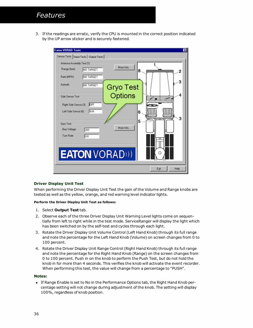
Gyro Test
The Gyro Test should be conducted during the road test. Bias voltage is a voltage which rep-
resents the health of the gyro. If the preset limits are exceeded a failure will be issued. Turn
Rate is also a voltage that changes from 0.0, when going straight ahead, to a plus or minus
value turning right or left, respectively.
Perform the Gyro Test as follows:
1. Select Sensor Test tab.
2. Observe the Turn Rate changes when negotiating turns. A positive Turn Rate will be dis-
playedwhen turning to the right, and a negative value will be displayedwhen turning
to the left.
35
Features
3. If the readings are erratic, verify the CPU is mounted in the correct position indicated
by the UP arrow sticker and is securely fastened.
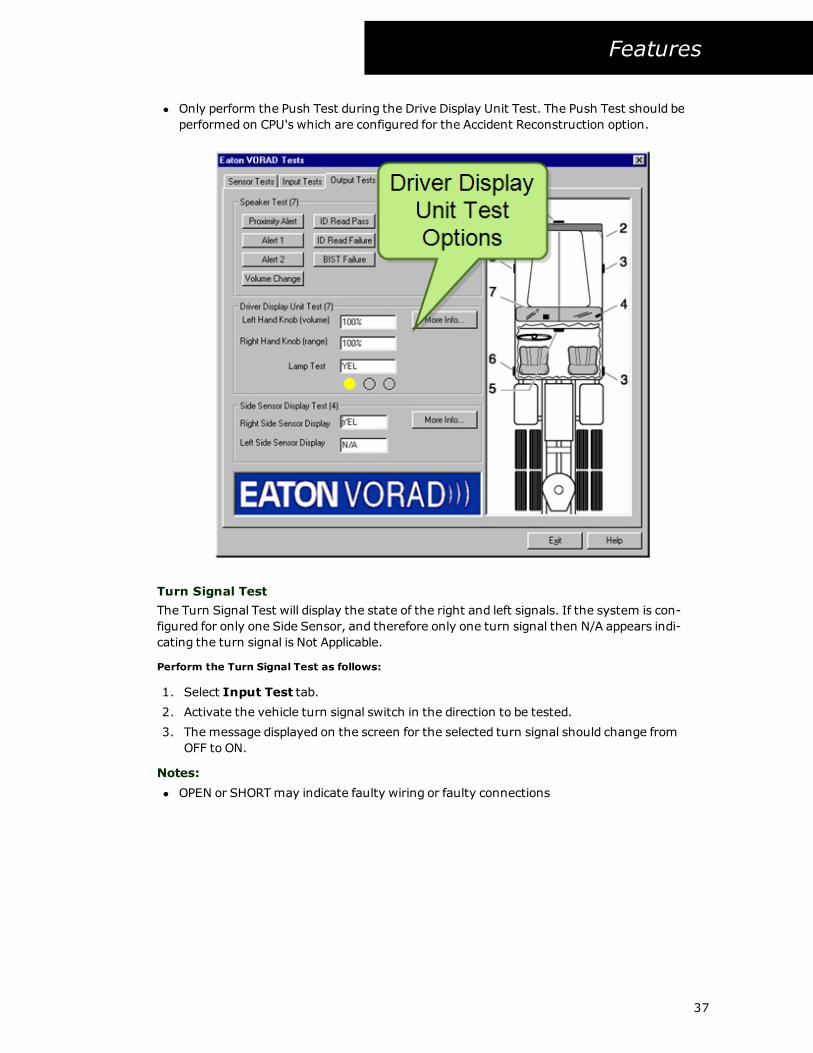
Driver Display Unit Test
When performing the Driver Display Unit Test the gain of the Volume and Range knobs are
tested as well as the yellow, orange, and redwarning level indicator lights.
Perform the Driver Display Unit Test as follows:
1. Select Output Test tab.
2. Observe each of the three Driver Display Unit Warning Level lights come on sequen-
tially from left to right while in the test mode. ServiceRanger will display the light which
has been switched on by the self-test and cycles through each light.
3. Rotate the Driver Display Unit Volume Control (Left Hand Knob) through its full range
and note the percentage for the Left Hand Knob (Volume) on screen changes from 0 to
100 percent.
4. Rotate the Driver Display Unit Range Control (Right Hand Knob) through its full range
and note the percentage for the Right Hand Knob (Range) on the screen changes from
0 to 100 percent. Push in on the knob to perform the Push Test, but do not hold the
knob in for more than 4 seconds. This verifies the knobwill activate the event recorder.
When performing this test, the value will change from a percentage to "PUSH".
Notes:
l If Range Enable is set to No in the Performance Options tab, the Right Hand Knob per-
centage setting will not change during adjustment of the knob. The setting will display
100%, regardless of knob position.
36
Features
l Only perform the Push Test during the Drive Display Unit Test. The Push Test should be
performed on CPU's which are configured for the Accident Reconstruction option.
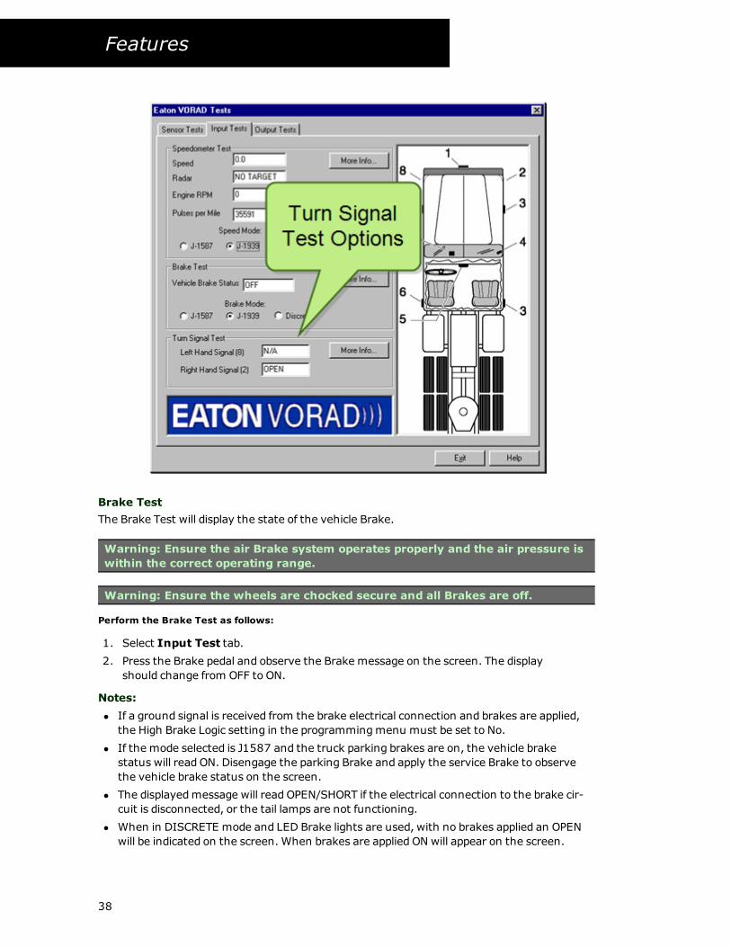
Turn Signal Test
The Turn Signal Test will display the state of the right and left signals. If the system is con-
figured for only one Side Sensor, and therefore only one turn signal then N/A appears indi-
cating the turn signal is Not Applicable.
Perform the Turn Signal Test as follows:
1. Select Input Test tab.
2. Activate the vehicle turn signal switch in the direction to be tested.
3. The message displayed on the screen for the selected turn signal should change from
OFF to ON.
Notes:
l OPEN or SHORTmay indicate faulty wiring or faulty connections
37
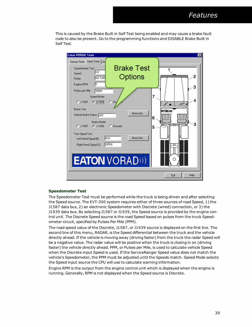
Features
Brake Test
The Brake Test will display the state of the vehicle Brake.
Warning: Ensure the air Brake system operates properly and the air pressure is
within the correct operating range.
Warning: Ensure the wheels are chocked secure and all Brakes are off.
Perform the Brake Test as follows:
1. Select Input Test tab.
2. Press the Brake pedal and observe the Brake message on the screen. The display
should change from OFF to ON.
Notes:
l If a ground signal is received from the brake electrical connection and brakes are applied,
the High Brake Logic setting in the programmingmenu must be set to No.
l If the mode selected is J1587 and the truck parking brakes are on, the vehicle brake
status will read ON. Disengage the parking Brake and apply the service Brake to observe
the vehicle brake status on the screen.
l The displayedmessage will read OPEN/SHORT if the electrical connection to the brake cir-
cuit is disconnected, or the tail lamps are not functioning.
l When in DISCRETE mode and LED Brake lights are used, with no brakes applied an OPEN
will be indicated on the screen.When brakes are applied ON will appear on the screen.
38
Features
This is caused by the Brake Built in Self Test being enabled andmay cause a brake fault
code to also be present. Go to the programming functions and DISABLE Brake Built in
Self Test.
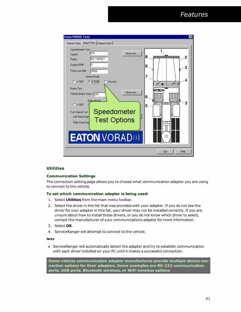
Speedometer Test
The Speedometer Test must be performedwhile the truck is being driven and after selecting
the Speed source. The EVT-300 system requires either of three sources of road Speed, 1) the
J1587 data bus, 2) an electronic Speedometer with Discrete (wired) connection, or 3) the
J1939 data bus. By selecting J1587 or J1939, the Speed source is provided by the engine con-
trol unit. The Discrete Speed source is the road Speed based on pulses from the truck Speed-
ometer circuit, specified by Pulses Per Mile (PPM).
The road speed value of the Discrete, J1587, or J1939 source is displayed on the first line. The
second line of this menu, RADAR, is the Speed differential between the truck and the vehicle
directly ahead. If the vehicle is moving away (driving faster) from the truck the radar Speedwill
be a negative value. The radar value will be positive when the truck is closing in on (driving
faster) the vehicle directly ahead. PPM, or Pulses per Mile, is used to calculate vehicle Speed
when the Discrete input Speed is used. If the ServiceRanger Speed value does not match the
vehicle's Speedometer, the PPMmust be adjusted until the Speedsmatch. SpeedMode selects
the Speed input source the CPU will use to calculate warning information.
Engine RPM is the output from the engine control unit which is displayedwhen the engine is
running. Generally, RPM is not displayedwhen the Speed source is Discrete.
39
Features
Warning: If the Speed input and/or source is incorrect, the EVT-300 will not pro-
vide accurate warnings.
Warning: Fault codes may be activated if improperly configured parameters are
used for Speed Mode.
Perform the Speedometer test as follows:
1. Select Input Tests tab.
2. Switch the selection of the SpeedMode by clicking in the appropriate radial button.
3. Changing the PPM is accomplished by selecting Discrete Mode. This will display a new
button. Change the number displayed in the Pulse Per Mile field on the screen and click
the Change PPM button.
Notes:
l The default value of 30,000 PPM will be accurate in most situation.
l On trucks equippedwith a mechanical (cable driven) Speedometer, the Discrete source
will be selected. A signal generator (also known as a tach gen)must be installed at the
transmission, in-line with the Speedometer cable.
l Signal Generators are not included in the EVT-300 system kit.
l For electronic Speedometers, a connection can be made to the wire which supplies the
Speedometer pulses (if the pulse is a square wave signal and does not interfere with the
operation of the Speedometer).
l The preferred Speedmode is the SAE J1587 or the J1939 data bus. When the J1587 or
J1939 data bus is used, PPM will not need to be changed.
40
Features
Utilities
Communication Settings
The connection setting page allows you to choose what communication adapter you are using
to connect to the vehicle.
To set which communication adapter is being used:
1. Select Utilities from the main menu toolbar.
2. Select the driver in the list that was providedwith your adapter. If you do not see the
driver for your adapter in this list, your driver may not be installed correctly. If you are
unsure about how to install these drivers, or you do not know which driver to select,
contact the manufacturer of your communications adapter for more information.
3. Select OK.
4. ServiceRanger will attempt to connect to the vehicle.
Note
l ServiceRanger will automatically detect the adapter and try to establish communication
with each driver installed on your PC until it makes a successful connection.
Some vehicle communication adapter manufactures provide multiple device con-
nection options for their adapters. Some examples are RS-232 communication
ports, USB ports, Bluetooth wireless, or WiFi wireless options
41
Features
Reset Communication
Reset communication will attempt to disconnect and reconnect from your vehicle com-
munication adapter. You should only attempt to use this command if you lost communication
with the vehicle or having other communication issues with the vehicle.
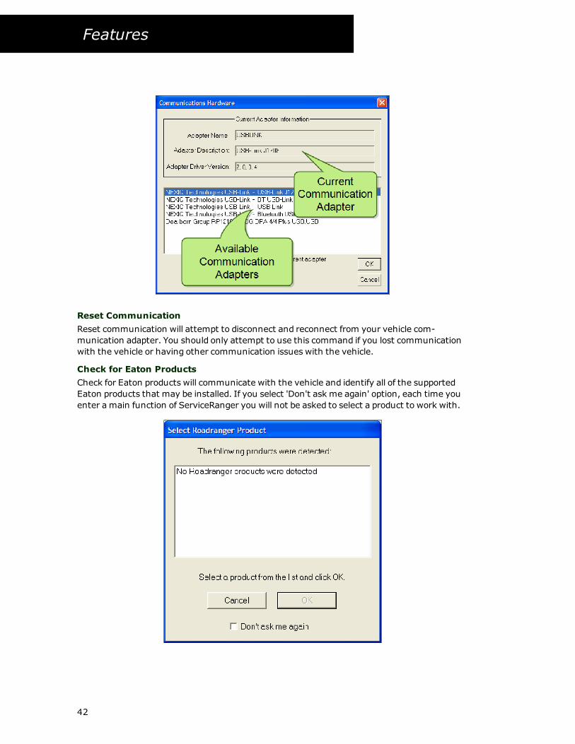
Check for Eaton Products
Check for Eaton products will communicate with the vehicle and identify all of the supported
Eaton products that may be installed. If you select 'Don't ask me again' option, each time you
enter a main function of ServiceRanger you will not be asked to select a product to work with.
42
Features
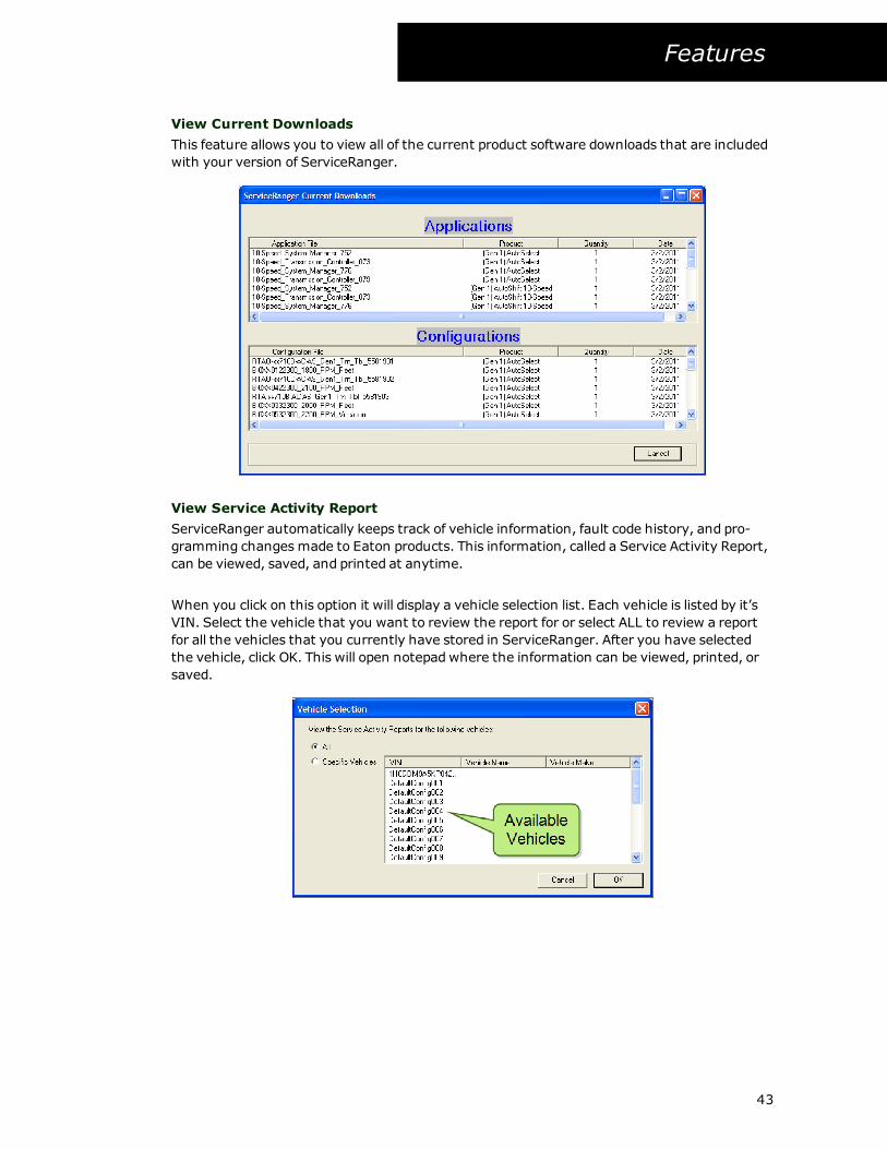
View Current Downloads
This feature allows you to view all of the current product software downloads that are included
with your version of ServiceRanger.
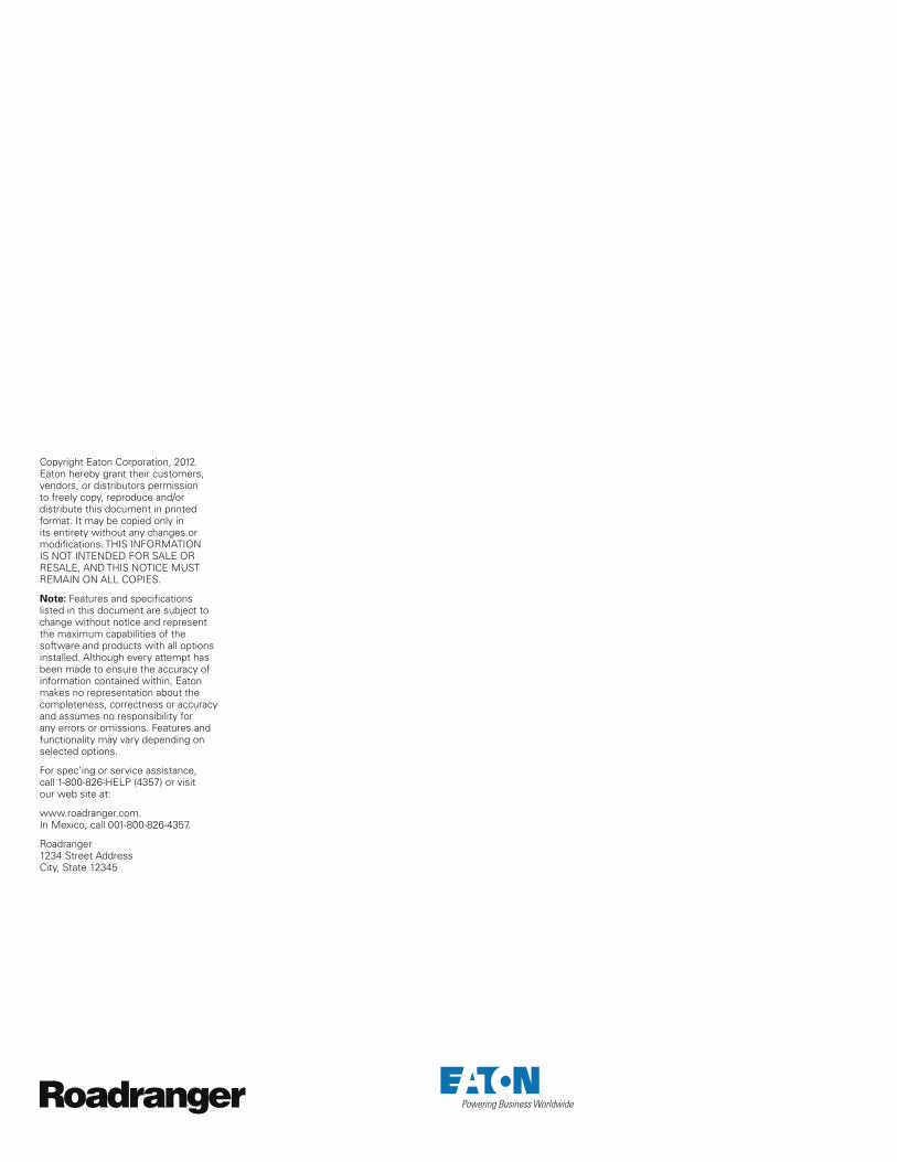
View Service Activity Report
ServiceRanger automatically keeps track of vehicle information, fault code history, and pro-
gramming changesmade to Eaton products. This information, called a Service Activity Report,
can be viewed, saved, and printed at anytime.
When you click on this option it will display a vehicle selection list. Each vehicle is listed by it’s
VIN. Select the vehicle that you want to review the report for or select ALL to review a report
for all the vehicles that you currently have stored in ServiceRanger. After you have selected
the vehicle, click OK. This will open notepadwhere the information can be viewed, printed, or
saved.
43


Copyright Eaton Corporation, 2012. Eaton hereby grant their customers, vendors, or distributors permission to freely copy, reproduce and/or distribute this document in printed format. It may be copied only in its entirety without any changes or modifications. THIS INFORMATION IS NOT INTENDED FOR SALE OR RESALE, AND THIS NOTICE MUST REMAIN ON ALL COPIES.
Note: Features and specifications listed in this document are subject to change without notice and represent the maximum capabilities of the software and products with all options installed. Although every attempt has been made to ensure the accuracy of information contained within, Eaton makes no representation about the completeness, correctness or accuracy and assumes no responsibility for any errors or omissions. Features and functionality may vary depending on selected options.
For spec’ing or service assistance, call 1-800-826-HELP (4357) or visit our web site at:
www.roadranger.com. In Mexico, call 001-800-826-4357.
Roadranger 1234 Street Address City, State 12345