Embed Size (px)
Citation preview

13th World Conference on Earthquake Engineering Vancouver, B.C., Canada
August 1-6, 2004 Paper No. 1543
FULL-SCALE LABORATORY TESTING OF BURIED POLYETHYLENE GAS DISTRIBUTION PIPELINES SUBJECT TO LATERAL GROUND
DISPLACEMENTS
Christopher ANDERSON1, Dharma WIJEWICKREME2, Carlos VENTURA3 and Allen MITCHELL4
SUMMARY A new full-scale testing facility has been developed to investigate soil-pipe interaction resulting from permanent ground deformations impacting buried piping networks. This paper presents a description of the capabilities of the new testing facility, and an insight into the response of branched buried polyethylene (PE) natural gas piping subject to permanent ground displacements. During ground movement, branched pipes are subjected to a complex interaction with soil, beginning as a lateral movement and transitioning to an axial pull out. The contributions from the branches to the pullout resistance of a trunk line can be approximated by the difference in pullout forces between the tests on branched and straight specimens. It appears that the performance of the branch is not significantly affected by the diameter of the trunk line. In smaller diameter trunk pipes, the trunk line is more vulnerable to damage than the branch, in contrast to the large diameter trunk pipes where the branched pipe is the most vulnerable during ground displacements. Arching of the surrounding soil, due to the reduction of pipe diameter combined with shear-induced soil volume changes during pullout, appears to result in reduced normal soil stresses acting against the pipe, and, in turn, resulting in decreased pullout resistance. In PE pipes, the axial displacement required for the mobilization of peak pullout resistance is significantly larger than those predicted using guidelines for the performance of steel pipelines. This is a direct result of the progressive failure that occurs at the soil-pipe interface in relatively flexible PE pipes.
INTRODUCTION The performance of buried natural gas pipeline systems in areas subjected to ground deformations is an important engineering consideration since geotechnical hazards can be a major cause of damage to these utilities. In a technical context, developing a detailed understanding of the associated soil-pipe interaction problem would be the key to developing the desired criteria or guidelines to address this problem.
1 Graduate Student, University of British Columbia, Vancouver, Canada. Email: [email protected] 2 Associate Professor, University of British Columbia, Vancouver, Canada. Email: [email protected] 3 Professor, University of British Columbia, Vancouver, Canada. 4 Project Manager, Engineering, Terasen Gas Inc., Surrey, Canada.

Although soil-pipe interaction models exist, there is only limited experience with pipeline materials other than steel, and in particular polyethylene (PE). With PE pipelines now becoming the industry standard for natural gas distribution systems, a detailed investigation into the interaction of these materials with the surrounding soil is needed to ensure that the response of both pipeline and soil components is properly understood during design. A relatively large body of work exists in the literature stemming from previous research in the area of soil/pipeline interaction for mid- to large-diameter steel transmission pipelines. The leading research facilities in this field have been Cornell University, reported by Traughtman [1,2], and more recently C-CORE, reported by Paulin [2]. Both facilities have made use of full-scale testing tanks to investigate the effects of axial, lateral and uplift loading on buried steel pipelines. The majority of the testing performed to date has investigated mid- to large-diameter steel pipelines, however, for small diameter pipelines, and particularly for polymer pipes, little if any research has been carried out. The relationships developed by these studies, in particular the work at Cornell University, has been subsequently adopted for the ASCE Committee on Gas and Liquid Fuel Lines Guidelines for the Seismic Design of Oil and Gas Pipeline Systems [4] and for the American Lifelines Alliance Guidelines for the Design of Buried Steel Pipe [5]. In test programs performed at other facilities, pipe strains and pressures have been routinely monitored. There have only been a few attempts to specify soil displacements as a measure of pipe failure criteria. This may be partly a result of the current limited understanding of the soil-pipeline interaction problem and the modeling approaches. The results of full-scale laboratory testing have begun to extend into field-based axial pullout tests, in which out of service or abandoned pipelines have been axially loaded to induce movement [6,7]. Only limited information regarding the results of these tests is available in the literature, as most of these tests have been performed for private agencies, the results of which are seldom published. The few results that are available, however, appear to be consistent with laboratory test results. Analytical models developed for soil-pipe interaction have primarily been derived from full-scale laboratory testing results. For the major pipeline design guidelines under consideration, ASCE and ALA, the pipeline is most often modeled as a structural beam, and soil-pipeline interaction is accounted for using simple design formulas applied to highly idealized conditions. The equations are generally modified versions of pile or soil anchor theoretical and analytical closed-form solutions. The bi-linear soil-spring representations have been commonly accepted as adequate for analysis. However, as observed in much of the literature, there are numerous discrepancies between laboratory tests and these simple equations. Further, as additional observations are made, it becomes apparent that additional micro- and macroscopic behaviour of soils such as strain softening and arching, as observed by Petroff [8], are not accounted for in the models. In order to review the performance of numerical tools for structural modeling, several researchers have compared numerical analysis with field data on slope movements and pipeline strain [9, 10]. These researchers have presented several case studies of numerical modeling performed for areas experiencing slow slope movements on the order of 1 to 10 mm per year. The researchers indicate that the accuracy of their numerical models was limited by the availability of an accurate physical model of soil-pipeline interaction and by an accurate representation of the slide front. With additional understanding of the slide mechanics and soil-pipeline interaction it appears likely that significant progress could be made in modeling pipeline networks. With this background, a detailed research program involving full-scale physical modeling has been undertaken at the University of British Columbia (UBC), Canada, in partnership with Terasen Gas Inc., BC, Canada, to study soil-pipeline interaction during permanent ground displacements affecting distribution networks of PE piping. The objectives of this research are to determine the contributing factors, and key parameters influencing the behaviour of polyethylene pipe buried in soil. While the work

stems from potential concerns in natural gas distribution areas where slow, continual ground movements such as “perpetual” slope creep are anticipated, the research findings as well as criteria and guidelines resulting from the observations are judged to be equally applicable to other forms of ground deformations, including those induced by earthquake liquefaction. This paper presents a description of the capabilities of the new testing facility at UBC and discusses the range of information obtainable from full-scale soil-pipeline interaction testing, using the results from the testing of branched-pipe configurations as an example.
EXPERIMENTAL PROGRAM Full-scale Testing Apparatus A testing apparatus, shown in Figure 1, has been designed and constructed specifically to meet the requirements for full-scale physical modeling research on pipe-soil interaction problems. The objectives of the research presented herein were to determine force-displacement and strain responses of polyethylene pipelines in sand subjected to axial loading in configurations typical of natural gas distribution networks. The new system allows the study of stress-strain and displacement responses of a variety of typical buried pipeline configurations subjected to axial and transverse soil loadings, corresponding to multiple in-situ conditions.
Figure 1: Testing Chamber Configuration for Axial Pullout Testing A soil box (up to 3m W x 5m L x 2m H) was designed for full-scale testing based on several criteria that were derived from consideration of both pipeline and soil deformation mechanisms [11]. The principal criteria governing the design of the box were:

• The length and width of the box should allow full development of active and passive soil
deformation zones in the vicinity of either the main portion or branched sections of pipe for sizes up to 500 mm;
• The size of the box should permit development of significant changes in strain with length
(stretching of the pipe) for axial pullout specimens, and should allow full development of bending strains over a reasonable length for sections of branched-pipe oriented perpendicular to pullout direction;
• The walls of the box should provide “rigid” boundary conditions; and
• The size and configuration of the box should be reasonably easily modified in order to meet
alternative test configurations. For the tests performed during the research, approximately 15 m3 of sand was required for each test to achieve the required depth of cover above the pipeline. Once the pipeline was configured for the test, an overhead crane was employed to lift sand storage bags into the chamber, where it was possible to spread the sand throughout the chamber by controlling the movement of the crane. For medium loose tests, the sand was slumped from the bottom chute of the bag to achieve a relatively low soil density; for tests on dense specimens, the sand was compacted using a vibratory plate tamper. The loading system for the tests required displacement-controlled movement of the pipe specimen through soil at very slow displacement rates in order to simulate the natural situation of landslide creep deformation. The pullout loading system consisted of a 225 kN (50 kip) capacity hydraulic cylinder, an analog control system, and a clamping arrangement that permits only uni-directional pipe displacement. Since the research is on the deformation of the pipeline segments, most of the instrumentation was focused on and around the pipelines. The pipeline instrumentation array is able to measure pullout forces, displacements of the ends of the pipe and of points along the pipe specimen buried in the soil, and strains within the pipe specimen. Point strains were measured at multiple locations along the main trunk of the pipeline and also along the branches using polymer-specific strain gauges. Further details on strain gauge selection, and specialized procedures for surface preparation and bonding to polyethylene as well as methods to protect strain gauges from abrasion during pipeline displacement can be found in Anderson [12]. The pipe displacements were monitored using string potentiometers mounted at specific points as desired. Test Materials The soil used for the testing program is locally obtained Fraser River sand, which has been extensively tested and documented during numerous laboratory research programs performed at UBC in the past. This soil was chosen in order to make use of the thorough understanding of the material properties with the purpose of providing a baseline for comparison. This fine to medium sand has an angle of internal friction reported in the literature of 32° loose and 38° dense. The average grain size, D50, is 0.23 mm, with a coefficient of uniformity, Cu of 1.5. The minimum particle size is 0.074 mm and minimum and maximum void ratios for the material are 0.68 and 1.00, respectively. The moisture content of the sand was allowed to stabilize at less than 1% moisture before the testing program began. The sand was kept in this dry state throughout this testing program in order to negate the effects of variable moisture content. Considerable effort would have been required to moisture condition such large volumes of sand in order to observe the effects of changes in moisture content.

The specimens of PE piping for testing were provided by Terasen Gas, and branched/joined sections were fabricated on their premises prior to delivery to UBC. The specimens consisted of three sizes, with outside diameters of 15 mm, 60 mm and 115 mm, and wall thickness of 2.3 mm, 6.2 mm and 11.0 mm, respectively. The resulting wall thickness to diameter ratios, t/D, are 0.15, 0.10, and 0.10, respectively, which correspond to Standard Dimension Ratios (SDR) of 7, 11, and 11. The t/D ratio has been commonly used in previous research studies, while the SDR parameter is more commonly used in the polyethylene pipe industry. Both have been provided here for convenience. Further details regarding the test apparatus and testing procedures have been described by Anderson [11, 12].
TEST RESULTS FROM BRANCHED PIPELINE PULLOUT TESTING Pipeline pullout testing was conducted on several standard distribution network configurations of polyethylene pipe specimens in order to observe the soil-pipeline interaction behaviour of these pipelines when subjected to permanent lateral ground deformations. Initially, a series of tests were conducted on straight pipe sections subjected to axial loading, and these results are presented in Anderson [11]. A second series of tests were undertaken to establish an understanding of the mechanisms and magnitudes of deformation of the branched PE piping configurations when the trunk line is subjected to axial pullout, and the details related to this test program are presented in this paper. The objective of these tests was to provide controlled observations on the performance of branched PE pipelines beneath a soil cover, and to determine whether a failure could be induced during simple pullout tests. This work also provided some basis upon which comparisons to traditional steel pipeline networks could be made, and for which traditional design methods could be verified. Tests were performed using two configurations: i) a 115 mm trunk line with two 15 mm branches (e.g. Test No. 115baL), and ii) a 60 mm trunk line with two 15 mm branches (e.g. Test No. 60baL). Each configuration was tested in both medium loose and dense sand backfill conditions. Strain gauges and string potentiometers were attached to several points along both the trunk and branch lines, with a typical instrumentation layout shown in Figure 2 (Note: Strain gauges and string potentiometers are denoted by symbols SG and SP, respectively). The test specimens were prepared with 0.75 m soil cover above the pipe, which is typical of field installations of distribution pipes of these sizes. Due to the constant burial depth but varying pipe diameters, the resulting H/D ratios differ between the different sizes of pipe. Because the intent of the testing was to characterize the behaviour of typical field installations, it was deemed acceptable that the H/D ratio would differ, while the burial depth was maintained. The resistance to displacement generated by interface friction and the anchoring effect of the branches was monitored using axial force (T) versus displacement (x) curves for the trunk line, and a typical result (Test No. 60baL) is shown in Figures 3. The T-x curves provide a preliminary comparison between simple linear configurations and more complex configurations, as well as offering a gateway in extrapolating analytical techniques developed for simple configurations to more complex problems.
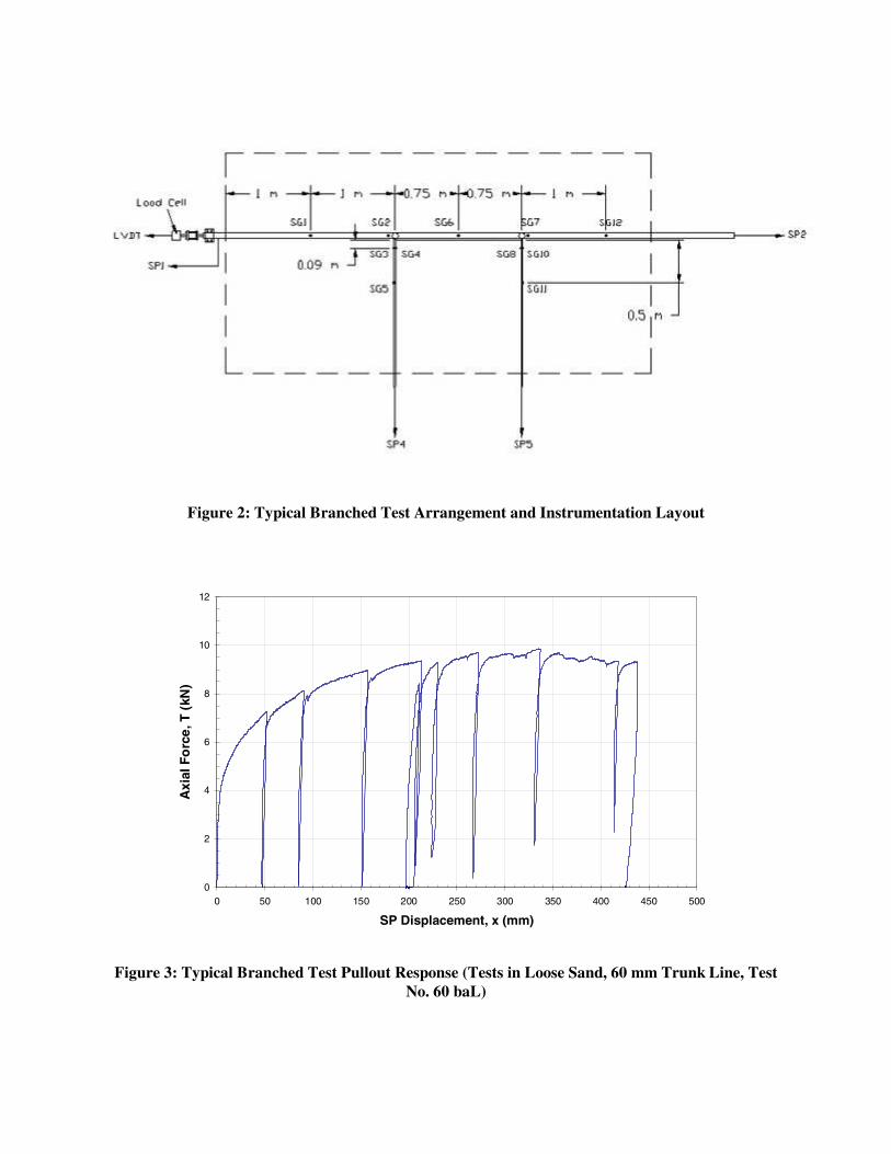
Figure 2: Typical Branched Test Arrangement and Instrumentation Layout
0
2
4
6
8
10
12
0 50 100 150 200 250 300 350 400 450 500
SP Displacement, x (mm)
Axi
al F
orc
e, T
(kN
)
Figure 3: Typical Branched Test Pullout Response (Tests in Loose Sand, 60 mm Trunk Line, Test No. 60 baL)

It was noted that a more adequate analysis and prediction can be made if the contributions to the pullout resistance from the branches are estimated, by isolating resistances from individual components. It was judged that the contribution from the 15 mm branches would be equivalent to the difference in pullout forces between the tests on branched specimens and those on the corresponding tests on straight specimens from Anderson [12]. Table 1 provides the contributions of the branches and trunk line to the pullout force that were estimated using this approach. It can be noted that the contribution from branched sections to the axial pullout force estimated from 115-mm diameter trunk line pullout tests are essentially identical to those estimated from 60-mm diameter trunk line tests. This not only indicates the suitability of the above approximation for the difference in pullout forces between branched and non-branched tests, but also suggests that the performance of the branch is not significantly affected by the size of the trunk line.
Table 1: Approximate contributions to peak pullout resistance by pipeline components (Tests on Loose Sand)
Test ID Branched
Tmax (kN)
Straight Tmax (kN)
Total Branch Contribution
(kN)
Branch Contribution
(kN)
115baL 8.7 2.8* 5.9 2.95
60baL 7.0 1.1* 5.9 2.95 *Note: These results from straight pipe tests, Anderson [12]. It was noted that the contribution to the observed axial resistance in the trunk line by the branches is governed by a pipe-soil response mechanism that involves a combination of both transverse axial pullout and transverse lateral movement behaviours of the branched pipes. Figure 4 presents the variations in the axial displacement of trunk line and branch ends measured using the string potentiometers for Test No. 115baL. As can be seen, the response of the axial displacement in the branches lags behind those for the trunk line during the test. This indicates that considerable bending and elongation of the pipe occurs during initial trunk line displacements, followed by axial movement of the branch. It can also be noted from the figure that the slope of the branch displacement curve does not reach parallel with the displacement curve of the trunk line, indicating that elongation of the branch pipe was continuing at the time of termination of the test. Figure 5 presents the measured strains at several locations along the 115 mm diameter trunk line for a typical test with 15 mm branched piping. Each curve represents the strain distribution (based on strain gauge measurements) for a given displacement of the trunk line leading end. Of particular interest is the strain gauge located just in front of the base of the first branch, located 2000 mm from the front edge of the test chamber. As can be seen in the figure, especially at trunk line displacements greater than about 20 mm, relatively high localized strains seem to develop in the in the trunk line just in front of the first branch. Beyond this point, the trunk pipe strains decrease to a relatively low level, indicating that the majority of the pullout resistance is generated by an anchoring effect caused by the first tee. The strain response behind the branch indicates that, while this relatively larger diameter trunk line is able to accommodate the increased pullout force resulting from the anchoring effect of the branch, it is also able to continue to transfer the loads along the trunk line. Figure 6 shows the photograph of a typical branch deformation following a pullout test for the relatively large diameter (115-mm diameter) trunk line; clearly, the large strains and potential vulnerability is apparent on the branched section. In tests on 60-mm diameter trunk lines, the anchoring effect caused by the branched pipe appeared to be significant to cause much higher localized strains on the trunk line at a point immediately in front of the branch (see Figure 7)

than those observed for larger pipes (see Figure 5). Essentially, there was no significant transfer of load along the trunk line past the first tee. This clearly showed that the presence of branched sections in smaller diameter trunk pipes could cause the trunk line to be more vulnerable to damage than the branch. (Note: This is in contrast to the large-diameter trunk pipes where the higher vulnerability was observed in the branched pipe).
0
100
200
300
400
500
0 50 100 150 200 250 300 350 400 450 500
SP1 Displacement, x (mm)
SP
Dis
pla
cem
ent
(mm
)
Trunk Line Leading End
Trunk Line Trailing End
Branch 1 Axial Displ.
Branch 2 Axial Displ.
Figure 4: Measured Displacements of Pipe Ends (115 mm Trunk Line, Test No. 115baL)
-10000
-8000
-6000
-4000
-2000
0
20000 1000 2000 3000 4000 5000
Distance Along Pipe (mm)
Str
ain
(m
icro
stra
in)
1 mm
2 mm
5 mm
10 mm
20 mm
50 mm
75 mm
100 mm
200 mm
SG ahead of Tee
SG behind Tee
Figure 5: Local Strain Readings along Trunk Line for 115-mm Diameter Trunk Line

Figure 6: Photograph of Deformed Specimen After Testing
-25000
-20000
-15000
-10000
-5000
0
50000 1000 2000 3000 4000 5000
Distance Along Pipe (mm)
Str
ain
(m
icro
stra
in)
1 mm
2 mm
5 mm
10 mm
20 mm
50 mm
75 mm
100 mm
200 mm
275 mm (max disp.)
Figure 7: Local Strain Readings along Trunk Line for 60-mm Diameter Trunk Line

MECHANISMS OF SOIL RESISTANCE ON POLYETHYLENE PIPELINES For soil displacements occurring longitudinally to the pipe axis of a straight section of pipe, the currently accepted analytical models employ a friction based peak axial pullout resistance per unit length of pipe, tu, which is reached at some specified displacement, typically 2.5 mm (0.1 inch). The frictional resistance acting at the interface between the soil and pipeline is generally based on some fraction, f, of the internal friction angle, φ, of the soil. Further, the normal forces acting at the interface are an average between the vertical and horizontal effective stresses. The standard equation for axial pullout can thus be written as in Equation 1:
φγπ fk
HDT utan
2
1 0
+= [1]
Observations during tests on polyethylene pipe specimens indicate that the commonly assumed constants f and k0 are subject to some variation depending on the extensibility of the pipeline material. Because of the flexibility of PE, there is a reduction of the diameter of the pipe due to pipe elongation. In addition, shear-induced volume changes takes place in the soil at the pipe-soil interface. As a result of these activities, arching of the soil outside the soil-pipe interface zone could occur, and this, in turn, could lead to reduced normal soil stresses acting against the pipe, resulting in decreased pullout resistance. In very dense soils, the volume change may result in an increase in interface stresses due to dilation of the soil as the dense soils attempt to expand. Due to the significant differences in extensibility between polyethylene and steel, the pullout resistance behaviour noted above would not likely be evident during testing of steel pipelines. It is also important to note that the accurate estimation of k0 in both laboratory testing and field applications deserves particular attention. As can be seen in Figure 8, the prediction of pullout resistance (as recommended in the ASCE guidelines) is very sensitive to the variation of k0. Values for lateral earth pressure in the range of 0.5 to 1.0 are commonly assumed for native or lightly compacted soils, however, additional consideration should be given to compaction-induced lateral stress conditions, considerations for which are provided by Filz [13]. In many instances, the conditions of the native soils beneath and to the sides of the trench will influence the effective lateral earth pressure upon compaction of the soils. It is reasonable to assume, however, that as-built values of lateral earth pressure greater than 1.0 would be relatively uncommon. In addition to the discrepancies noted between the magnitude of experimental and predicted peak pullout resistance, the shape of the pullout resistance with displacement response should also be noted. The predictions shown in Figure 8 are based on the assumption that peak axial pullout resistance occurs at 0.25 mm (0.1 in), and it is based on those recommended for steel pipelines. However, the experimental results on PE pipes (solid curve, Figure 8) show that the peak pullout force occurs at a much greater displacement than 0.25 mm. This is due to the manifestation of a progressive failure response that is derived due the flexibility of the pipe and the full-scale nature of the test, rather than a uniform strain response that would be expected in a rigid or in a smaller element test.

0.0
0.5
1.0
1.5
2.0
2.5
3.0
0.0 1.0 2.0 3.0 4.0 5.0
Normalized Displacement x/D
No
rmal
ized
Pu
llou
t R
esis
tan
ce T
/ γH
DL
k0 = 0.5
k0 = 2.0
k0 = 1.5
k0 = 1.0
Figure 8: Typical Test Result (Straight Section) Versus Predictions For soil displacements relative to pipeline configurations containing junctions, such as the branched junctions tested in this study, there exists no simple analytical model by which to evaluate pipe strains and deformations. There appear to have been few attempts to model behaviour similar to the very large flexural deformations and “flow” through the soil experienced by small diameter, flexible pipes. The experimental observations indicate that these branched pipings are subjected to complex interaction with the soil, beginning as a lateral movement and transitioning to a nearly exclusively axial pull out from the soil. Further, the tee-junction joining the branches to the trunk line impart a geometric anomaly attracting significant localized strains, numerical models for which also do not appear to have been attempted. For existing analytical models, and for future attempts to numerically model soil-pipeline interaction, adjustments may be required in order to incorporate interface behaviours resulting from the soil volume change and polyethylene pipe extension and subsequent diametric reduction. In particular, vertical and lateral soil forces acting on the pipe may require a reduction proportional to pipe strains and shear-induced soil volumetric changes. Current analytical and numerical models lack such capabilities.
DISCUSSION A full-scale testing facility has been developed at the University of British Columbia to investigate the performance of buried piping configurations subjected to ground deformations. The facility essentially comprises a 3 m x 5 m soil box, with the capacity to test pipeline segments with up to one meter displacement. A detailed research program involving full-scale physical modeling has been undertaken to study soil-pipeline interaction during permanent ground displacements affecting distribution networks of PE piping. While the work stems from potential concerns in natural gas distribution areas where slow, continual ground movements are anticipated, the observations from the experiments are judged to be equally applicable to other forms of ground deformations, including those induced by earthquake liquefaction. The results of the research presented herein provides several pertinent observations relating to the behaviour of polyethylene pipelines during ground displacements, the effects of typical distribution

branches on pipeline performance, and the applicability of existing analytical models and methods to polyethylene and to branched geometry. In particular, insight has been provided into the behaviour of branched buried pipeline sections subject to permanent ground displacements. The results indicate that the contributions from the branches to the pullout resistance of a trunk line can be approximated by the difference in pullout forces between the tests on branched specimens and those on the corresponding tests on straight specimens. The results also suggest that the performance of the branch is not significantly affected by the diameter of the trunk line. Simple analytical models are unavailable for increases in pullout resistance due to compound geometries such as the branched junctions tested in this study. The experimental observations indicate that these branched pipings are subjected to a complex interaction with soil, beginning as a lateral movement and transitioning to a nearly exclusively axial pull-out from the soil. It is observed that the presence of branched sections in smaller diameter trunk pipes could cause the trunk line to be more vulnerable to damage than the branch, in contrast to the large diameter trunk pipes where the higher vulnerability was observed in the branched pipe. The reduction of the diameter of the PE pipes due to pipe elongation combined with shear-induced volume changes of soil at the pipe-soil interface seems to affect the pipe response against axial loading. Arching of the soil outside the soil-pipe interface zone, arising as a result of these activities, appears to result in reduced normal soil stresses acting against the pipe, and, in turn, resulting in decreased pullout resistance. Peak pullout resistances observed in the full-scale PE piping configurations occurred at significantly larger displacements than those suggested by published guidelines developed on the performance of steel pipelines. This is likely due to the manifestation of progressive failure at the soil-pipe interface which appears to be a direct result of the soil arching around the pipeline specimen associated with pipe flexibility and shear-induced soil volume changes.
ACKNOWLEDGEMENTS The research program at the University of British Columbia has been sponsored by Terasen Gas Inc. (formerly BC Gas Utility Ltd.). The authors wish to thank Mr. Scott Jackson, Mr. John Wong, Mr. Harald Schremp, and Mr. Doug Smith of the University of British Columbia Department of Civil Engineering for their technical assistance in commissioning the testing apparatus.
REFERENCES 1. Trautmann, C.H., O’Rourke, T.D. “Behaviour of Pipe in Dry Sand Under Lateral and Uplift
Loading.” Geotechnical Engineering Report 83-7, Cornell University, Ithaca, New York, 1983. 2. Trautmann, C.H., O’Rourke, T.D. 1985, “Lateral Force-Displacement Response of Buried Pipe.”
Journal of Geotechnical Engineering, Vol. 111, No. 9, September 1985, 1985: 1077-1093. 3. Paulin, M.J., Phillips, R., Clark, J.I., Hurley, S., Trigg, A. “Establishment of a full-scale pipline/soil
interaction test facility and results from lateral and axial investigations in sand.” Vol. V, 16th International Conference Offshore Mechanics and Arctic Engineering ’97, Yokohama, 1997: 139-146.
4. ASCE. “Seismic Design Guidelines for Oil and Gas Pipeline Systems.” ASCE Committee on Gas
and Liquid Fuel Lifelines. ASCE, New York, 1984.
5. ALA. “Guidelines for the Design of Buried Steel Pipe.” American Lifelines Alliance, 2001. 6. Cappelletto, A., Tagliaferri, R., Giurlani, G., Andrei, G., Furlani, G., Scarpelli, G. “Field Full Scale
Tests on Longitudinal Pipeline-Soil Interaction.” Proceedings, International Pipeline Conf., Calgary, Canada, ASME, 1998: 771-778,
7. Honegger, D.G. Personal Communication, 2004. 8. Petroff, L.J. “Review of the Relationship Between Internal Shear Resistance and Arching in Plastic
Pipe Installations.” Symposium on Buried Plastic Pipe Technology, ASTM STP 1093, George S. Buczala and Michael J. Cassady, Eds., ASME, Philadelphia, 1990: 266-280.
9. Bughi, S., Aleotti, P., Bruschi, R., Andrei, G., Milani, G., Scarpelli, G., Sakellariadi, E. “Slow
Movements of Slopes Interfering with Pipelines: Modelling and Monitoring.” Proceedings of the 15th International Conference on Offshore Mechanics and Arctic Engineering, ASME, 1996: 363-372.
10. Bruschi, R., Glavina, S., Spinazze, M., Tomassini, D., Bonanni, S., Cuscuna, S. “Pipelines
Subjected to Slow Landslides Movements: Structural Modelling vs. Field Measurement.” Proceedings of the 15th International Conference on Offshore Mechanics and Arctic Engineering, ASME, 1996: 343-354.
11. Anderson, C., Wijewickreme, D., Mitchell, A. “Development of a Full-Scale Laboratory Testing
Facility for Soil-Pipeline Interaction Research.” Proceedings of the 56th Canadian Geotechnical Conference, Canadian Geotechnical Society, 2003.
12. Anderson, C. “Soil-Pipeline Interaction of Polyethylene Natural Gas Pipelines in Sand.” University
of British Columbia, Thesis, to be published, 2004. 13. Filz, G.M., and Duncan, J.M. “Earth Pressures Due to Compaction: Comparison of Theory with
Laboratory and Field Behaviour.” Transportation Research Record 1526, Transportation Research Board, Washington, D.C., 1996: 28-37.


![Web Interaction Scale[12]](https://img.pdfslide.us/doc/110x75/577cc07f1a28aba71190529f/web-interaction-scale12.jpg)