Embed Size (px)
Citation preview
MoDOT
TE 228 .F86 1988
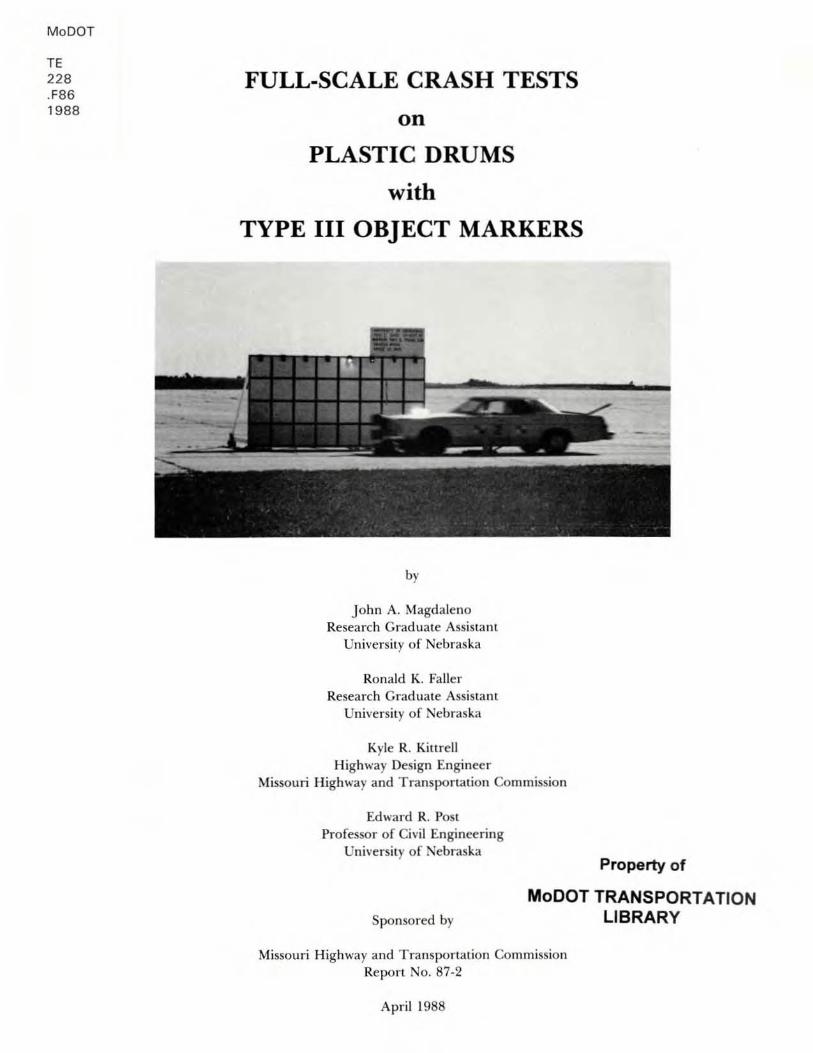
FULL-SCALE CRASH TESTS
on
PLASTIC DRUMS
with
TYPE III OBJECT MARKERS
by
John A. Magdaleno Resea rch Graduate Assistant
Un iversity of Nebraska
Ronald K. Faller Research Graduate Assistant
Un iversity or Nebraska
Kyle R. Kimel! Highway Design Engineer
Missouri Highway and T ransportation Commission
Edward R. Post Proressor or Civil Engineering
Un iversity or Nebraska Property of
Sponsored by
MoDOT TRANSPORTATION LIBRARY
Missou ri Highway and Transportation Com mission Report No. 87·2
April 1988
DISCLAIMER
This document is disseminated in the interest of informati on
exchange. The opinions, findings , and c o nclusions expressed i n
this publication are not necessarily those of the Departmen t of
Transpor tation. Federal Highway Administration. This report does
not constitute a standard , specifi c ati o n , or regulation .
The United States Go vernmen t does not endorse products or
manufacturers . Trade or rnanufact.urers names appear herein only
because they are considered essentia l t o the object of this
document .
ABSTRACT
The Missouri Highway and Transportation Department is
proposing the use of a two -piece breakaway channelizer for
delineating traffic. This configuration consists of a Plasti c
Drum with a Type III Object Marker mounted on top of it using two
polycarbonate plastic connectors between the drum and the object
marker. The reason for using this type of channel i zer stemmed
from many anticipated benefits such as: F irst . plas t ic
connectors pose a lesser threat to traffic than metal connectors
if detachment should occur. Second , since the object markers are
above the splash zone, they stay cleaner during extreme weathe r
conditions. Third , the object markers are less expensive than
warning lights and, with the exception of clean ing , no
maintenance is required after installation. To determine whether
or not the configuration was satisfactory f or implementation , two
full-scale crash tests were conducted in accordance with the
"Recommended Procedures for th e Safety Performance Evalua tion o f
Highway Appurtenances," from the Na tional Coopera t i ve Highwa y
Research Program Report 230, Trans portation Research Board;
Mar ch, 1981.
Results of both tests showed that all of the required
performance criteria had been met; therefore , the Plastic Drum
with a Type III Object Marker was considered satisfactory .
TABLE OF CONTENTS
Page
I Acknowledgements i
n List of Tables ii
III List of Figures iii
IV Introduction 1
V Full-Scale Crash Test Details 2
l. Test Fa c il ity 2
2 . Test Article 6
3. Test Vehicles 9
4. Data Acquisiti on 14
5 . Performance Standards 21
VI Test Results 23
l. Test No. 1 25
2 . Tes t No . 2 34
VII Conclusions 42
VIII Tes t Ar ticle Recommenda tions 44
IX References 45
ACKNOWLEDGEMENTS
The authors wish to express their appreciation and thanks to
the f ollowing people who made a contribution to the success of
this research project .
Federal Highway Administration
Donald F. James
Safety Programs Engineer
Missouri Division
Estrada Incorporated
Designer of polycarbonate connectors
University of Nebraska
Michael Cacak (Manager - Automobile Support Services)
Patrick Barrett (Assistant Manager - Aut omobi le Support Services )
James Dunlap (Manager - Photographic Product ions)
Vince Ullman (Photographic Technician)
Gerald Fritz (E.E. Technician)
Torn Grady (E.E. Technician)
William Kelly (Professor and C.E. Chairman)
EUQene Matson (C.E. Research Technician)
Brian Pfeifer (M.E. Student)
Terry Brown (C . E. Student)
Mary Lou Tomka (e.E. Administrative Assistant)
Mary Lou Wegener (C .E. Secretary - Typis t)
Marilyn Mues (C.E . Secretary - Typist)
i
LIST OF
1. Summary of Test Results
2 . Summary of Results . Test No .
3. Time-Event Summary for Test
4. Summary of Results , Test No .
5 . Time-Event Summary for Test
TABLES
1
No. 1
2
No. 2
ii
Page
24
27
29
35
37
I
I
I I I I I I
I 1 I
I
I
LIST OF FIGURES
Page
1. Test Site Faci lity . 3
2. Sketch of Cable Tow System 4
3. Cable Guidance System and Tow Vehicle 5
4. Schematic of Plastic Drum with Type III Object Harker 7
5. Photos of Plastic Drum with Type III Object Marker 8
6. Test Vehicle No.1 10
7. Test Vehicle No.1 Dimensions
8. Test Vehicle No.2
9. Test Vehicle No.2 Dimensions
10. Photos o f Mounted Accelerometers
11. Flowchart of Metraplex Data Acquisition System
12. Photos of Data Acquisition System
13. High-Speed Cameras.
14 . Schematic of Camera Layout
15. Sequential Photos, Test No. 1
16. Change in Velocity, Test No.1
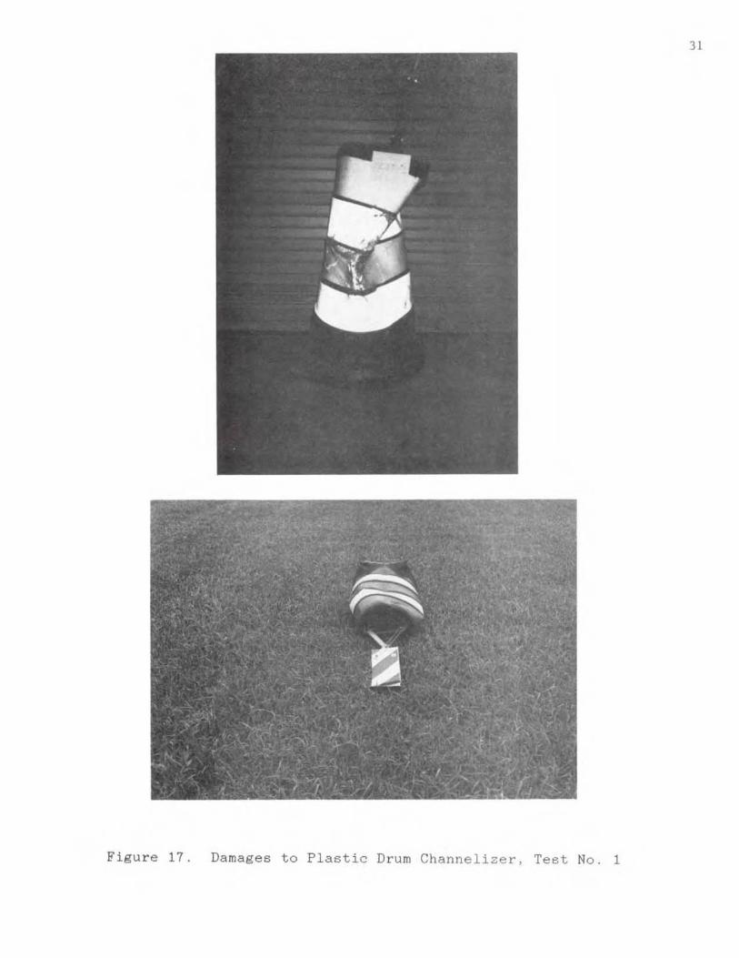
17. Damages to Plastic Drum Channelizer . Tes t No.1
18. Polycarbonate Connectors After Test No. 1
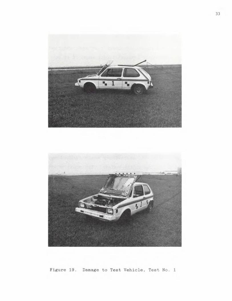
19. Damage t o Test Vehicle. Test No.1
20. Sequential Photos, Test No .2
21 Change in Velocity, Test No.2
22. Damages to Plastic Drum Channelizer , Test No.2
23. Polycarbonate Connectors After Test No .2
24. Damage to Test Vehicle Test No.2
iii
•
•
11
12
13
16
17
18
19
20
28
30
31
32
33
36
38
39
4 0
41
INTRODUCTION
For safety purposes, federal requirements have made it
mandatory that all roadside signs and luminaires located within a
designated clear zone be designed to breakaway under impact .
Therefore, the Missouri Highway and Transportation Department is
proposing the use of Plastic Drums with Type III Object Markers.
This system is considered a t.wo-piece breakaway channeli2er and
uses two polycarbonate plastic connectors to attach the object
marker to the drum . Since this system has never been tested to
determine what happens to the device after impact, the foll owing
objectives were established. First is the effect. that impact has
on the operation of t -he vehicle. Second is the effect. that
impact has on the safety of the vehicle occupants . Third is the
amount of damage done to the channelizer and vehicle .
The major concern of this project was to see if the object.
marker would remain attached to the drum. If it detached , the
next concern was whether or n ot it would penetrate. or show
potential to penetrate, the passenger compartment of the vehicle
or present undue hazard to other traffic. In order to certify
the effectiveness of the p olycarbonate connectors in keeping the
object marker attached to the drum , testing procedures were
conducted i n accordance with the criteria given by the National
Cooperative Hiqhway Research Program Report 230 (NCHRP 230) OJ.
and the American Association of State Highway and Transportation
Officials (AASHTO) (~.l, specifications.
FULL-SCALE CRASH TEST DETAILS
TEST FACILITY
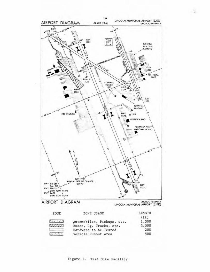
The test. si t.e faci lity was located at Lincoln Air-Park on
the northwest corner of the west apron of the Lincoln Mun i cipa l
Airport. The test facility, shown in Figure I, is approximately
7 miles n orthwest of the University of Nebraska-Linco ln .
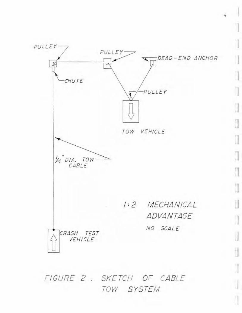
A reverse cable tow system. with a 1:2 mechanical advantage ,
was used to propel the test vehicle. Thus , the distance traveled
and the speed of the test vehicle wer e twi ce that o f the tow
vehicle. Th e test vehicle was released fr om the t ow cable
approxi ma tely 6 feet. before impact with the plastic drum. A
sketch of the tow system is shown in Figure 2 and a photograph of
the tow vehicle is s hown in Figure 3.
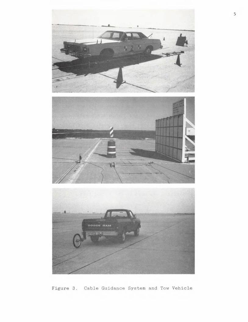
The cable guidance system , developed by Hinch (~), was used
to guide the test vehicle as shown in Figure 3. A guide-flag ,
which attached the front-left wheel of the test vehicle to the
quide cable. was sheared off approximately 6 feet before impact
with the plastic drum. The 3/8 in. diameter guide cable was
tensioned to 3,000 lbs. and was supported latera lly and
vertically every 50 feet by hinged stanchions. The stanchions
were knocked down by the guide-flaq as the vehicle passed. The
cable guidance system was approximately 1 , 000 feet for the first
test when the 1 . 800 lb. test vehicle was used , and approximately
1.500 feet for the second test when the 4 , 500 lb . test vehicle
was used.
2
I I ]
1 )
J
J
1
I I
AIRPORT DIAGRAM ".
,f,l·232 (FAA) LINCOlN M UNICIPAL AIRPORT (LNK)
UNCOlN. N!UMU,
~ • • --
• ~~ *Ilil
~ ,.NUbSO.~NG ~""~r-\ . NfUASItA ... ~ .... y ~ . I1OHAl GU",~O
•
AIRPORT DIAGRAM UNeOOl. NEWSU LINCOlN MUNICIPAL AIRPORT (LNK)
ZONE
VII 1711 ~:§
1 I I:'.· . ,', -. I e - : I
ZONE USAGE
~utomobiles . Pickups , etc . Buses . Lg. Trucks. etc . Hard~are to be Tested Vehicle Runout Area
Figure 1. Test Site Facility
LENGTH (f t ) 1, 300 3, 000
200 500
3
4
PULLEY7 I P~? DEAD - END ANCHOR I X
~CHU TE 1
fJ -PULLEY I
0 I ]
TO'!I VEHICLE
I ';/ DIA. TOW 1
CABLE
1
I I: 2 MECHANICAL I
AD VA NTAGE I NO SCAL E
if CRASH TEST I VEHICLE
I I
FIGURE 2 . SKETCH O,~ CABLE
TOVI' SYSTEM
5
Figure 3. Cable Guidance System and Tow Vehicle
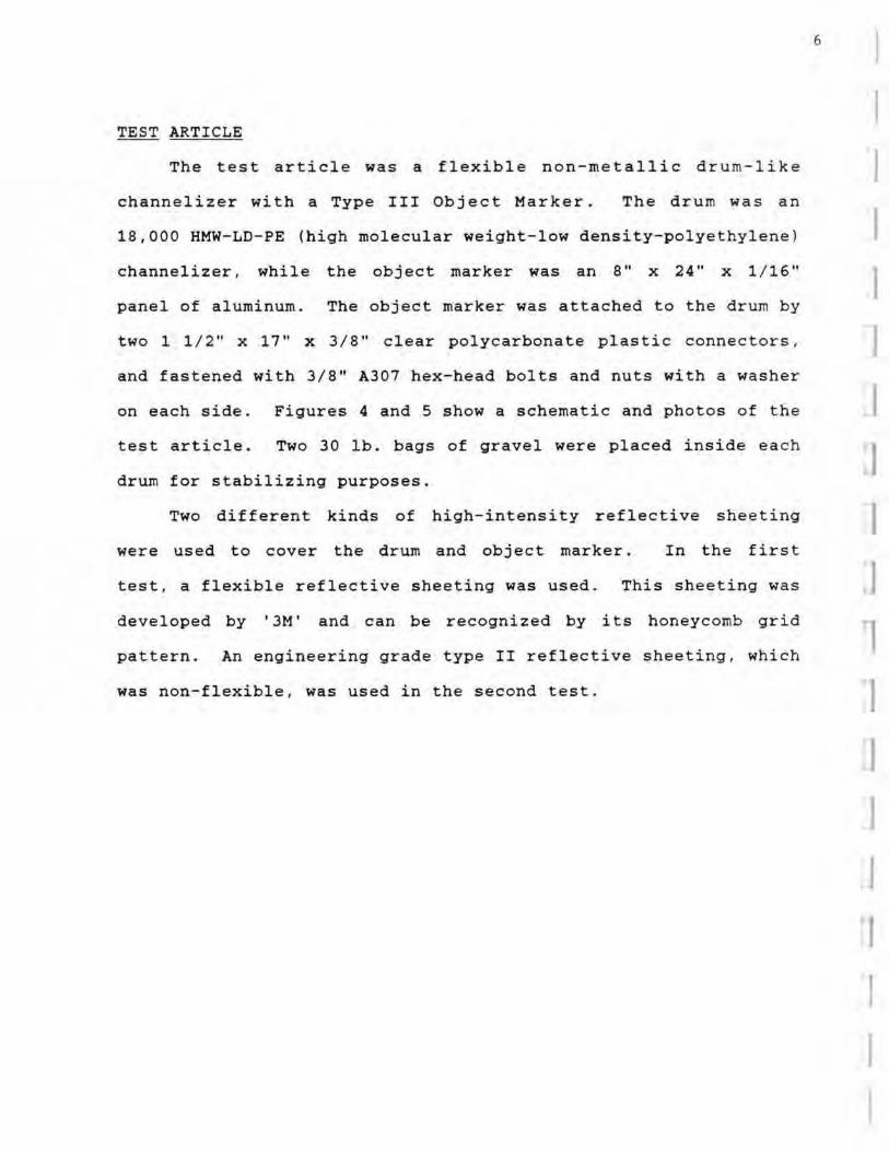
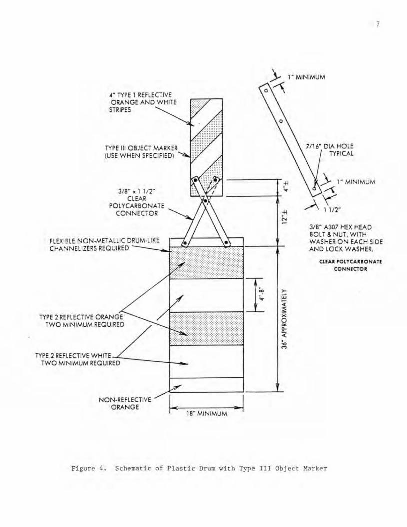
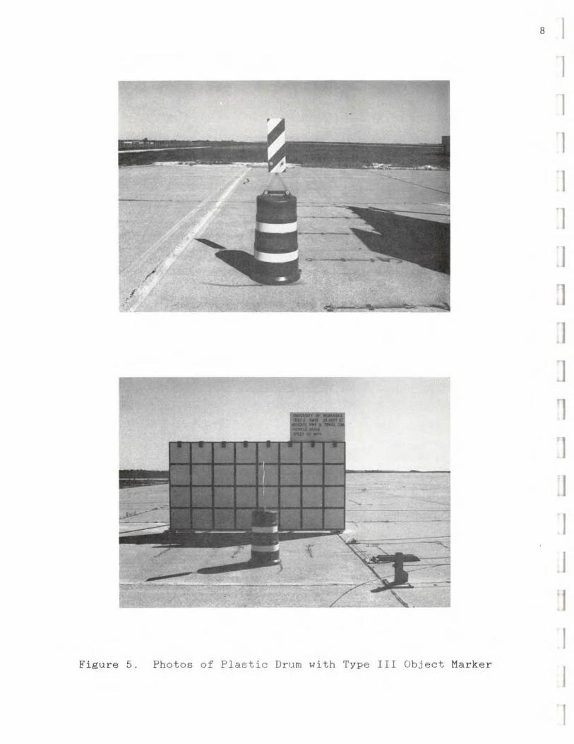
TEST ARTICLE
The test article was a flexible non-metallic dru m-like
channelizer with a Type III Object Marker. The drum was an
18,000 HMW-LD- PE (high molecular weight-low density-polyethylene )
channelizer, while the object marker was an 8" x 24" x 1 / 16"
panel of aluminum. The object marker was attached to the drum by
two 1 1 / 2" x 17" x 3 / 8" clear polycarbonate plastic c onnectors ,
and fastened with 3 / 8" A307 hex-head bolts and nuts with a washer
on each side. Figures 4 and 5 show a schematic and photo s of the
test article. Two 30 lb. bags of gravel were placed inside ea c h
drum for stabilizing purposes.
Two different kinds of high-intensity reflective sheeting
were used to cover the drum and object marker. In the first
test , a flexible reflective sheeting was used . This sheeting was
developed by '3M' and can be recognized by its honeycomb grid
pattern. An engineering grade type II reflective sheeting , wh i c h
was non-flexible, was used in the second test .
6
I I I 1 I I I I 1 I I I I I I I
.. ~ TYPE 1 REFLECTIVE ORANGE AND WHITE
STRIPES
TYPE III OBJECT MARK E,R (USE WHEN SPECIFIED)
J/B ~ ;I. I 112~ CLEAR
POlYCARBONATE CONNECTOR
FL EXISLE NON·MET ALLIC D~RU::M.::..:. L::.' K:.::E ..... h~b;2G CHANNELIZERS REQUIRED
TYPE 2 REFLECTIVE ORANGE TWO M INIMUM REQUIRED
TYPE 2 REflECTIVE WH I TE~:""' ____ +-.,,_ TWO MINIMUM REQUIRED
NON·REfLECTIVE ORANGE I.. 18" MINIMUM ;0 I
.. ,.
7
~ '-MINIMUM
0:--\
7116- OIA HOLE TYPICAL
... > '-MIN IMUM • ~ ~
... .A ~" • N
3/ 8" A307 HEX HEAD BOLT&. NUT, WITH WASHER ON EACH SIDE AN D l O CK WASHER.
elf .... 'Ol YCA ... ONATI C:ONNICTOII;
,.. -w -~ x 0 ~ ~ ~
< • ~ M
Figure 4 . Schematic of Plastic Drum with Type III Obj ect Marker
Figu re 5. Photos of Plastic Drum with Type III Object Ma rker
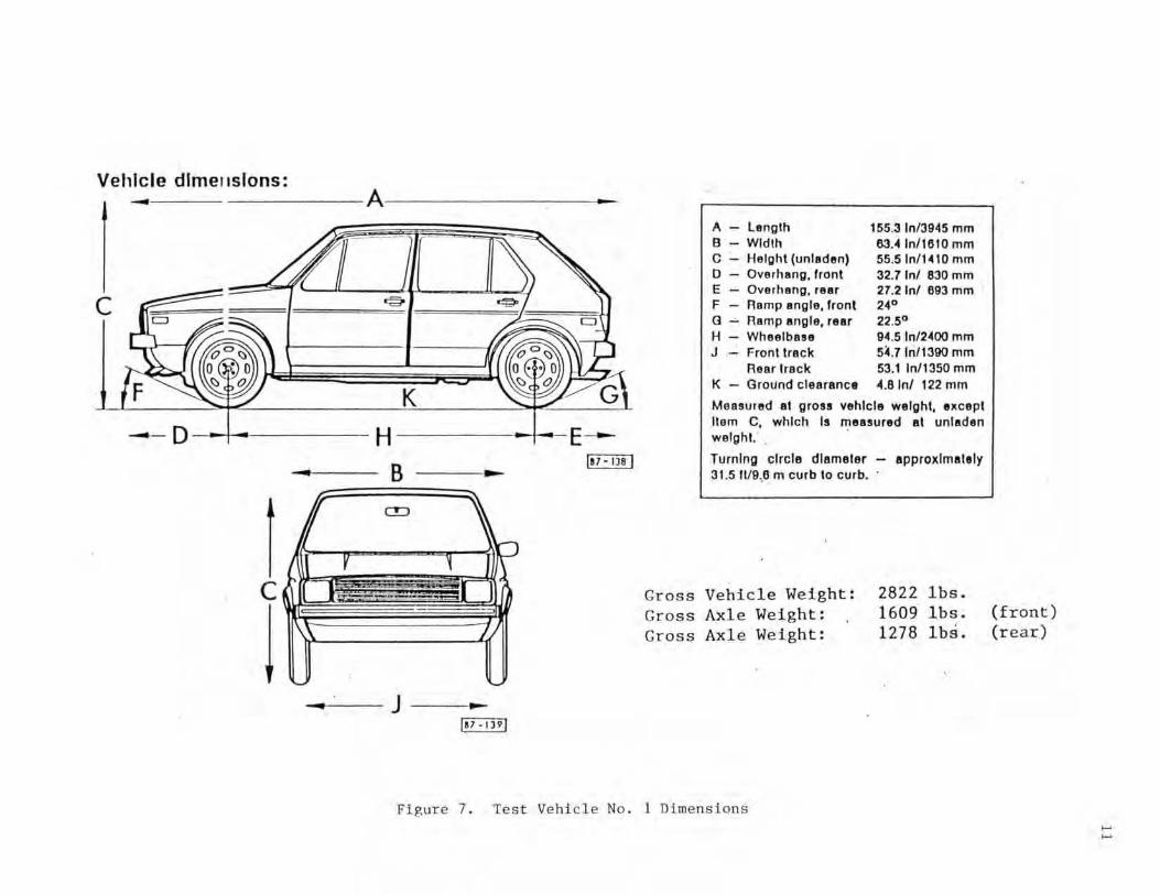
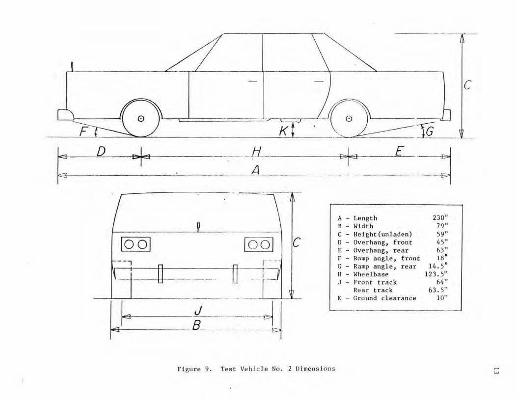
TEST VEHICLES
Two different test vehicles were used in the testing. A
1979 Volkswagon Rabbit. weighing approximately 1.840 Ibs. , was
used in the first test and a 1978 Mercury Grand Marquis ,
weighing approximately 4.590 Ibs., was used in the seco nd test.
Pictures of the test vehicles are shown in Figures 6 and 8, with
vehicle dimensions shown in Figures 7 and 9.
The front wheels of both vehicles were aligned to a t oe- in
value of zero-zero so that the vehicle would track properly along
the guide-cable.
Two 8 in. square , black and white targets were placed 4 2
inches apart (on center) on the test vehicles to aid with the
analysis of the high-speed film. In addition to the targets, two
58 flash-bulbs were mounted on the bood of b oth vehicles to
record the time of impact with the drum on the high-speed fil m.
The flash-bulbs were fired by a pressure switch which wa s taped
to the front of the bumper.
9
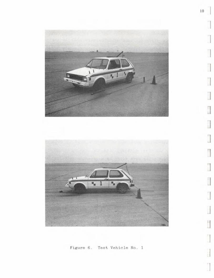
Figure 6. Test Vehicle No. 1
10 I
I I I I I I J I ']
1 rl
.I I
.1 'J I I I
VehIc le dlmellslons: -------A------~--
c
- - D- -t------H ----t--E~ I,,-ml
t c
! --~- J
A - length 155.3 ln/3945 mm 8 - Wldt" 63.4In/ 1610 mm C HeIght (unladen) 55.510/ 10410 mm 0 Overhang, fronl 32.7 Inl 830 mm E Oyer hang, reer 21.2101 693 mm F Ramp angle. Iront ,." 0 ~ Ramp angle, rear 22.5° H Wheelb858 94 .510/2400 mm J - Fronllrack 5~ . 7 In11390 mm
Rear track 53.11n/1350 mm K - Ground clearance 4.81nl 122 mm
Measured at gron vehicle weight, fll! cepl lIem C, which Is measured al unladen weigh!. . .
Turning clrcla diameter 31.511/9,6 m c\lIb to curb.
Gr oss Vehic l e Weight: Gross Axle We ight: Gross Axle Weight:
approKlmal.Iv
2822 lb •. 1609 lb •. 1278 lb'; .
Figure 7 . Test Veh icle No. I Dimensions
(front) (rear)
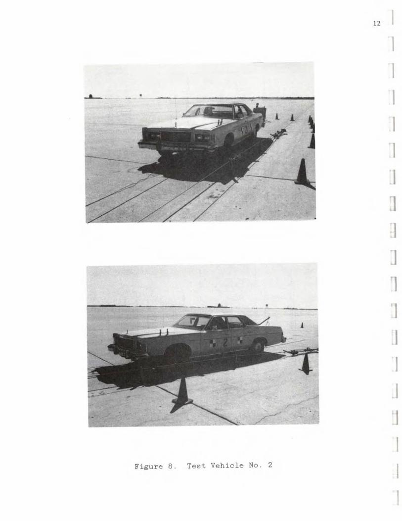
Figur e 8. Test Vehicle No.2
12 I 1
I
c
01==== --- ..
F K
~ D eol~ -.tL E3r E
~ A
- . - -- . . .
A - Length 230"
~ B - Width 79" ----
10 01 1001 c --1 r - -
,.1 _._-_ .. .
C - He Jght(unladen) 59" D - Overhang , fron t 45" E - Overhang, rear 63" F - Ramp angle, front IS· C - Ramp angle, rear 14. 5-H - Wheelbase 123 . 5" J - Front track 64 "
Rear trac k 63 . 5" ._------ -
~ ~- ~.--~--- :1j K - Ground c l earance 10"
Figure 9. Test Veh 'lcle No.2 Dimensions
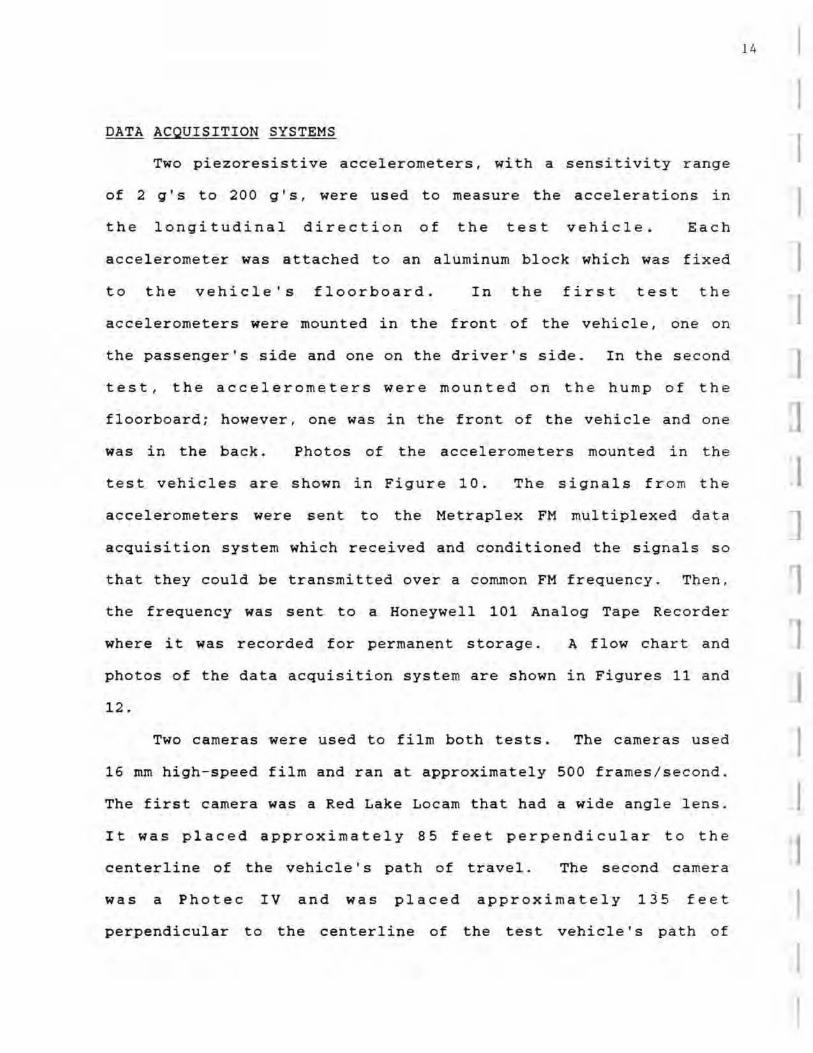
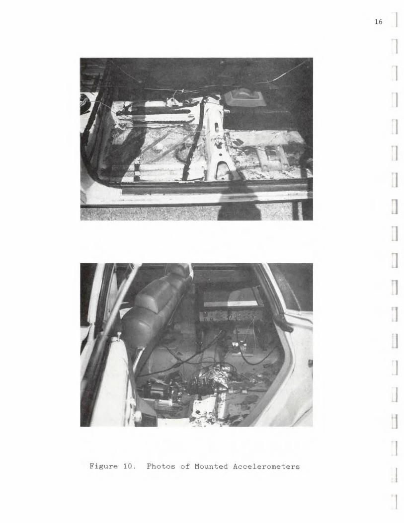
DATA ACQUISITION SYSTEMS
Two piezoresistive accelerometers, with a sensitivity range
of 2 g'5 to 200 glS. were used to measure the accelerat ions in
the longitudinal direction of the test vehicle. Each
accelerometer was attached to an aluminum block which
to the vehicle's floorboard. In the first
was
test
fix e d
th e
accelerometers were mounted in the front of the vehicle, one on
the passenger's side and one on the driver's side. In the seco nd
test . the ac celerometers were mounted on the hump of the
floorboard; however . one was in the front of the vehicle and one
was in the back. Photos of the acceleromete rs mounted in the
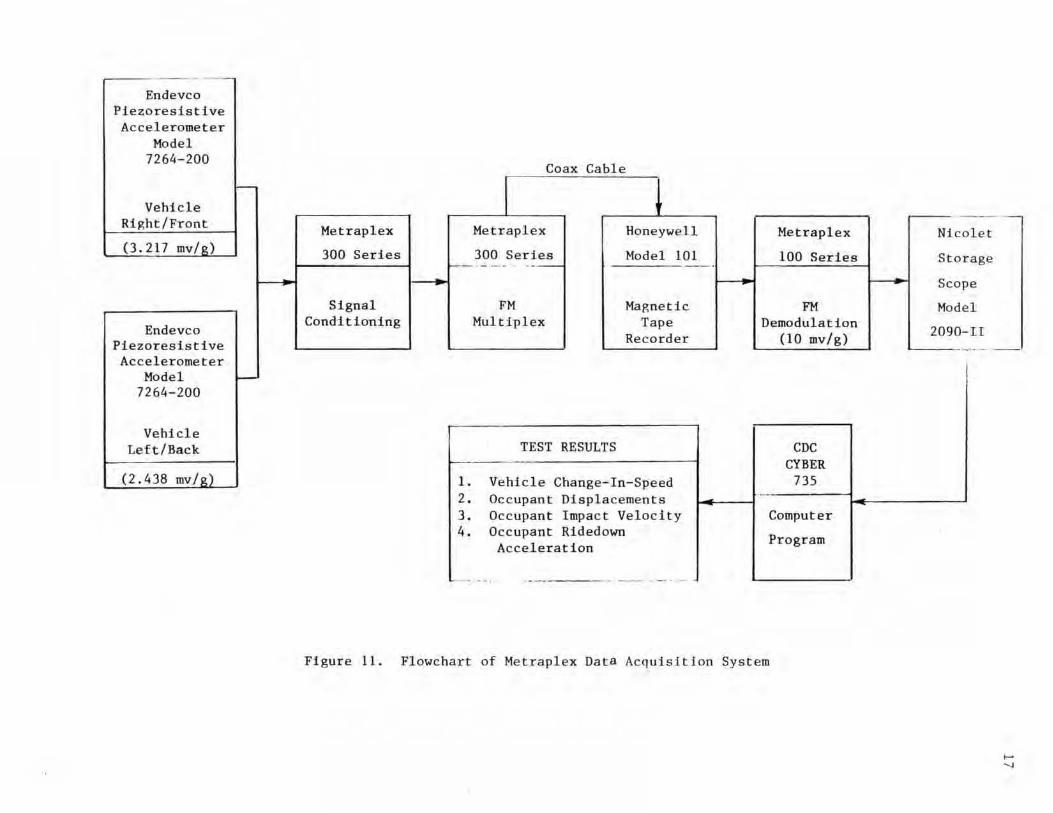
test vehicles are shown in Figure 10. The signals fr om the
accel erometers were sent to the Metraplex FM mul tiplexed data
acquisition system which received and condit i oned the signals s o
that they could be transmi tt ed over a common FM frequency. Then.
the frequency was sent to a Honeywell 101 Analog Tape Recorder
wher e it was recorded for permanent storage. A flow chart and
photos of the data acquisition system are shown in Figures 11 and
12 .
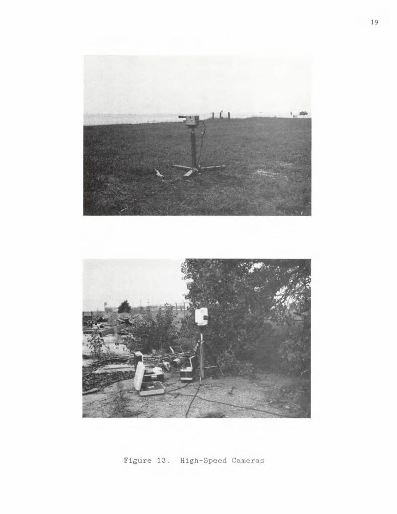
Two cameras were used to film both tests . The cameras used
16 mm high-speed film and ran a t approximately 500 frames / second .
The first camera was a Red Lake Locam that had a wide angle lens .
It was placed approximately 85 feet perpendicular to the
centerline of the vehicle's path of travel. Th e second camera
was a Phote c IV and was placed approximately 135 feet
perpendicular to the centerline of the test vehicle's path of
14
I I I 1
I ]
I I I
I I
I
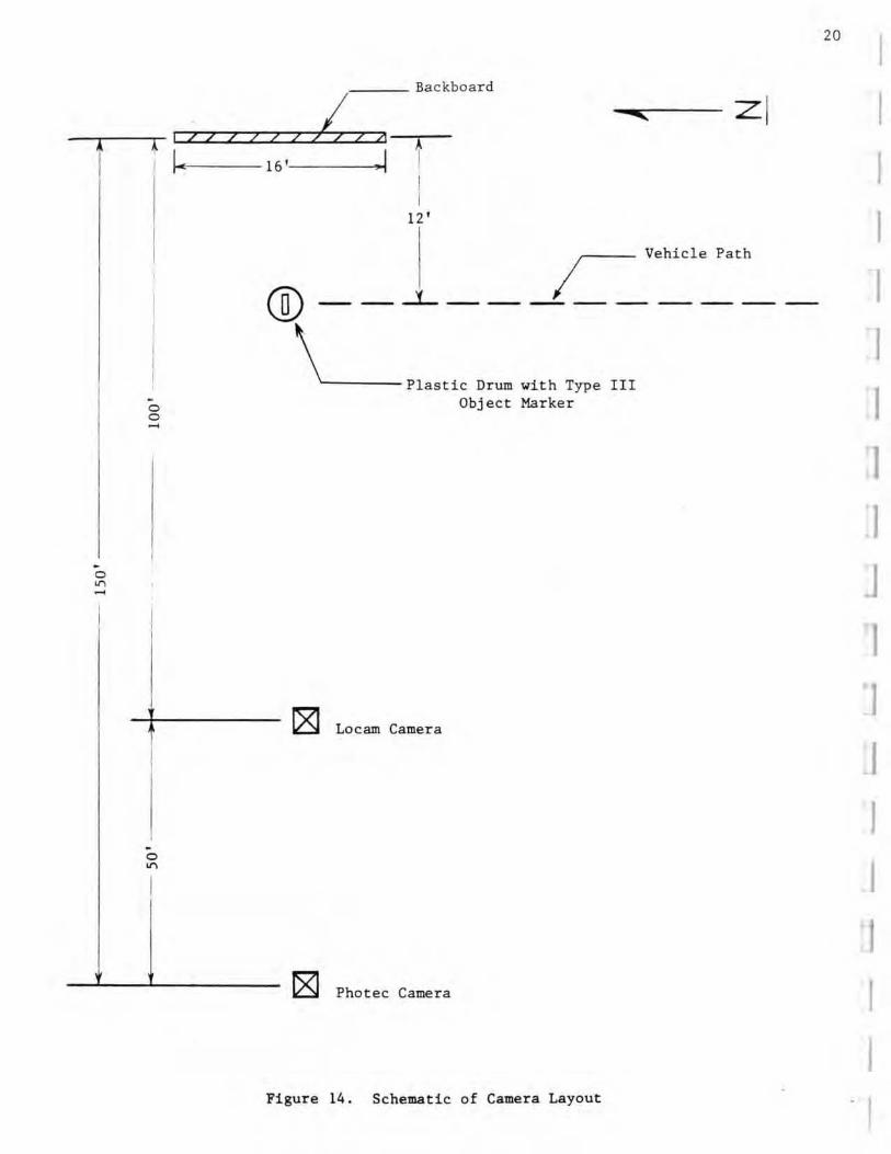
travel. Figure 13 shows photos of both cameras and Figure 14
shows a schematic of the camera layout.
An 8 ft. hiOh by 16 ft. long backboard, with a 2 ft. line
grid layout . was used as a reference f o r the analysis of the
high-speed film. The backboard was placed facing the cameras 12
feet from the centerline of the vehicle's path of travel . The
camera divergence correction factors were also taken into
consideration in the analysis of the high-speed film .
Eight pressure switches , spaced at 5 ft. intervals . were
used to determine the speed o f the vehic le before and af te r
impact. Four switches were placed in fr ont of the channelizer
and four switches were placed in back o f the channelizer along
the vehicle's path. Ea ch switch wou ld fire a SB flash-bulb ,
which was mounted on the backboard, as the r i ght front tire of
the vehicle rode over it. Then , since the distance between
pressure switches was known , by counting the number of frames
from the high-speed film between flashes and calibrating the
camera speed in frames per second , one could determine the speed
of the test vehicle as it passed over a particular pressure
switch.
A VanGuard Motion Analyzer 'Was used to analyze the high
speed film frame by frame.
15
16
Figure 10. Photos o f Mounted Accele r ometers
I
I 'I J
J 'J J
'1 J
1
I I 1
-- --Endevco
Plezoresist i ve Acceleromet er
Model 7260-200
I-Vehicle
Right/Front
(l.2 17 mv/o)
Endeveo Piezoresistive Accelerometer
Model I-7264-200
Vehicle Lef t / Hack
(2.438 mviR)
Me traplex
300 Series
Signal Conditioning
Coax Cabl e
Metraplex Honeywell
300 Seri es Model 101 ~ - ... .. - - _.
FM Magnetic Multiplex Tape
Recorder
TEST RESULTS
I. Vehicle Change-In-Speed 2 . Occupant Displaceme nt s 3 . Occupant Impact Velocity 4. Occupan t Ridedown
Acce l e rat i on
Hetrap l ex
100 Series
FM Demodulation
(10 my/g)
CDC CYBER
7JS _. Comput er
Program
Fi gure 11. Flowchart of Metrapl ex Data Acquisit i on System
Nl e alet
St o rage
Seo pe
el
O-II
Mod
209
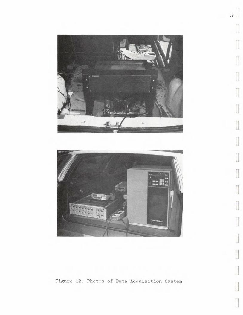
Figure 12. Photos of Data Acquisition System
[8 I I I I I I I J I J 1 'J
J
I I I
19
Figure 13. High -Speed Cameras
. o ~ -
. o o
. o ~
I II I I
I.-
Backboard
lin z l " I I 4 t 16 • .1
I I
12 •
@-~ Vehicle Path
_...:1-. ________ _
L Plastic Drum with Type Obj ect Marker
~ Locam Camera
~ Photec Camera
Figure 14. Schematic of Camera Layout
III
2D
I I I I J
I J I I I I I J
I I
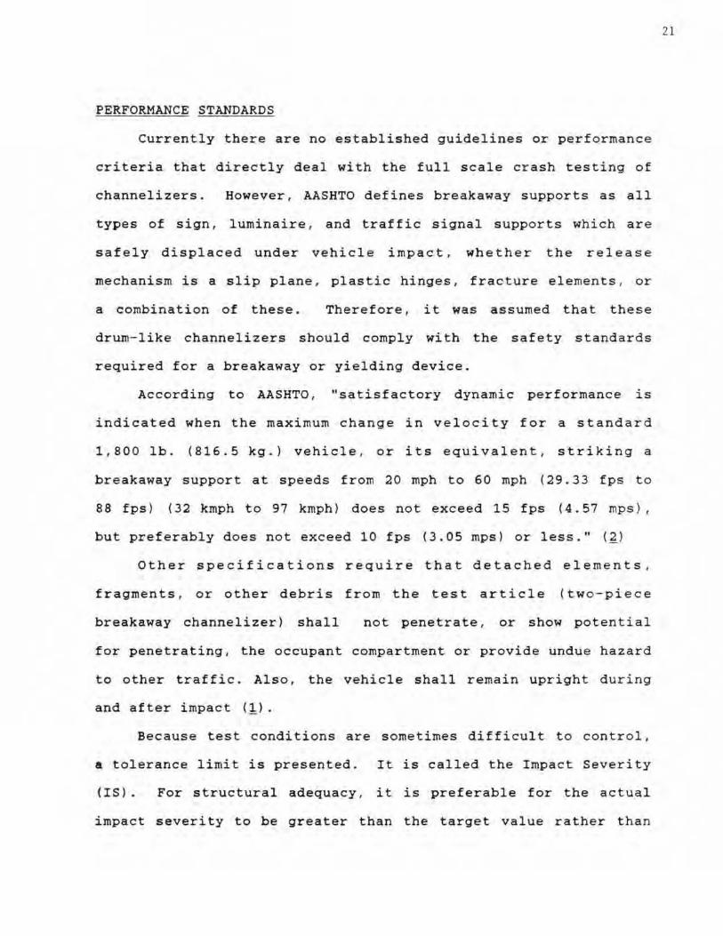
PERFORMANCE STANDARDS
Currently there are no established guidelines or performance
criteria that directly deal with the full scale crash testing of
channelizers. However , AASHTO defines breakaway supports as all
types of sign , luminaire , and traffic signal supports which are
safely displaced under vehicle impact , whether the releas e
mechanism is a slip plane . plastic hinges, fracture elements , or
a combination of these . Therefore , it was assumed that these
drum- like channelizers should comply with the safety standards
required for a breakaway or yielding device.
According to AASHTO , "satisfactory dynamic performance is
indicated when the maximum change in velocity for a standard
1,80 0 lb. (8 16.5 kg .) vehicle, or its equivalent , striking a
breakaway support at speeds from 20 mph to 60 mph (2 9.33 fps to
88 fps ) (32 kmph to 97 kmph ) does not exceed 15 fps (4.57 mps ) ,
but preferably does not exceed 10 fps (3 . 05 mps) or less." (~)
Other specifications require that detached elem ent s .
fragments , or other debris fr om the test article (t.wo-piece
breakaway channelizer) shall not penetra te, or show poten ti al
for penetrating, the occupant compartment or provide undue hazard
to other traffic. Also, the vehicle shall remain upright dur i ng
and after impact (1).
Because test conditions are sometimes diffi c ult to contro l .
s tolerance limit is presented. It is called the Impact Severity
(IS) . For structural adequacy , it is preferable for the actual
impact severity to be greater than the target value rather than
21
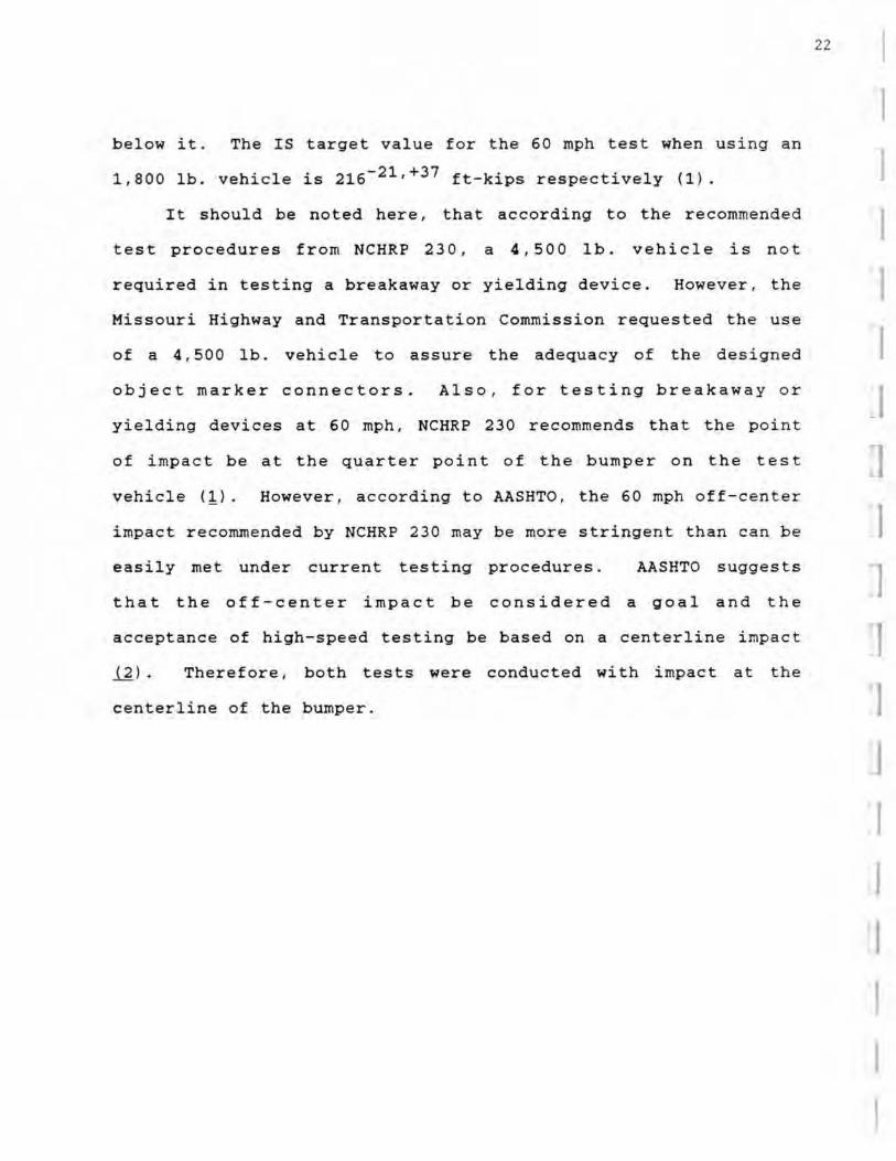
below it. The IS target value f o r the 60 mph test when using an
1.800 lb. vehicle is 216- 21 .+37 ft-kips respectively (1).
It should be noted here . tha t according to the recommended
test procedures from NCHRP 230 . a 4,500 lb. vehicle is not
required in testing a breakaway or yielding device. However , the
Missouri Highway and Transportation Commission requested the use
of a 4.500 lb. vehicle to assure the adequacy of the designed
object marker connectors . Als o, for testing breakaway o r
yielding devices at 60 mph, NCHRP 230 recommends that the point
of i mpact be at the quarter point of the bumper on the test
vehicle (1). However. a ccording to AASHTO , the 60 mph off-center
impact recommended by NCHRP 230 may be more stringent than can be
easily met under current testing procedures. AASHTO suggests
that the off-center impact be considered a goal and the
acceptance of high-speed testing be based on a centerline impact
ill . Therefore , both tests were conducted with impact at the
centerline of the bumper .
22 I 1
I I I I I 1 I I I I J
I
I I
TEST RESULTS
The individual results of both full-scale crash tests are
included in the following section; a summary of the results is
given in Table 1.
Though accelerometers were used in the testing, they were
not applicable in the tests analysis. The reason for this was
because the 'g' force produced by the impact was not large enough
to be recorded by the lower sensitivity range of the
accelerometers (2 g's). Therefore, the impact speed and the
change in velocity were obtained by analyzing the high-speed
film.
Because the 'g' force was less than 20 ' S in both tests, the
occupant displacement was negligible. Hence, the results of the
tests were compared to vehicle braking. This was done to compare
the change in velocity experienced by an occupant in the test
vehicle, to the change in velocity experienced by an occupant in
a vehicle if the brakes were applied and skidding occurred. In
figuring the change in velocity due to braking , the coefficient
of friction between the tires and the concrete pavement was taken
as 0.63 as recommended by the National Research Council, Highway
Research Board (!).
23
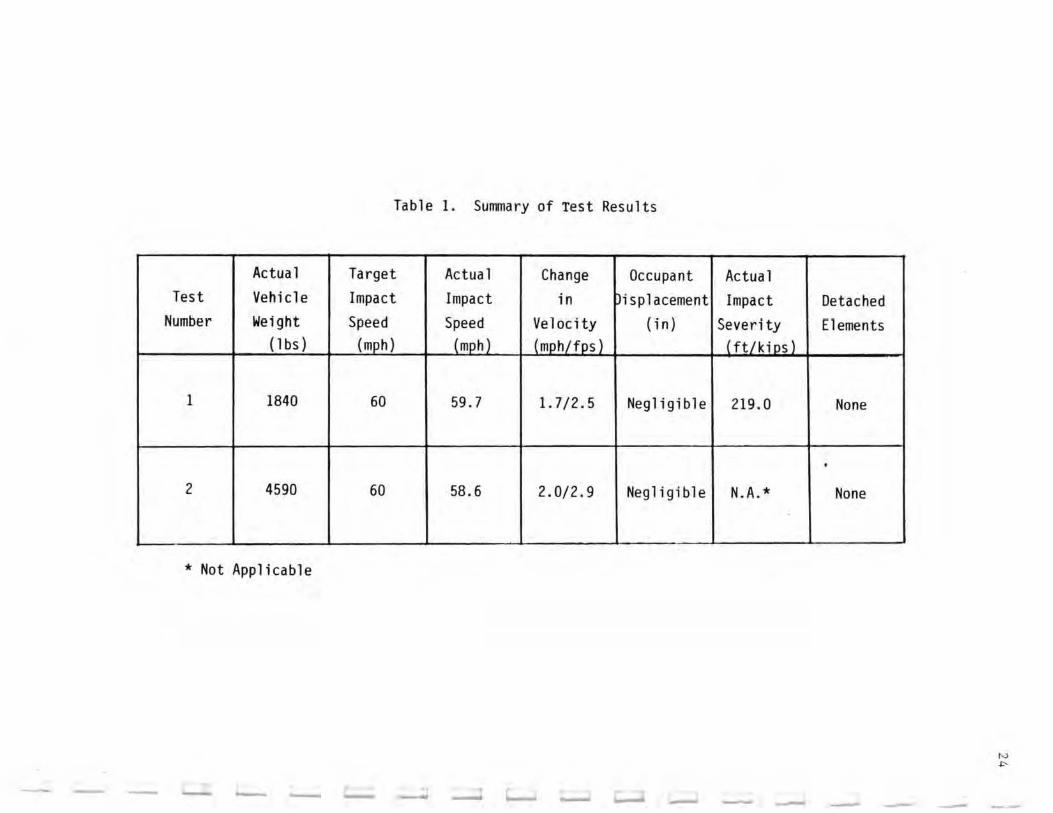
Table 1. Summary of Test Results
Actua I Target Actual Change Occupant Actua I Test Vehicle Impact Impact in isplacement Impact Detac hed
Number Weight Speed Speed Velocity ( in) Sever i ty Elements ( I bs ) (Illl'h) (mph) (mph/fps) ( ft/kil1li
1 1840 60 59.7 1.7/2.5 Negligible 219.0 None
•
2 4590 60 58.6 2.0/2.9 Negligible N.A.* None
* Not Appli cabl e
------ - - - - - -
Test No. 1
The first full-scale crash test was conducted with the 1. 800
lb. vehicle at a target impact speed of 60 mph. The point of
impact was at the center of the bumper. The results of the first
test ar e given in Table 2 and sequential photos taken from the
h igh speed film are shown in Figure 15 with the corresponding
time-event summary given in Table 3.
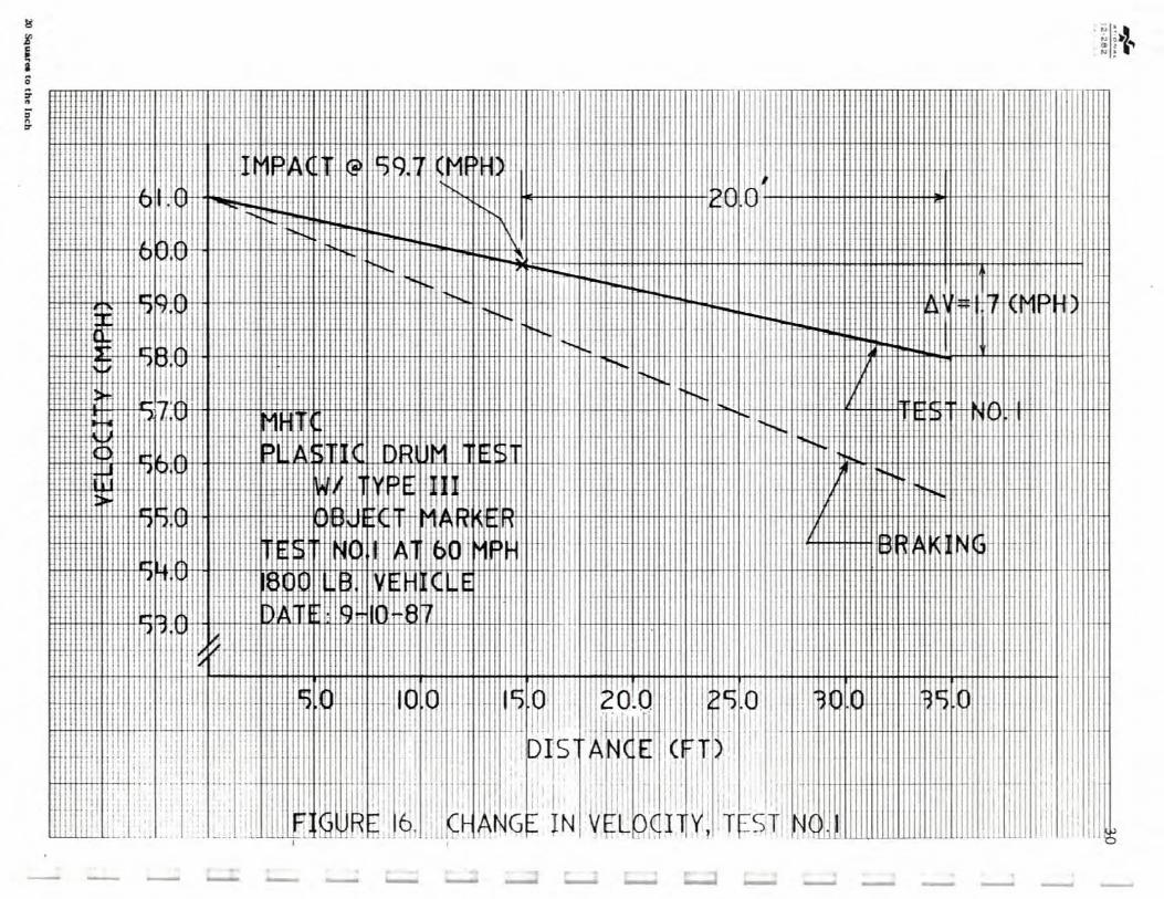
The actual impact speed of the vehicle was 59.7, while the
corresponding change in velocity after impact was 1.7 mph (2. 5
fps) from the point of impact to a point 20 f eet behind the
channelizer. This is shown in Figure 16. After impact , the
vehicle lost contact with the channelizer at approximately 84
milliseconds but regained contact at approximately 247
milliseconds. The vehi cle then continued to push the channelizer
approximately 500 feet until the vehic le stopped.
Upon impact. the channelizer buckled but remained upright
and in front of the vehicle. When the channelizer buckled . th e
object marker deflected down touching the hood momentarily and
then rebounded back to a position very close to its original
position. After close examination. there was no visible evidence
of fracture in the polycarbonate connectors. There was no damage
d one to the test veh icle and the only damage d one to t he fl ex i ble
reflective sheeting was some tearing due to impact. The sheeting
conformed with the defo rma tion of the channelizer without any
evidence of cracking or peeling. Figures 17-19 show photos of
the channelizer. object marker, and test vehicle after the test.
25
During the test , at approximately 50 feet before impa c t, the
hood of the test vehicle unlatched and flew up. After talking t o
the Missouri Highway and Transportation Commission about this
incident. it was decided that the test was still good since this
did not affect the results of the test in any way .
26 I
I I I I I I I I J
I I I I I
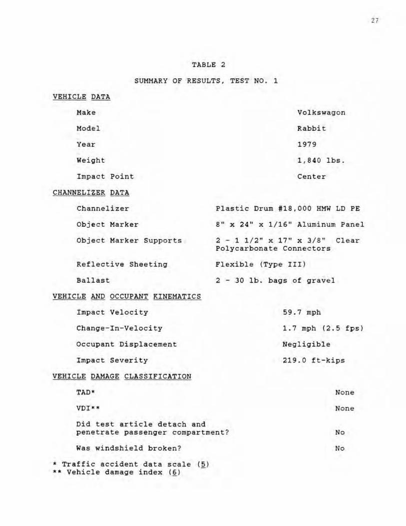
TABLE 2
SUMMARY OF RESULTS, TEST NO . 1
VEHICLE DATA
Hake
Model
Year
Weioht
Impact Point
CHANNELIZER DATA
Channelizer
Object Marker
Object Harker Supports
Reflective Sheeting
Ballast
VEHICLE AND OCCUPANT KINEMATICS
Impact Velocity
Change- In-Veloc ity
Occupant Displacement
Impac t Severity
VEHI CLE DAMAGE CLASSIFICATION
TAD *
VDI-*
Volkswaqon
Rabbit
1979
1 , 84 0 lbs .
Center
Plastic Drum #18 .000 HMW LD PE
8" x 24" x 1 /16 " Aluminum Panel
2 - 1 1 / 2" x 17" x 3 /S " Cl ear Polycarbonate Connectors
Flexible (Type III)
2 - 30 lb . bags o f gravel
59.7 mph
1.7 mph (2.5 fps)
Negligible
219. 0 ft-kips
No n e
None
Did test article deta c h and penetrate pass enoer compartment ? No
Was windshield broken?
* Traffic a cc ident data scale (~)
** Vehicle damaoe index (~)
No
27
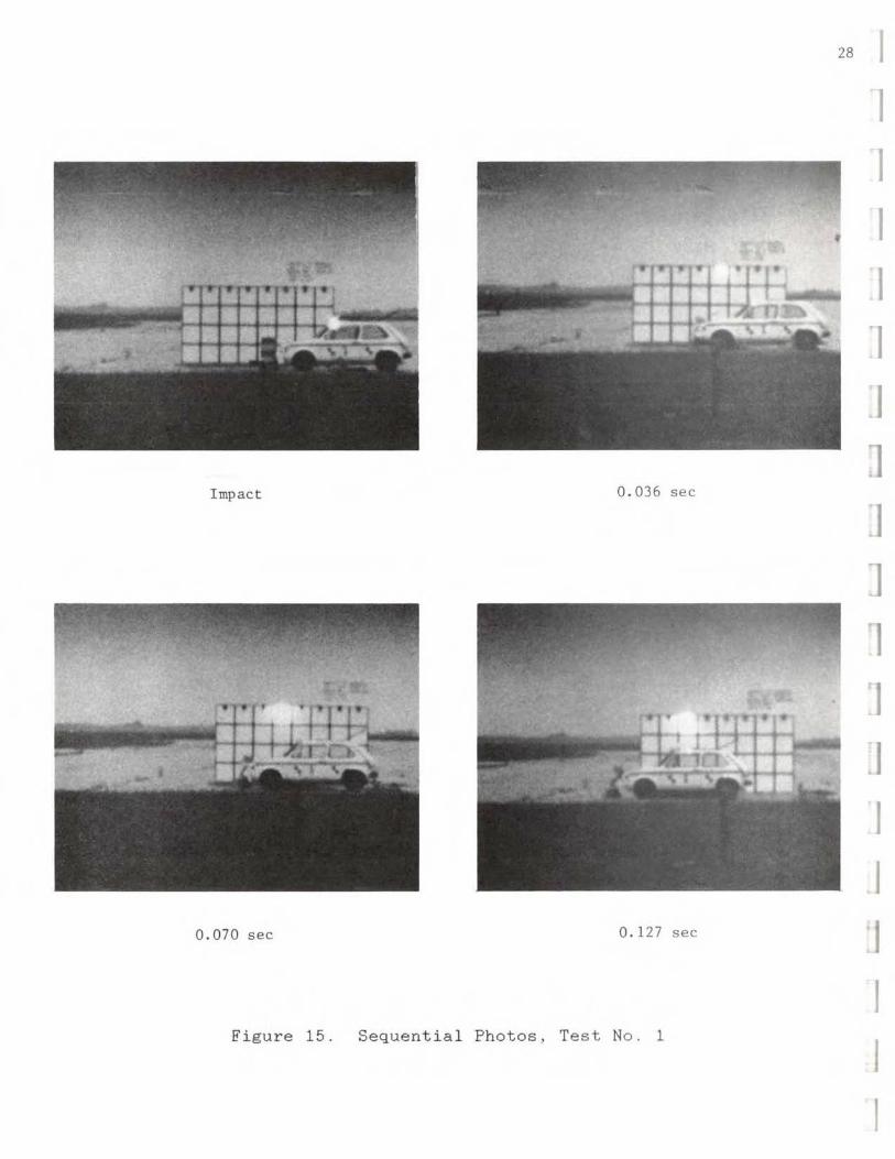
28
Impact 0 . 036 sec
0 . 070 sec 0.127 sec
Figure 15. Sequential Photos, Test No.1
I I I I "I
I J I ]
1 I I
I I J
I
I
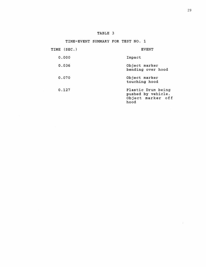
TABLE 3
TIME-EVENT SUMMARY FOR TEST NO. 1
TIME (SEC.)
0.000
0.036
0.070
0.127
EVENT
Impact
Object marker bending over hood
Object marker touching hood.
Plastic Drum being pushed by vehicle. Object marker off hood
29
Id ,
, ,
1 ! I ,
, I
, ,
,
Hiw.1
,
, 1
11m ,
, ,
I
I I , ,
II 1 , I , 'lo! ! Ii;
I I i ~i . I . ',: I , r- 0 ] ~ S , "I
I I +, I N I , ,1 1 , , .,. ,I. , , I' ,
I : !I i 1 .. '
I , I" ,; " I Ii I:' 11
, I
r • , r. . ::. I '.; 1:1
~J " (;T~ : : T~ I ,
, 1 1 r! IJ" I C~ 1 IGf:" IN
,
"
I ~ I , 1
, , T 1 ,
. .. . . - _ .. : _ c: . en ', ;:- "" '- . ~
------ --...-..~------ -
31
Figure 17. Damages to Plastic Drum Channelizer. Test No.1
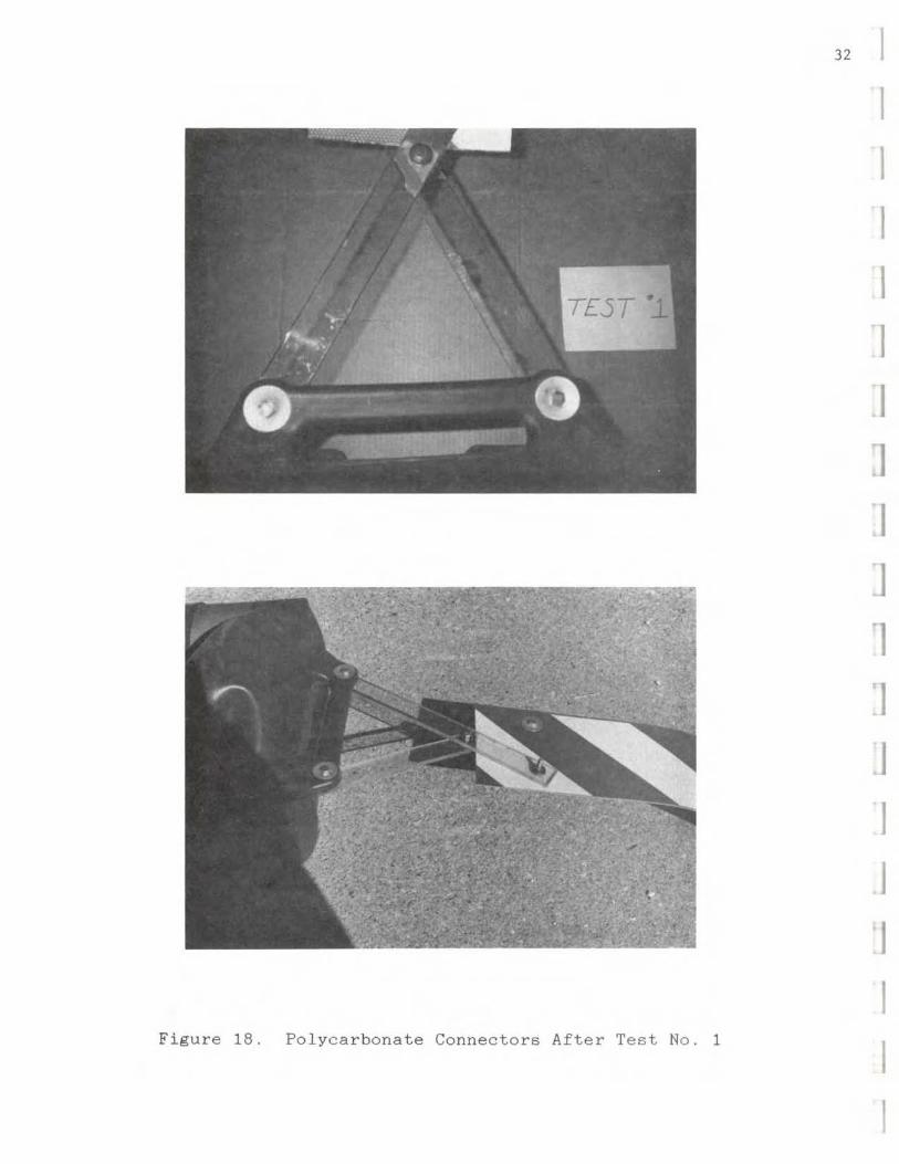
Figure 18. Polycarbonate Connectors After Test No.1
32 I I
I I ']
.I J I ]
1 ']
J
I I I
33
Figure 19. Damage to Test Vehicle, Test No. 1
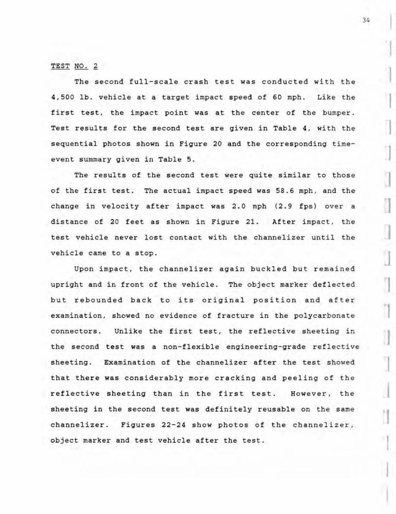
TEST NO. ~
The second full-scale crash test was conducted with the
4,500 lb. vehicle at a target impact speed of 60 mph . Like the
first test , the impact point was at the center of the bumper.
Test results for the second test are given in Table 4 , with the
sequential photos shown in Figure 20 and the corresponding time
event summary given in Table 5 .
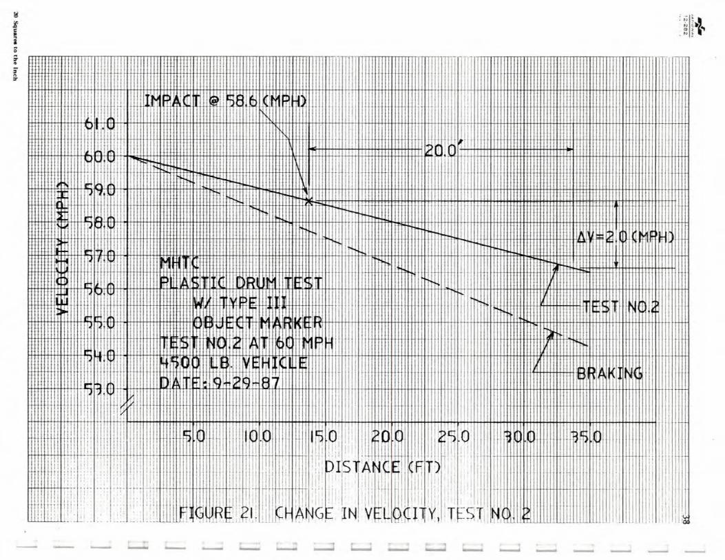
The results of the second test were quite similar to thos e
of the first test. The actual impact speed was 58.6 mph , and the
change in veloci ty after impact was 2.0 mph (2.9 fps) over a
distance of 20 feet as shown in Figure 21 . After impact , the
test vehicle never lost contact with the channelizer until the
vehicle came to a stop.
Upon impact, the channelizer again buckled but remained
upright and in front of the vehicle. The object marker deflected
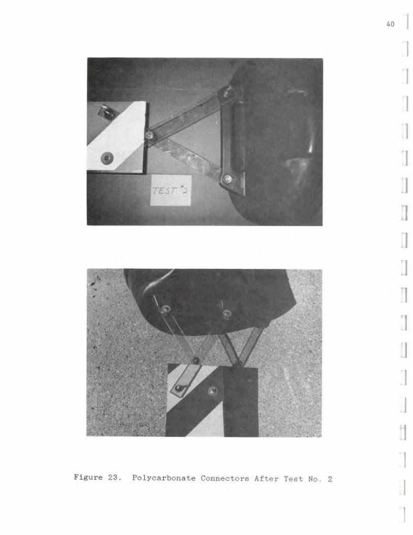
but rebounded back to its original position and after
examination, showed no evidence of fracture in the polycarbonate
connectors.
the second
sheeting.
Unlike the first test. the reflective sheeting in
test was a non-flexible enQ'ineering-Q'rade reflective
Examination of the channelizer after the test showe d
that there was considerably more cracking and peeling of the
reflective sheeting than in the first test. However. the
sheeting in the second test was defini tely reusable on the sam e
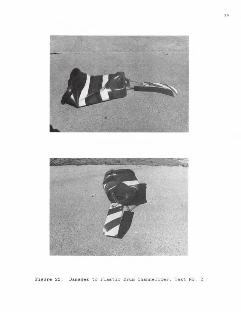
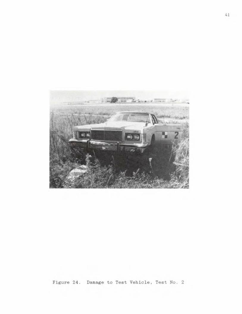
channelizer. Figures 22-24 show photos of the channelizer .
object marker and test vehicle after the test.
34
I
I I I I I ]
I J 1 1
I I
I I I I
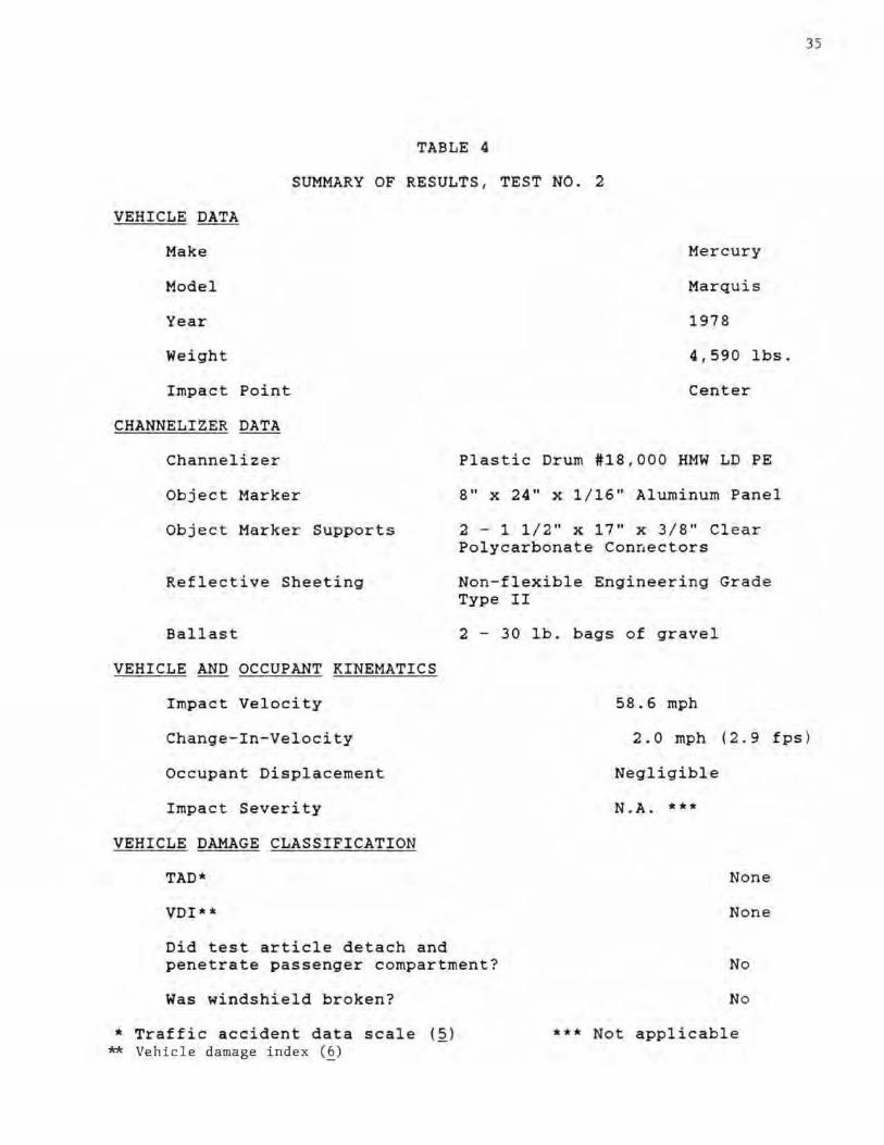
TABLE 4
SUMMARY OF RESULTS , TEST NO. 2
VEHICLE DATA
Make
Hodel
Year
Impact Point
CHANNELIZER DATA
Channelizer
Object Marker
Object Marker Supports
Reflective Sheeting
Ballast
VEHICLE AND OCCUPANT KINEMATICS
Impact Velocity
Me rcury
Marquis
1978
4 f 590 Ibs .
Center
Plastic Drum #18 ,000 HMW LD PE
S" x 24" X 1/16" Aluminum Panel
2 - 1 1 / 2" x 17" x 3 / 8" Clear Polycarbonate Conrlectors
Non-flexible Engineering Grade Type II
2 - 30 lb. bags of gravel
58.6 mph
35
Change-tn-Veloc ity 2.0 mph 12.9 fps )
Occupant Displacement
Impact Severi ty
VEHICLE DAMAGE CLASSIFICATION
TAO·
VO!""·
Did test article detach and penetrate passenger compartment?
Was windshield bro ken?
"" Traffi c accident data scale (~) ** Vehicle damage index (§)
Negligible
N.A. *_a
None
None
No
No
••• Not applicable
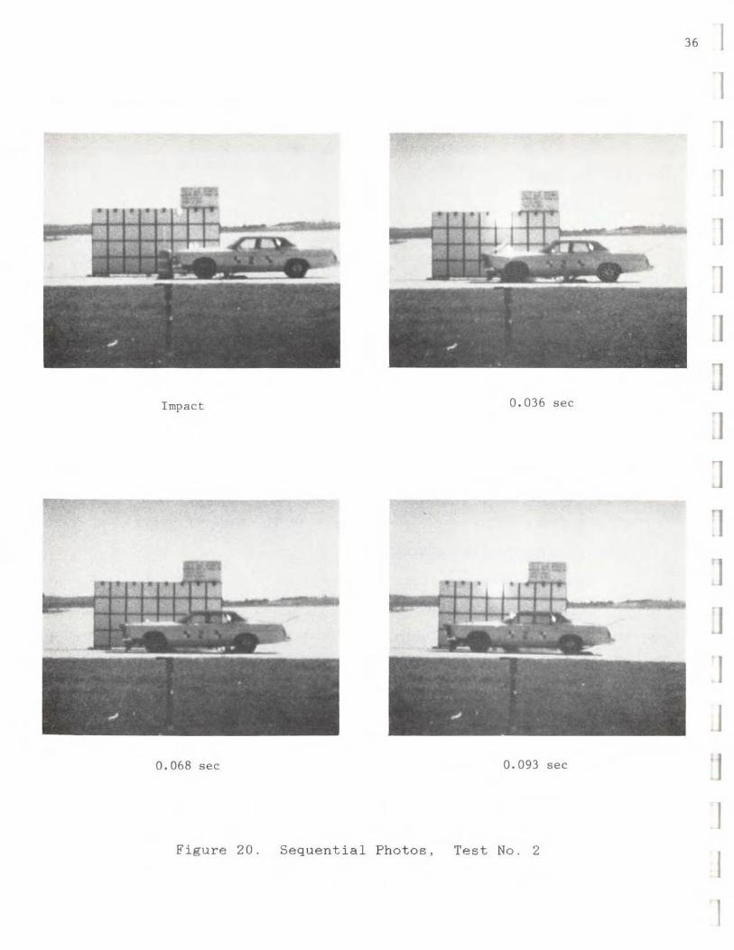
Impact 0 . 036 sec
0.068 sec 0.093 sec
Figure 20. Sequential Photos, Test No.2
36 I I I I I 'J
1
J : 1
J 1 :1 .J 'I j
'J I
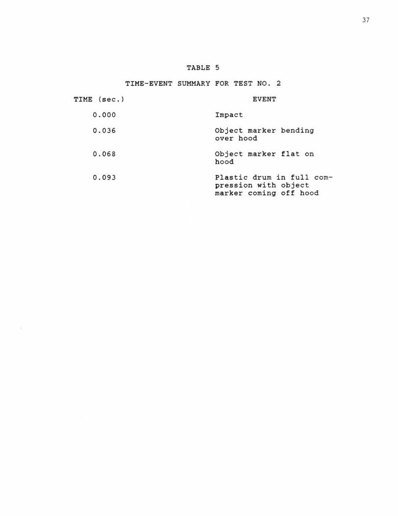
TIME (sec.)
0.000
0.036
0.068
0.093
TABLE 5
TIME-EVENT SUMMARY FOR TEST NO. 2
EVENT
Impact
Object marker bending over hood
Object marker flat on hood
Plastic drum in full compression with object marker coming off hood
37
, I
,
I
, , I .
" j: I'""
Wl...l.!.L1 ...L" " _
I I
, 1111\
,
ilHt , ,
I I
,
,
1 , lillli[
I , I
---- ____ --.:l __ :..--J _____ _
"; ,,.,.,", " I I I
> ' I ' Ii:
- --
39
• •
Figure 22. Damages to Plastic Drum Channelizer. Test No. 2
40
Figure 23. Po lycarbonate Connectors After Test No.2
I I I I I .1 J :1 :J '1 1
1
1
1
1
41
Figure 24. Damage to Test Vehicle. Test No.2
CONCLUSIONS
Two full-scale crash tests were conducted on Plastic Drums
with Type III Object Markers using 1 .800 lb . and 4,500 lb .
vehicles. Analysis of these tests showed that the overall
general performance o f this type of configuration was
satisfactory in accordance
NCHRP 230 (~J, and AASHTO
obtained from the tests:
A. St ructural Adequacy
with
("'J .
the criteria specified in
The following results
both
were
1. The confil1uration displaced at impact in a manner
that was predicted for both tests.
2. I n both tests the object marker remained attached to
the plastic drum. Therefore , no detached el ements
or fragments penetrated, or showed potential to
penetrate , the passenger compartment of the vehicle
and no undue hazard to other traffic was possible .
8. Occupant Risk
1. In b o th tests the vehicle remained upright and
stable durinQ and after impact and showed n o sign of
hazardous redirection. Als o, there were no damages
assessed to the vehicle after either test .
2 . In Test No . 1 , the actual impact severity was within
recommended limits. Fo r Tes t No . 2, the impac t
severity is n ot applicable s ince a 4.50 0 lb. vehic le
is n ot required in testin9 a breakaway or yielding
device .
42
I I I I
1 I I
I
C. Vehicle Trajectory
1. For both tests, the change in velo c ity of the
vehicle was well below the recommended limit of 10. 2
mph (15.0 fps) and the preferable limit of 6.8 mph
110.Ofpsl.
Fr om the above results , it is the recommendation of the
University of Nebraska that the Missour i Highway and
Transport ation Department regard Type III Object Markers on
Plastic Drums as being satisfactory for implementati on in
delineating traffic .
43
TEST ARTICLE RECOMMENDATIONS
Though the tests were successful, these SU~gestions might be
considered for a more effective configuration if cost-eff iciency
permits:
1 . A plastic object marker instead of aluminum could
decrease the chance of passenger compartment penetra tion
if the object marker would happen to detach.
2. Use of 1 bag of sand ( 4 0-6 0 Ibs. ) , instead of 2 bags , for
better chassis clearance .
3. Recommend use of flexible reflective sheeting especially
in cold weather envi r onments instead of non-flexible
reflective sheeting .
4. Do not drill holes i n polycarbonate connectors too big.
This tends to weaken connectors and chance of failure
i nc reases .
44
I J
I I I I
J
I I I I I I
I I
REFERENCES
1. National Cooperative Highway Research Program Report 230
(NC HRP 230) "Recommended Pro cedures for the Safety
Performance Evaluation of Highway Appurtenances , "
Transportation Research Bo ard , Washingt on D.C., March , 1981.
2 . American Ass ociati on of State Highway and Transportation
Offic ials (AASHTO). "Standard Spcifications f or Structural
Supports for Highway Signs, Luminaires, and Traffic Signals , "
Section 7. 1985.
3. J. Hinch . T-L Yang, and R . Owings , "Guidance Systems for
Vehicle Test ing, " ENSCO . Inc ., Springfield. VA , 1986.
4. National Research Council, "Roughness and Skid Resistance , "
Highway Research Board, Bulletin No. 37. 1951.
S . "Vehicle Damage Scale for Traffic Accident Investigators , "
Traffic Accident Data Project Technical Bull etin No . 1 ,
National Safety Council, Chicago , Ill . , 1971.
6. "Collision Deformation Classi fication - SAE J224 Mar 80 , " SAE
Handbook Vol. 4 , Society of Automotive Engineers. Warrendale ,
Penn. , 1985.
45
r r r r
r
r
r r
I
I I I