Embed Size (px)
Citation preview

08/2010 Rev. 4/28/2017 FMDL, MANUAL
Copyright 2017 Vestil Manufacturing Corp. Page 1 of 16
FMDL-Series Single & Double Eagle Beak Fork-Mounted Drum Lifters Use and Maintenance Manual
FMDL-1 (Eagle beak™) FMDL-2 (Eagle Beak™) FPDL-8-L (Base Engaging Plastic Barrel Handler)
FPDL-11-H (Top Engaging Plastic DFDL-3 (Eagle Beak™, Top, & Base Barrel Handler) Engaging Barrel Handler)
Receiving instructions: After delivery, remove the packaging from the product. Inspect the product closely to determine whether it sustained damage during transport. If damage is discovered, record a complete description of it on the bill of lading. If the product is undamaged, discard the packaging. NOTE: The end-user is solely responsible for confirming that product design, installation, use, and maintenance comply with laws, regulations, codes, and mandatory standards applied where the product is used.
Table of Contents Diagrams
Specifications……….……………..…... 2 FMDL-1 parts diagram and bill of materials………………………3 Signal Words…………………………... 2 FMDL-2 parts diagram and bill of materials….…………..…....... 4 Hazards of Improper Use…………...... 2 FPDL-11-H parts diagram and bill of materials…..………….….. 5 Use Instructions……………………….. 11 FPDL-8-L parts diagram and bill of materials…….……….….… 6 Inspections & Maintenance…….……. 11 - 12 DFDL-3 parts diagram and bill of materials………..……..…........ 7 Optional Equipment…………………… 13 - 14 Center of gravity diagrams………….…………………………….. 8 - 10 Limited Warranty……………………… . 15 Labeling diagram…………………………….……………………... 12 Notes……………………………………. 16
Vestil Manufacturing Corp. 2999 North Wayne Street, P.O. Box 507, Angola, IN 46703 Telephone: (260) 665-7586 -or- Toll Free (800) 348-0868
Fax: (260) 665-1339 www.vestilmfg.com Email: [email protected]

08/2010 Rev. 4/28/2017 FMDL, MANUAL
Copyright 2017 Vestil Manufacturing Corp. Page 2 of 16
Specifications: Dimensions and other product specifications appear in the table.
Signal Words: This manual uses SIGNAL WORDS to direct the reader’s attention to statements about uses of the product
that could result in personal injury or property damage. Each signal word correlates with a specific level of seriousness.
Identifies a hazardous situation which, if not avoided, WILL result in DEATH or SERIOUS INJURY. Use of this signal word is limited to the most extreme situations.
Identifies a hazardous situation which, if not avoided, COULD result in DEATH or SERIOUS INJURY.
Identifies practices likely to result in product/property damage, such as operation that might damage the drum lifter.
Hazards of Improper Use:
Improper or careless use of this product might result in serious personal injury., DO NOT exceed the maximum rated load of your lifter (see Label on product; also see table on p. 2). DO NOT use an unsound drum lifter. If any of the following conditions are present, do not use the lifter: 1) missing, broken or significantly bent drum-gripping mechanism; 2) broken, missing, or deformed safety chain; 3) severely damaged/worn fork pockets. Inspect the drum lifter according to the inspection instructions on p. 11-12. Replace each part that fails to pass an inspection. DO NOT use the drum lifter until it is restore to normal condition. No part of your body should ever be beneath any part of the lifter or drum while it is elevated. DO NOT use the lifter to transport anything but drums matched to the specific lifter. (See table on p. 2 (above)). ONLY transport drums slowly. Avoid rough terrain when transporting drums. Jostling might disrupt the grasp on the rim. DO NOT transport drums over rough terrain UNLESS they are secured to the lifter with a ratchet strap. DO NOT modify the drum lifter in any way UNLESS you first obtain written approval from Vestil. Unapproved modifications automatically void the Limited Warranty (p. 15) and could make the lifter unsafe to use. DO NOT use the lifter UNLESS all labels (see Labeling Diagram on p. 12) are present, readable, and undamaged. In order for the Eagle Beak™ mechanism to work properly, each drum (plus contents) must weigh AT LEAST 50
pounds (~22.7kg). The chain is an essential safety-enhancing feature. Wrap the chain around the fork carriage and fasten the free end to
the chain or quick link with no slack.
Model Description Compatible Drums
Capacity
Overall Dimensions Net Weight
FMDL-1 Eagle Beak™ single drum carrier
30 & 55 gallon Open & closed head Steel, plastic, & fiber
1,000 lb. (~455kg)
26½” x 46½” x 29” (67 x 118 x 74)cm
240 lb. (~109kg)
FMDL-2 Eagle Beak™ two drum carrier
30 & 55 gallon Open & closed head Steel, plastic, & fiber
2,000 lb. (~909kg)
42 x 49½ x 29 (107 x 126 x 74)cm
340 lb. (~155kg)
DFDL-3
Deluxe 3-mode drum lifter: Eagle beak, Bottom grip & Top grip
30 & 55 gallon Open & closed head Steel, plastic, & fiber
Eagle Beak™ = 1,000 lb. (~455kg) Bottom grip = 800 lb. (~364kg) Top grip = 1,100 lb. (~455kg)
26½” x 52” x 30” (67 x 132 x 76)cm
313 lb. (~142kg)
FPDL-8-L (“L” = low attachment)
Bottom gripping drum handler for oddly shaped plastic drums
55 gallon Open & closed head Plastic
800 (~364kg)
26½” x 56½” x 23” (67 x 144 x 58)cm
160 lb. (~73kg)
FPDL-11-H (“H” = high attachment)
Top gripping drum handler for oddly shaped plastic drums
30 & 55 gallon Closed head Steel, plastic, & fiber
1100 (~500kg)
26½” x 48½” x 23” (67 x 123 x 58)cm
185 lb. (~84kg)

08/2010 Rev. 4/28/2017 FMDL, MANUAL
Copyright 2017 Vestil Manufacturing Corp. Page 3 of 16
FMDL-1 parts diagram and bill of materials (“Drum gripper assembly” comprises items 9-22)
Item Part No. Description Qty. Item Part No. Description Qty.
1 40-514-008 Weldment, frame 1 12 40-612-004 Pin, clevis, 7/8” x 13/4” long, with washer
1
2 40-514-022 Drum gripper assembly (comprised of items 9-22)
1 13 21-112-003 Pin, clevis, 1/2” x 13/4” long 2
3 65125 Cotter pin, zinc plated, 3/16” x 11/2”
1 14 45286 Clip, hitch pin, 1/8” x 25/8” 3
4 99-112-004 Pin, self-locking quick release 1 15 28-112-031 Pin, clevis, 3/4” x 41/4” 2 5 09-145-018 5/16” chain 56” long 1 16 40-612-006 Weldment, pin, cradle retainer 1
6 08-145-041 Specialty hardware, snap hook, 5/16”
1 17 40-514-011 Weldment, pin bracket 1
7 33-112-023 Pin, clevis 1 18 40-014-054 Weldment, channel 1
8 40-145-008 Strap with ratchet, 6’ long, 2 hooks
1 19 40-146-001 Spring, tension, 61/2” 1
9 40-014-093 Drum cradle 1 20 40-014-029 Frame, bar, formed 1 10 40-016-053 Lower jaw, Eagle Beak™ 1 21 11003 Bolt, hex head, 1/4” - 20 x 3/4” 2 11 40-016-052 Upper jaw, Eagle Beak™ 1 22 37018 Lock nut, 1/4” - 20 2
18
10
11
19
12
NOTE: In order for the Eagle Beak™ mechanism to work properly, the drum and its contents must weigh AT LEAST 50 lb. (~22.7kg).
9
13
14
15
16
Attach hook of ratchet strap
17
20 21 22
Quick link

08/2010 Rev. 4/28/2017 FMDL, MANUAL
Copyright 2017 Vestil Manufacturing Corp. Page 4 of 16
FMDL-2 parts diagram (“Drum gripper assembly” comprises items 10-24)
NOTE: In order for the Eagle Beak™ mechanism to work properly, each drum and its contents must weigh AT LEAST 50 lb. (~22.7kg).
Item Part No. Description Qty. Item Part No. Description Qty.
1 40-514-008 Weldment, frame 1 13 40-612-004 Pin, clevis, 7/8” x 13/4” long, with washer
2
2 40-112-001 Pin, main, clevis, 4 14 21-112-003 Pin, clevis, 1/2” x 13/4” long 4 3 40-514-022 Drum gripper assembly 2 15 40-016-053 Lower jaw, Eagle Beak™ 2
4 40-516-008 Weldment, bracket, mounting bar
1 16 40-514-011 Weldment, pin bracket 2
5 65125 Cotter pin, zinc plated, 3/16” x 11/2”
4 17 40-014-054 Weldment, channel 2
6 99-112-004 Pin, self-locking quick release
2 18 28-112-031 Pin, clevis, 3/4” x 41/4” 4
7 09-145-018 5/16” chain 56” long 1 19 40-612-006 Weldment, pin, cradle retainer
2
8 40-145-008 Specialty hardware, snap hook, 5/16”
1 20 40-014-093 Drum cradle 2
9 40-145-008 Strap with ratchet, 6’ long, 2 hooks
1 21 40-146-001 Spring, tension, 61/2” 2
10 28-112-031 Pin, clevis, 3/4” x 41/4” 2 22 37018 Lock nut, 1/4” - 20 4 11 45286 Clip, hitch pin, 1/8” x 25/8” 6 23 40-014-029 Frame, bar, formed 2
12 40-016-052 Upper jaw, Eagle Beak™ 2 24 11003 Bolt, hex head, 1/4” - 20 x 3/4”
4
Quick link

08/2010 Rev. 4/28/2017 FMDL, MANUAL
Copyright 2017 Vestil Manufacturing Corp. Page 5 of 16
FPDL-11-H parts diagram and bill of materials
Item Part No. Description 1 40-514-008 Eagle Beak™ base frame casting 2 40-514-016 Left side upper drum gripper casting 3 40-512-002 Left side hinge casting 4 40-112-001 1 in. diameter 8-5/8 in. main clevis pin 5 15-112-014 1 in. diameter x 4½ in. pin 6 N/A Fork pockets 7 65125 3/16 in. x 1½ in. cotter pin 8 37-145-004 5/16 in. x 48 in. chain 9 65125 3/16 in. x 1½ in. cotter pin 10 40-514-017 Right side upper drum gripper casting 11 40-512-001 Right side hinge casting
6
10
11
5
9
7
4
3
2
1
8
Quick link

08/2010 Rev. 4/28/2017 FMDL, MANUAL
Copyright 2017 Vestil Manufacturing Corp. Page 6 of 16
FPDL-8-L parts diagram and bill of materials
Item Part No. Description 1 40-514-008 Eagle Beak base frame weldment 2 40-514-020 Left side lower drum gripper weldment 3 40-514-019 Left side lower drum gripper arm weldment 4 40-014-029 Spring steel bar frame 5 11003 ¼ in. – 20 UNC x ¾ in. hex head bolt 6 37018 ¼ in. -20 UNC nylock hex nut 7 11219 ½ in. – 13 UNC x 4 in. hex head bolt 8 37030 ½ in. - 13 UNC nylock hex nut
9 SPMSIRJ ¾ in. (outer diameter) x ½ in. (inner diameter) 8-5/8 in. axle sleeve tube
10 40-112-001 1 in. diameter x 8-5/8 in. main clevis pin 11 65125 3/16 in. x 1½ in. cotter pin 12 40-514-021 Upper side wall support weldment 13 15-115-014 1 in. diameter x 4½ in. retaining pin 14 N/A Fork pockets 15 37-145-001 5/16 in. x 48 in. chain 16 40-514-005 Right side lower drum gripper weldment 17 40-514-009 Right side lower drum gripper arm weldment
16
17
13
7, 8, 9
12
11
10
3
2
1
4
5 & 6
15
14
7, 8, 9
Quick link
08/2010 Rev. 4/28/2017 FMDL, MANUAL
Copyright 2017 Vestil Manufacturing Corp. Page 7 of 16
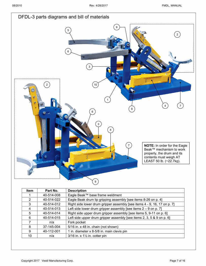
DFDL-3 parts diagrams and bill of materials
Item Part No. Description 1 40-514-008 Eagle Beak™ base frame weldment 2 40-514-022 Eagle Beak drum lip gripping assembly [see items 8-26 on p. 4] 3 40-514-012 Right side lower drum gripper assembly [see items 4 - 9, 16, 17 on p. 7] 4 40-514-013 Left side lower drum gripper assembly [see items 2 – 9 on p. 7] 5 40-514-014 Right side upper drum gripper assembly [see items 5, 9-11 on p. 6] 6 40-514-015 Left side upper drum gripper assembly [see items 2, 3, 5 & 9 on p. 6] 7 n/a Fork pocket 8 37-145-004 5/16 in. x 48 in. chain (not shown) 9 40-112-001 1 in. diameter x 8-5/8 in. main clevis pin 10 n/a 3/16 in. x 1½ in. cotter pin
6
5
10
9
3
4
9
7
2
3
4
6
7
9
2
1
NOTE: In order for the Eagle Beak™ mechanism to work properly, the drum and its contents must weigh AT LEAST 50 lb. (~22.7kg).

08/2010 Rev. 4/28/2017 FMDL, MANUAL
Copyright 2017 Vestil Manufacturing Corp. Page 8 of 16
FMDL-1 center of gravity diagrams
FMDL-2 center of gravity diagrams
Horizontal center of gravity (HCG): 259/16 inches (~64.9 cm) from the open ends of the fork pockets (middle graphic above) and 141/2” inches from the outermost edges of the fork pockets (dotted line in first graphic above). Vertical center of gravity: 65/16 inches (~16.0 cm) from the top of the fork pockets.
Horizontal center of gravity (HCG): 281/16 inches (~71.3 cm) from the open ends of the fork pockets (middle graphic above) and 205/8” (~52.4 cm) from the outermost edges of the drum carrier (dotted line in first graphic above). Vertical center of gravity: 81/16 inches (~20.5 cm) from the top of the fork pockets.
205/8” from outer edges
141/2” from outer edges

08/2010 Rev. 4/28/2017 FMDL, MANUAL
Copyright 2017 Vestil Manufacturing Corp. Page 9 of 16
FPDL-8-L center of gravity diagrams
FPDL-11-H center of gravity diagrams
Horizontal center of gravity (HCG): 27 inches (~68.6cm) from the open ends of the fork pockets; and 14¼ inches (~36.2cm) from the outer edge of each fork pocket (halfway between the fork
pockets).
Vertical center of gravity: 9 inches (~22.9cm) from the bottom of the fork pockets.
Horizontal center of gravity (HCG): 24 inches (~61cm) from the open ends of the fork pockets; and 14¼ inches (~36.2cm) from the outer edge of each fork pocket (halfway between the fork
pockets).
Vertical center of gravity: 15 inches (~38.1cm) from the bottom of the fork pockets.
14 ¼”
14 ¼“

08/2010 Rev. 4/28/2017 FMDL, MANUAL
Copyright 2017 Vestil Manufacturing Corp. Page 10 of 16
Horizontal center of gravity (HCG): 23½ inches (~59.7cm) from the open ends of the fork pockets; and 13¼ inches (~33.7cm) from the outer edge of each fork pocket (halfway between the fork pockets).
Vertical center of gravity: 11 inches (~28cm) from the bottom of the fork pockets.
Horizontal center of gravity (HCG): 21 inches (~53.3cm) from the open ends of the fork pockets; and 13¼ inches (~33.7cm) from the outer edge of each fork pocket (halfway between the fork pockets).
Vertical center of gravity: 11 inches (~23cm) from the bottom of the fork pockets
Horizontal center of gravity (HCG): 25½ inches (~64.8cm) from the open ends of the fork pockets; and 13¼ inches (~33.7cm) from the outer edge of each fork pocket (halfway between the fork pockets).
Vertical center of gravity: 11 inches (~23cm) from the bottom of the fork pockets
DFDL-3 Eagle Beak center of gravity diagram
23½”
11”
11”
13¼”
DFDL-3 lower drum gripping arms center of gravity diagram
21”
13¼”
11”
11”
DFDL-3 upper drum gripping arms center of gravity diagram
25½”
11”
11”
13¼”

08/2010 Rev. 4/28/2017 FMDL, MANUAL
Copyright 2017 Vestil Manufacturing Corp. Page 11 of 16
Use Instructions: Step 1: Adjust the positions of the forks on the carriage of your lift truck to match the fork pockets. Step 2: Mount the drum lifter on the forks of your lift truck by slowly driving forward until the forks contact the ends of the pockets. Step 3: Attach the safety chain to the fork carriage. Wrap the chain around the carriage. Fasten the snap hook to the chain or quick link (see exploded parts diagrams) without slack. The chain must not be able to disconnect from the carriage during use, i.e. slide off of the carriage.
The chain is an essential safety-enhancing feature. Use the chain to connect the drum lifter to the carriage of your fork truck. Wrap the chain around the carriage and fasten the free end to the chain with no slack. The chain will not prevent the drum lifter from sliding off of the forks if it is improperly connected to the fork carriage.
Slowly lower the forks to avoid damaging impacts between the floor/ground and the drum or lifter. Eagle Beak™ and DFDL-3 models: NOTE: In order for the Eagle Beak™ mechanism to work properly, the drum and its contents must weigh AT LEAST 50 lbs. (~22.7kg). Step 4 Engage the selected drum with the lifter: Raise the forks just a few inches off of the ground/floor, and tilt the mast of you fork truck forward. Drive slowly towards the selected drum until the lower jaw of the Eagle Beak™ ((item no. 11 in Fig. 1, p. 4) contacts the side of the drum directly beneath the lip of the drum. Step 5 Grasp the lip of the drum: Slowly raise the forks until the upper jaw engages the top of the drum lip. Continue to raise the forks until the drum is elevated a few inches above the floor/ground. Attach one end of the ratchet strap to one cast loop on the drum side wall casting (Fig. 1, item 26, p. 4). Attach the other end of the ratchet strap to the other cast loop on the side wall casting; then work the ratchet mechanism until the strap is tight. Step 6 Transport the drum: Straighten the mast and transport the drum to the desired unloading location. Raise the forks when/as required by conditions along the travel path. Step 7 Release the drum: Lower the forks until the drum is just a few inches above the floor, and then remove the ratchet strap. Tilt the fork truck mast forward. Slowly lower the forks until the Eagle Beak™ disengages the lip of the drum and the drum is fully supported by the floor/ground. FPDL-11-H and DFDL-3 models: Step 4 Position the fork lift and drum lifter: Raise the forks and adjust the location of the fork lift to position the drum grippers above the top of the drum. Tilt the mast forward, i.e. point the forks toward the floor. Step 5 Position drum grippers: Lower the forks; the drum grippers will slide over the lip of the drum. Position the grippers below the lip or the middle rim as desired. Step 6 Transport the drum: Straighten the mast and raise the forks until the gripper engages the lip or rim, and then slowly raise the forks until the drum is elevated a few inches above the floor. Tilt the mast back; then transport the drum to the desired location. Step 7 Release the drum: First tilt the mast forward and then slowly lower the forks until the drum is fully supported by the floor. To finish disengaging the drum, back the fork truck away from it. FPDL-8-L and DFDL-3 models: Step 4 Position fork lift and drum lifter: Adjust the mast position so that the drum grippers are parallel to the ground. Slightly elevate the forks above the floor. Step 5 Prepare the engage the drum: Adjust the position of the fork truck to center the drum lifter on the drum; then drive forward until the side of the drum contacts the upper side wall support weldment (FIG. 4, item no. 4, on p. 7). Step 6 Transport drum: Raise the forks until the lower drum gripper weldments (FIG. 4, item no’s 2 & 16, on p. 7) engage the base of the drum. Raise the drum a few inches above the ground; secure it to the lifter by attaching the ratchet strap to the cast loops of the side wall support (FIG. 4, item no. 12, p. 7); then transport it to the desired unloading point. Step 7 Release the drum: First tilt the mast forward; then slowly lower the forks until the drum is fully supported by the ground/floor. Slowly back the fork lift away from the drum until the drum and lifter disengage.
Inspections & Maintenance: Regular inspections and maintenance are necessary for the lifter to remain in normal condition. Before using it
for the first time, create a written record that describes the appearance of the drum gripping mechanism, drum cradle, pins, fork pockets, the safety chain, and the frame. Install the lifter on the forks of your forklift and use it to lift a drum.. Record your observations about how the gripping mechanism engages the drum. Lower the drum and record your observations. This written record establishes “normal condition”. When conducting future inspections compare those observations with the written record to determine whether a component is in normal condition or requires repair or replacement.

08/2010 Rev. 4/28/2017 FMDL, MANUAL
Copyright 2017 Vestil Manufacturing Corp. Page 12 of 16
Before each use, inspect the following components: 1. Safety chain and snap hook (attached to the free end of the safety chain): confirm that the spring latch
automatically closes securely against the hook. DO NOT use the lifter if the hook, chain, cold shut (the loop welded to the lifter frame, which connects to one end of the chain), or ratchet strap loop castings are damaged.
2. Labels: all labels should be readable and located as shown in FIG. 6. If a label(s) is unreadable or missing, contact Vestil to order a replacement.
At least once per month, inspect: 1. Fasteners (hardware):
Bolts, nuts, washers, pins, cotter pins; Chain and snap hook.
2. Fork pockets: confirm that each pocket is structurally sound, i.e. no significant corrosion. Do not use the lifter if the fork pockets are structurally unsound
3. Welds: confirm that all welds are intact. 4. Drum grippers, Eagle Beak® upper and/or lower jaw, fork pockets, and supporting frame: must be undamaged.
For example, no deformations, warps, or cracks. 5. Overall condition of drum lifter: the structure should be clean, square and rigid, and free of rust and corrosion.
Remove dirt and debris. Do not use the lifter if the supporting frame and/or one or both grippers are excessively rusted or corroded.
Labeling diagram: The drum lifter should always be labeled as shown in the diagram below. Replace any label that is missing,
damaged, or not easily readable, e.g. significantly faded.
Optional equipment:
B: Label 218 (on fork pocket)
B C
C: Label 287 (on fork pocket)
A
A: Label 485

08/2010 Rev. 4/28/2017 FMDL, MANUAL
Copyright 2017 Vestil Manufacturing Corp. Page 13 of 16
Cushioned drum cradles are available for FMDL-style drum lifters.FMDL-1-LDS-R3 and FMDL-2-LDS-R3 include cradles equipped with rollers. Models FMDL-1-LDS-B1 and FMDL-2-LDS-B1 include cradles equipped with rubber belts. All 4 cushioned models are shown in the diagrams.
FMDL-1-LDS-B1
FMDL-2-LDS-B1

08/2010 Rev. 4/28/2017 FMDL, MANUAL
Copyright 2017 Vestil Manufacturing Corp. Page 14 of 16
FMDL-1-LDS-R3
FMDL-2-LDS-R3

08/2010 Rev. 4/28/2017 FMDL, MANUAL
Copyright 2017 Vestil Manufacturing Corp. Page 15 of 16
LIMITED WARRANTY
Vestil Manufacturing Corporation (“Vestil”) warrants this product to be free of defects in material and workmanship during the warranty period. Our warranty obligation is to provide a replacement for a defective original part if the part is covered by the warranty, after we receive a proper request from the warrantee (you) for warranty service.
Who may request service? Only a warrantee may request service. You are a warrantee if you purchased the product from Vestil or from an authorized distributor AND Vestil has been fully paid.
What is an “original part”? An original part is a part used to make the product as shipped to the warrantee.
What is a “proper request”? A request for warranty service is proper if Vestil receives: 1) a photocopy of the Customer Invoice that displays the shipping date; AND 2) a written request for warranty service including your name and phone number. Send requests by any of the following methods:
Mail Fax Email Vestil Manufacturing Corporation (260) 665-1339 [email protected] 2999 North Wayne Street, PO Box 507 Phone Angola, IN 46703 (260) 665-7586
In the written request, list the parts believed to be defective and include the address where replacements should be delivered.
What is covered under the warranty? After Vestil receives your request for warranty service, an authorized representative will contact you to determine whether your claim is covered by the warranty. Before providing warranty service, Vestil may require you to send the entire product, or just the defective part or parts, to its facility in Angola, IN. The warranty covers defects in the following original dynamic components: motors, hydraulic pumps, electronic controllers, switches and cylinders. It also covers defects in original parts that wear under normal usage conditions (“wearing parts”), such as bearings, hoses, wheels, seals, brushes, and batteries.
How long is the warranty period? The warranty period for original dynamic components is 90 days. For wearing parts, the warranty period is 90 days. The warranty periods begin on the date when Vestil ships the product to the warrantee. If the product was purchased from an authorized distributor, the periods begin when the distributor ships the product. Vestil may, at its sole discretion, extend the warranty periods for products shipped from authorized distributors by up to 30 days to account for shipping time.
If a defective part is covered by the warranty, what will Vestil do to correct the problem? Vestil will provide an appropriate replacement for any covered part. An authorized representative of Vestil will contact you to discuss your claim.
What is not covered by the warranty? 1. Labor; 2. Freight; 3. Occurrence of any of the following, which automatically voids the warranty:
Product misuse; Negligent operation or repair; Corrosion or use in corrosive conditions; Inadequate or improper maintenance; Damage sustained during shipping; Accidents involving the product; Unauthorized modifications: DO NOT modify the product IN ANY WAY without first receiving written authorization
from Vestil. Modification(s) might make the product unsafe to use or might cause excessive and/or abnormal wear.
Do any other warranties apply to the product? Vestil Manufacturing Corp. makes no other express warranties. All implied warranties are disclaimed to the extent allowed by law. Any implied warranty not disclaimed is limited in scope to the terms of this Limited Warranty.

08/2010 Rev. 4/28/2017 FMDL, MANUAL
Copyright 2017 Vestil Manufacturing Corp. Page 16 of 16
NOTES: