Embed Size (px)
Citation preview
Full parallax three-dimensionaldisplay from Kinect v1 and v2
Seokmin HongGenaro SaavedraManuel Martinez-Corral
Seokmin Hong, Genaro Saavedra, Manuel Martinez-Corral, “Full parallax three-dimensional display fromKinect v1 and v2,” Opt. Eng. 56(4), 041305 (2017), doi: 10.1117/1.OE.56.4.041305.
Full parallax three-dimensional display fromKinect v1 and v2
Seokmin Hong,* Genaro Saavedra, and Manuel Martinez-CorralUniversity of Valencia, 3-D Imaging and Display Laboratory, Department of Optics, Burjassot, E-46100, Spain
Abstract. We exploit the two different versions of Kinect, v1 and v2, for the calculation of microimages projectedonto integral-imaging displays. Our approach is based on composing a three-dimensional (3-D) point cloud froma captured depth map and RGB information. These fused 3-D maps permit to generate an integral image afterprojecting the information through a virtual pinhole array. In our analysis, we take into account that each of theKinect devices has its own inherent capacities and individualities. We illustrate our analysis with some imagingexperiments, provide the distinctive differences between the two Kinect devices, and finally conclude that Kinectv2 allows the display of 3-D images with very good resolution and with full parallax. © 2016 Society of Photo-OpticalInstrumentation Engineers (SPIE) [DOI: 10.1117/1.OE.56.4.041305]
Keywords: three-dimensional display; integral imaging; point cloud; Kinect v1; Kinect v2.
Paper 161256SS received Aug. 9, 2016; accepted for publication Sep. 28, 2016; published online Oct. 19, 2016.
1 IntroductionRecently, integral imaging (InI) has been considered as oneof the potential technologies in order to display real worldscenes. Conventionally, the pickup stage of InI is performedby inserting a tiny lens array in front of a two-dimensional(2-D) imaging sensor. A remarkable feature of the InItechnique is that every captured picture involves differentperspectives information. The reason is that optical rays pro-ceeding from three-dimensional (3-D) objects are collectedby every lens, and recorded by the imaging sensor with dif-ferent incidence angles. Here, we name as microimage theimage recorded behind any microlens. The whole array ofmicroimages is named here as the integral picture. Whenthe integral picture is projected onto an InI monitor, it canprovide the observers with 3-D floating color images, whichhave full-parallax and quasicontinuous perspective.1–4 Manyresearchers have applied the InI technique in differentfields.5–15
Meanwhile, there are various depth-sensing 3-D imagingtechniques announced to record 3-D scenes. Among them,one interesting technique is stereovision, which exploitsthe disparity information from two arranged cameras.16,17
However, in the past few years, the use of technologiesrelated to infrared (IR) light sensors18–21 has become increas-ingly popular. Especially the Kinect device from Microsoftthat profits from IR lighting technology in the case of depthacquisition. Until now, there are two different versions ofKinect. The main commercial specifications of them aredescribed in Table 1. The Kinect allows acquiring RGB, IR,and depth maps in real-time with a high frame rate. For thatreason, many researchers are now interested in its capability.As is well known, both sensors have many different featuresfor obtaining a dense depth map. The Kinect v1 uses astructured IR dot-pattern emitter and IR camera to evaluatedepth information. In comparison, the Kinect v2 utilizestime-of-flight (ToF) technology, which consists of emitting
IR flashes at high frequency. Having IR light that reflectsfrom most 3-D surfaces, the sensor can evaluate the depthdistance by measuring the light’s returning time.22,23 Themain drawback of both, Kinect v1 and Kinect v2, is that theyare limited for long range. Comparable results, but with anextended range, has been demonstrated but with a differenttechnology.24
2 Calibration of Kinect v1 and v2As seen in Table 1, the commercial specifications of theKinects do not reflect all the characteristics of those devices.In order to extend this information, and also to confirmsome commercial parameters, we performed a number ofexperiments.
2.1 Coupled Area at the Scene
The aim of our first experiment was to find the common areain the scene, and to check both the RGB and IR camera’sfields of view (FOV) through empirical parameters. For thisexperiment, we first defined the standpoint of Kinect devicesas the position of the nut where the tripod is screwed in. Thenwe defined an optical axis and set the Kinect frontal faceparallel to the target. As the common target, we choose achessboard pattern, which has simple and repetitive shapesand permits to easily detect feature points. Most of all, theregularized pattern influence improves the accuracy of thecalibration’s result.25 We find common correspondencefeatures in each captured scene and calculate correlationparameters, which are called homography, projectivity, orprojective transformation. These parameters represent a gen-eral plane-to-plane correlation equation in a projective plane.These values convince to map from one camera’s 2-D viewto another.26–29 Figure 1 shows the common area in bothKinect devices.
*Address all correspondence to: Seokmin Hong, E-mail: [email protected] 0091-3286/2016/$25.00 © 2016 SPIE
Optical Engineering 041305-1 April 2017 • Vol. 56(4)
Optical Engineering 56(4), 041305 (April 2017)

2.2 Comparison of Field of View with EmpiricalParameters
Next, we attempt to measure, for both Kinects, the RGB andIR FOVs. Actually, the official specification did not mentionthe RGB FOV. For that reason, we measured the FOVs withtwo methods: (a) estimate FOV by calibrated camera param-eters and (b) physical calibration progress at a certain dis-tance. First, we use the calibrated camera parametersreported in Ref. 22 and calculate each FOV by using Eq. (1).In this equation, Cw and Ch are the RGB and IR physicalimaging sensor sizes, and f is a focal length. Rw and Rhare the calculated angles in the horizontal and vertical
directions.30 Finally, we derived FOVs from the referencedparameters (see Table 2).
EQ-TARGET;temp:intralink-;e001;326;730Rw ¼ 2 arctan
�Cw
2f
�; Rh ¼ 2 arctan
�Ch
2f
�: (1)
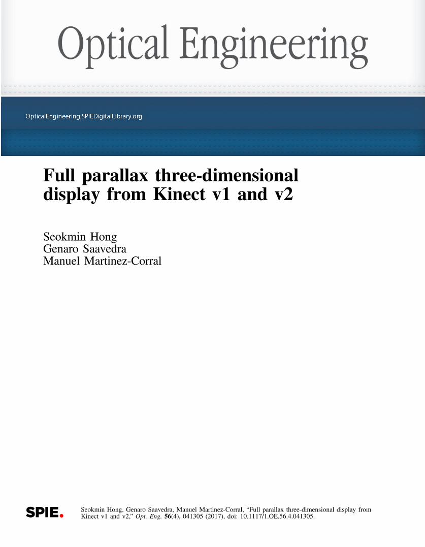
Second, we set up an environment in order to measure theFOV in a physical calibration progress. We placed the cam-era in a perpendicular direction from the wall within a certaindistance. Then we stitched a piece of retroreflective (RR)sheet to the wall in the border area of the captured scene.Here, the IR camera can only capture an IR light and discardother light sources. Again, the IR camera cannot detect dif-fusing surfaces that are normal to the optical axis. In contrast,RR sheets can directly reflect IR light to the camera and, as aresult, provide an easy way to verify a target’s position in theIR camera’s scene. From now, we already know about theZ-axis and width distance in millimeters. Then we can deriveboth horizontal and vertical FOVs using trigonometric func-tion calculations. We illustrate this progress in Fig. 2 and putour empirical results in Table 3.
One thing worth noting is that through our experiment weconfirmed some important issues. First, the two types ofFOVs do not map properly. Some regions overlap, but notall parts from the scene are covered. Second, the announcedFOV information from commercial specifications is for theIR camera. Third, we have proven that the commercialparameters are reliable. Parameters reported in Ref. 22 arealso reliable, but not in the case of the FOVof the IR cameraof Kinect v1.
3 Microimages Generation fromThree-Dimensional Point Cloud
The aim of this research is to analyze and compare the twoKinect devices when they are concentrated in a specific
Table 1 Comparison between Kinect v1 and v2 specifications.
List Kinect v1 Kinect v2
Released (year) 2010 2014
RGB camera (pixel) 640 × 480(max: 1280 × 960Þ
1920 × 1080
FPS in RGB camera 30 (Max: 12) 30 (low-light: 15)
IR camera (pixel) 640 × 480 512 × 424
FPS in IR camera 30 30
Depth acquisitionmethod
Structured IRlight pattern
ToF
Depth distance (mm) 800–4000 500–4500
Horizontal FOV (deg) 57 70
Vertical FOV (deg) 43 60
Fig. 1 Kinect v1 and v2 overlapped region in the captured scene. Green rectangle represents the RGBview and the red rectangle is the IR view.
Optical Engineering 041305-2 April 2017 • Vol. 56(4)
Hong, Saavedra, and Martinez-Corral: Full parallax three-dimensional display from Kinect v1 and v2
application: the calculation of the collection of microimagesthat are projected onto an InI monitor with an aim of display-ing 3-D images with full-parallax.
The procedure for calculation of microimages is as fol-lows. First, the captured RGB and depth map images(see Fig. 3) are modified into a 3-D point cloud, followingRef. 6. From this result (see Fig. 4), we confirmed that Kinectv2 is able to capture the depth information of further points.Moreover, the density of point cloud data is also different.The Kinect v1, for instance, has a specific layer structure [seeFig. 4(a)]. But Kinect v2 provides more dense depth infor-mation without any regularized figuration [see Fig. 4(b)].The most impressive feature from Kinect v2 is that thisdevice can acquire depth information of slender targets,reflective surfaces, or even transparent objects comparedwith Kinect v1. In the third step of the procedure, we placeda virtual pinhole array (VPA) at a certain distance from thepoint cloud.
An important thing is that the VPA position decides thefront and rear volumes in the displayed 3-D scenes. Due tothis, the VPA position defines what we call the “referenceplane” of the 3-D scene. In this experiment, we placed theVPA just behind the second chair. We assigned each 3-Dpoint into microimages by back projection through the pin-holes, as in Ref. 31. The main issue is that different featuresof the 3-D point clouds fully reflect into generated microi-mages. It is important to point out that the calculation of themicroimages needs to take into account the parameters of theInI display. Specifically, we need to know the number ofmicrolenses, their pitch, the gap, and the number of pixelsbehind any microlens. Figure 5 shows the calculated micro-images, which are ready for projection into the InI displaysystem described below. These two figures clearly show thedifferences of the two devices.
4 Experimental Results of DisplayedThree-Dimensional Image
In order to display our microimages, we used the Samsungtablet SM-T700 (359 pixels∕inch) as a high definition dis-play, and a microlens array (MLA) consisting of 113 × 113lenslets of focal length fL ¼ 3.3 mm and pitch p ¼ 1.0 mm(Model 630 from Fresnel Technology). The resulting micro-images are composed of 15 pixels. The gap between themicrolenses and the display was fixed to g ¼ 49.5 px.Finally, the full size of integral picture is 1695 × 1695 pixels.After fixing and aligning the MLA with the tablet, theresulting InI monitor displayed 3-D images with fullparallax.
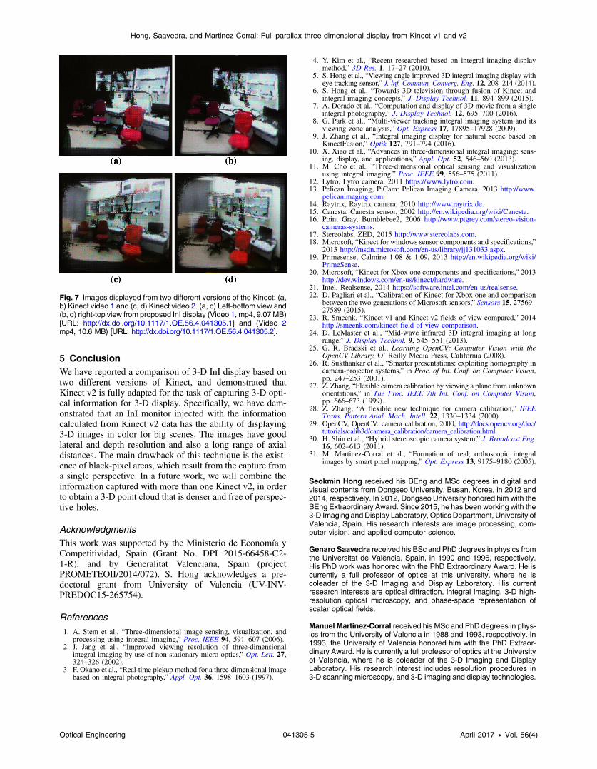
To demonstrate the three-dimensionality of the displayedimages, we implemented the setup shown in Fig. 6, andrecorded pictures of the InI display from many vertical andhorizontal perspectives. From the pictures’ collection, wecomposed two videos, one for the Kinect v1 (Video 1) andthe other for the Kinect v2 (Video 2). Additionally, weexcerpted a pair of frames from any video. These framesare shown and compared in Fig. 7. This figure confirmsthat Kinect v2 is a very powerful tool which can be appliednot only for the versatile management of videogames butalso for the display of 3-D images with full parallax, goodlateral depth, and for a long range of axial distances.
Table 3 Kinect v1 and v2’s RGB, IR camera’s FOV calculation resultfrom physical calibrating progress.
List Kinect v1 Kinect v2
Camera type RGB IR RGB IR
Width distance (mm) 1177 1101 1814 1394
Height distance (mm) 912 816 1029 1143
Z -axis distance (mm) 1000 1000 1000 1000
Calculated FOV:horizontal (deg)
60.95 57.67 84.42 69.75
Calculated FOV:vertical (deg)
49.03 44.39 54.45 59.50
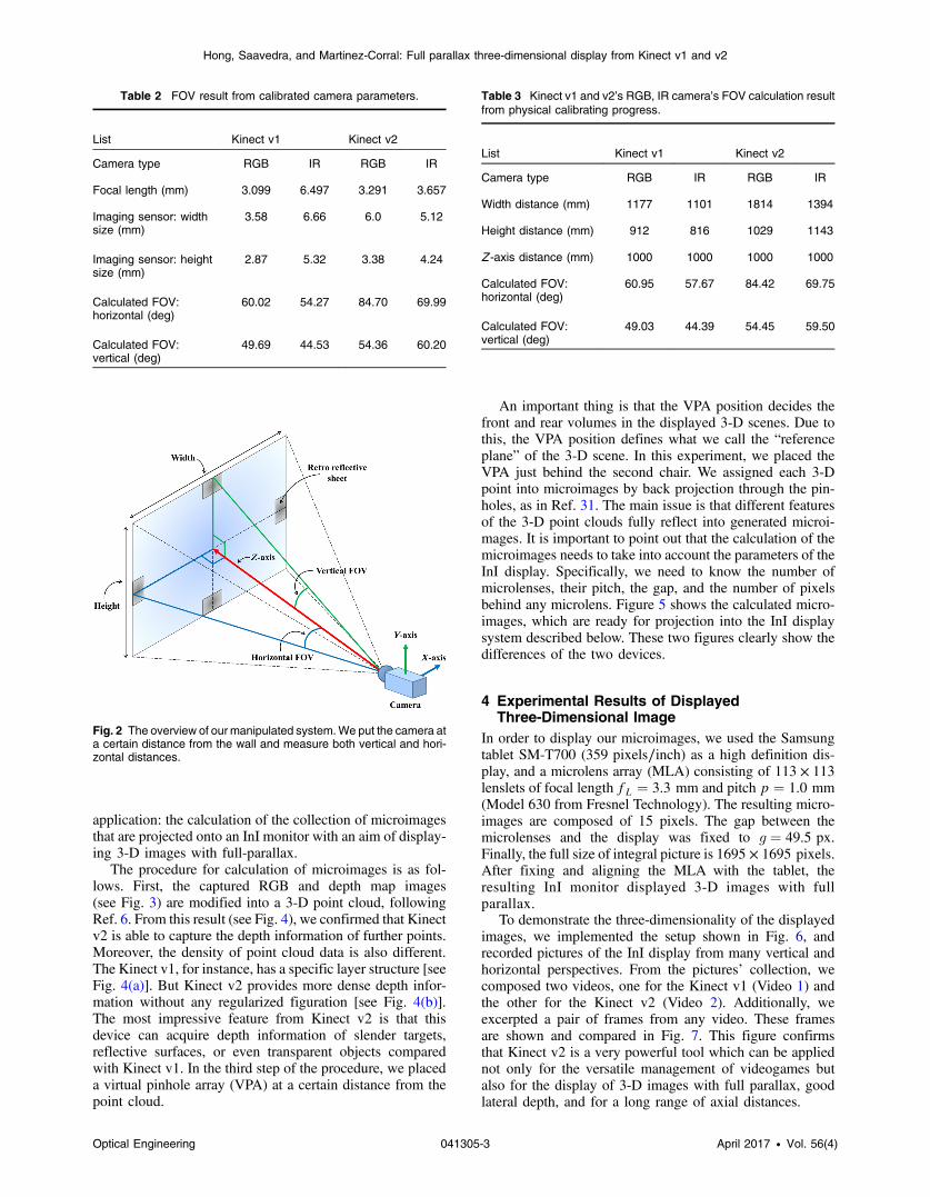
Table 2 FOV result from calibrated camera parameters.
List Kinect v1 Kinect v2
Camera type RGB IR RGB IR
Focal length (mm) 3.099 6.497 3.291 3.657
Imaging sensor: widthsize (mm)
3.58 6.66 6.0 5.12
Imaging sensor: heightsize (mm)
2.87 5.32 3.38 4.24
Calculated FOV:horizontal (deg)
60.02 54.27 84.70 69.99
Calculated FOV:vertical (deg)
49.69 44.53 54.36 60.20
Fig. 2 The overview of our manipulated system.We put the camera ata certain distance from the wall and measure both vertical and hori-zontal distances.
Optical Engineering 041305-3 April 2017 • Vol. 56(4)
Hong, Saavedra, and Martinez-Corral: Full parallax three-dimensional display from Kinect v1 and v2
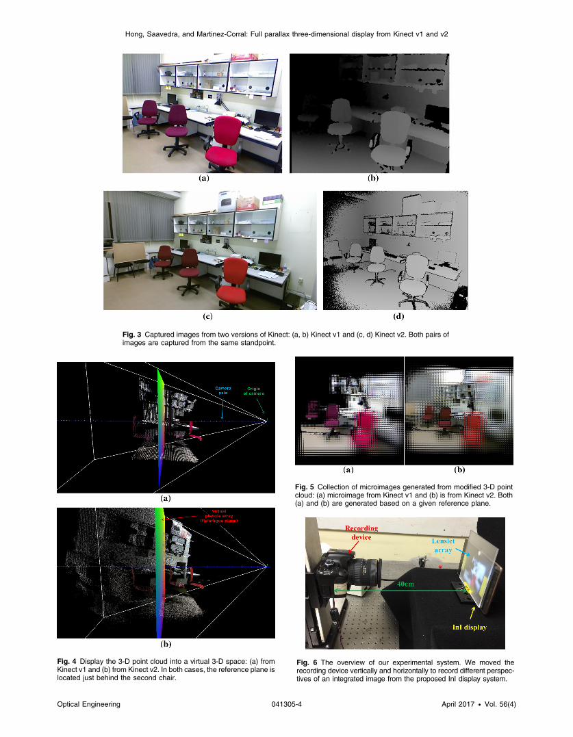
Fig. 3 Captured images from two versions of Kinect: (a, b) Kinect v1 and (c, d) Kinect v2. Both pairs ofimages are captured from the same standpoint.
Fig. 4 Display the 3-D point cloud into a virtual 3-D space: (a) fromKinect v1 and (b) from Kinect v2. In both cases, the reference plane islocated just behind the second chair.
Fig. 5 Collection of microimages generated from modified 3-D pointcloud: (a) microimage from Kinect v1 and (b) is from Kinect v2. Both(a) and (b) are generated based on a given reference plane.
Fig. 6 The overview of our experimental system. We moved therecording device vertically and horizontally to record different perspec-tives of an integrated image from the proposed InI display system.
Optical Engineering 041305-4 April 2017 • Vol. 56(4)
Hong, Saavedra, and Martinez-Corral: Full parallax three-dimensional display from Kinect v1 and v2
5 ConclusionWe have reported a comparison of 3-D InI display based ontwo different versions of Kinect, and demonstrated thatKinect v2 is fully adapted for the task of capturing 3-D opti-cal information for 3-D display. Specifically, we have dem-onstrated that an InI monitor injected with the informationcalculated from Kinect v2 data has the ability of displaying3-D images in color for big scenes. The images have goodlateral and depth resolution and also a long range of axialdistances. The main drawback of this technique is the exist-ence of black-pixel areas, which result from the capture froma single perspective. In a future work, we will combine theinformation captured with more than one Kinect v2, in orderto obtain a 3-D point cloud that is denser and free of perspec-tive holes.
AcknowledgmentsThis work was supported by the Ministerio de Economía yCompetitividad, Spain (Grant No. DPI 2015-66458-C2-1-R), and by Generalitat Valenciana, Spain (projectPROMETEOII/2014/072). S. Hong acknowledges a pre-doctoral grant from University of Valencia (UV-INV-PREDOC15-265754).
References
1. A. Stem et al., “Three-dimensional image sensing, visualization, andprocessing using integral imaging,” Proc. IEEE 94, 591–607 (2006).
2. J. Jang et al., “Improved viewing resolution of three-dimensionalintegral imaging by use of non-stationary micro-optics,” Opt. Lett. 27,324–326 (2002).
3. F. Okano et al., “Real-time pickup method for a three-dimensional imagebased on integral photography,” Appl. Opt. 36, 1598–1603 (1997).
4. Y. Kim et al., “Recent researched based on integral imaging displaymethod,” 3D Res. 1, 17–27 (2010).
5. S. Hong et al., “Viewing angle-improved 3D integral imaging display witheye tracking sensor,” J. lnf. Commun. Converg. Eng. 12, 208–214 (2014).
6. S. Hong et al., “Towards 3D television through fusion of Kinect andintegral-imaging concepts,” J. Display Technol. 11, 894–899 (2015).
7. A. Dorado et al., “Computation and display of 3D movie from a singleintegral photography,” J. Display Technol. 12, 695–700 (2016).
8. G. Park et al., “Multi-viewer tracking integral imaging system and itsviewing zone analysis,” Opt. Express 17, 17895–17928 (2009).
9. J. Zhang et al., “Integral imaging display for natural scene based onKinectFusion,” Optik 127, 791–794 (2016).
10. X. Xiao et al., “Advances in three-dimensional integral imaging: sens-ing, display, and applications,” Appl. Opt. 52, 546–560 (2013).
11. M. Cho et al., “Three-dimensional optical sensing and visualizationusing integral imaging,” Proc. IEEE 99, 556–575 (2011).
12. Lytro, Lytro camera, 2011 https://www.lytro.com.13. Pelican Imaging, PiCam: Pelican Imaging Camera, 2013 http://www.
pelicanimaging.com.14. Raytrix, Raytrix camera, 2010 http://www.raytrix.de.15. Canesta, Canesta sensor, 2002 http://en.wikipedia.org/wiki/Canesta.16. Point Gray, Bumblebee2, 2006 http://www.ptgrey.com/stereo-vision-
cameras-systems.17. Stereolabs, ZED, 2015 http://www.stereolabs.com.18. Microsoft, “Kinect for windows sensor components and specifications,”
2013 http://msdn.microsoft.com/en-us/library/jj131033.aspx.19. Primesense, Calmine 1.08 & 1.09, 2013 http://en.wikipedia.org/wiki/
PrimeSense.20. Microsoft, “Kinect for Xbox one components and specifications,” 2013
http://dev.windows.com/en-us/kinect/hardware.21. Intel, Realsense, 2014 https://software.intel.com/en-us/realsense.22. D. Pagliari et al., “Calibration of Kinect for Xbox one and comparison
between the two generations of Microsoft sensors,” Sensors 15, 27569–27589 (2015).
23. R. Smeenk, “Kinect v1 and Kinect v2 fields of view compared,” 2014http://smeenk.com/kinect-field-of-view-comparison.
24. D. LeMaster et al., “Mid-wave infrared 3D integral imaging at longrange,” J. Display Technol. 9, 545–551 (2013).
25. G. R. Bradski et al., Learning OpenCV: Computer Vision with theOpenCV Library, O’ Reilly Media Press, California (2008).
26. R. Sukthankar et al., “Smarter presentations: exploiting homography incamera-projector systems,” in Proc. of Int. Conf. on Computer Vision,pp. 247–253 (2001).
27. Z. Zhang, “Flexible camera calibration by viewing a plane from unknownorientations,” in The Proc. IEEE 7th Int. Conf. on Computer Vision,pp. 666–673 (1999).
28. Z. Zhang, “A flexible new technique for camera calibration,” IEEETrans. Pattern Anal. Mach. Intell. 22, 1330–1334 (2000).
29. OpenCV, OpenCV: camera calibration, 2000, http://docs.opencv.org/doc/tutorials/calib3d/camera_calibration/camera_calibration.html.
30. H. Shin et al., “Hybrid stereoscopic camera system,” J. Broadcast Eng.16, 602–613 (2011).
31. M. Martinez-Corral et al., “Formation of real, orthoscopic integralimages by smart pixel mapping,” Opt. Express 13, 9175–9180 (2005).
Seokmin Hong received his BEng and MSc degrees in digital andvisual contents from Dongseo University, Busan, Korea, in 2012 and2014, respectively. In 2012, Dongseo University honored him with theBEng Extraordinary Award. Since 2015, he has been working with the3-D Imaging and Display Laboratory, Optics Department, University ofValencia, Spain. His research interests are image processing, com-puter vision, and applied computer science.
Genaro Saavedra received his BSc and PhD degrees in physics fromthe Universitat de València, Spain, in 1990 and 1996, respectively.His PhD work was honored with the PhD Extraordinary Award. He iscurrently a full professor of optics at this university, where he iscoleader of the 3-D Imaging and Display Laboratory. His currentresearch interests are optical diffraction, integral imaging, 3-D high-resolution optical microscopy, and phase-space representation ofscalar optical fields.
Manuel Martinez-Corral received his MSc and PhD degrees in phys-ics from the University of Valencia in 1988 and 1993, respectively. In1993, the University of Valencia honored him with the PhD Extraor-dinary Award. He is currently a full professor of optics at the Universityof Valencia, where he is coleader of the 3-D Imaging and DisplayLaboratory. His research interest includes resolution procedures in3-D scanning microscopy, and 3-D imaging and display technologies.
Fig. 7 Images displayed from two different versions of the Kinect: (a,b) Kinect video 1 and (c, d) Kinect video 2. (a, c) Left-bottom view and(b, d) right-top view from proposed InI display (Video 1, mp4, 9.07 MB)[URL: http://dx.doi.org/10.1117/1.OE.56.4.041305.1] and (Video 2mp4, 10.6 MB) [URL: http://dx.doi.org/10.1117/1.OE.56.4.041305.2].
Optical Engineering 041305-5 April 2017 • Vol. 56(4)
Hong, Saavedra, and Martinez-Corral: Full parallax three-dimensional display from Kinect v1 and v2