Embed Size (px)
Citation preview

FULL LIFT TYPE VALVE AT 10% OVERPRESSURE
W H AT I S A F U L L
L I F T T Y P E VA LV E ?
A Full Lift Type Valve is a
relief valve which attains
full stable lift at only 10%
overpressure. Like all
Groth Pressure/Vacuum
Relief Valves, the Full Lift
Type Valve is a modulating
valve which offers near
zero blowdown, meaning it
reseats near set pressure.
These performance
capabilities are possible
due to the harmonization
of the nozzle, seating, and
pallet areas such that the
valve will achieve stable lift
at only 10% above the set
pressure/vacuum.
1800A SeriesFor applications requiring low emissions and operation near Maximum Allowable Working Pressure (MAWP)
Advantages of the Groth Full Lift Type Valve
Compared to Standard Pressure / Vacuum
Relief Valve
FULL OPEN CAPACITY AT 10%
OVERPRESSURE
The most notable advantage of this valve is
it being fully open at 10% overpressure while
standard Pressure / Vacuum Relief Valves achieve
full open capacity at 100% overpressure. The use
of a Full Lift Type Valve allows the user to select
the valve set pressure (vacuum) within 10% of
the tank Maximum Allowable Working Pressure
(Vacuum). This is important because operation
near the tank design pressure greatly reduces the
breathing losses of the product in the tank.
Features
• Available in 2” (DN 50) through 12” (DN 300)
flange sizes
• Stable Full lift at 10% overpressure
• Modulating action
• Near zero blowdown (reseats near set pressure)
• Able to achieve set pressure/vacuum very
close to tank maximum allowable working
pressure/vacuum
Benefits
• Ability to operate process closer to Tank
MAWP, increasing operating range of process
• Minimal seat leakage to prevent fugitive
emission and conserve tank product
• Narrow valve operating range (from seal to full
open) maximizes tank operating range and
reduces total vapor emissions
• Stable lift ensures that the venting
requirements of the process are reliably met
• Reduced seat leakage, low overpressure, and
near zero blowdown characteristics to allow
for process maintenance, minimal product loss
and better tank corrosion maintenance
Materials
• Available in aluminum, carbon steel and
stainless steel
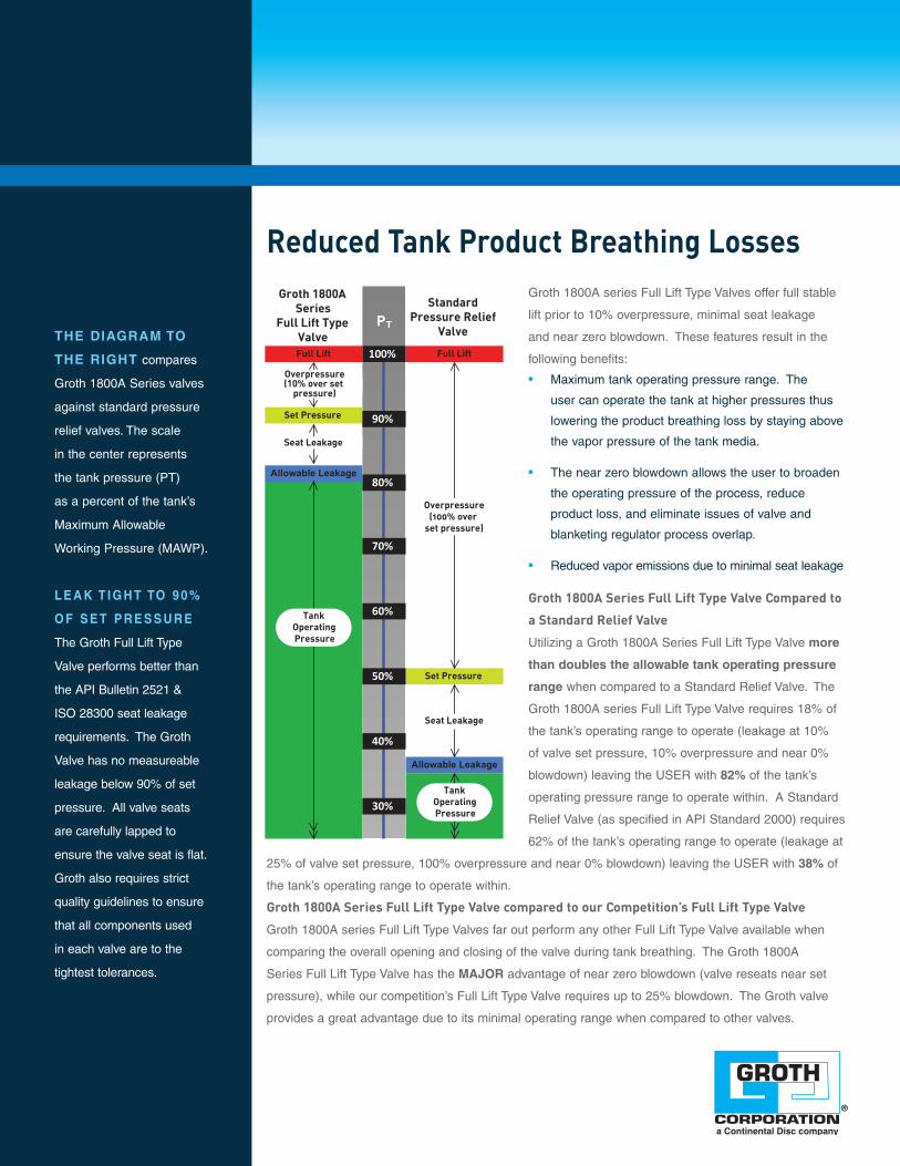
Reduced Tank Product Breathing LossesGroth 1800A series Full Lift Type Valves offer full stable
lift prior to 10% overpressure, minimal seat leakage
and near zero blowdown. These features result in the
following benefits:
• Maximum tank operating pressure range. The
user can operate the tank at higher pressures thus
lowering the product breathing loss by staying above
the vapor pressure of the tank media.
• The near zero blowdown allows the user to broaden
the operating pressure of the process, reduce
product loss, and eliminate issues of valve and
blanketing regulator process overlap.
• Reduced vapor emissions due to minimal seat leakage
Groth 1800A Series Full Lift Type Valve Compared to
a Standard Relief Valve
Utilizing a Groth 1800A Series Full Lift Type Valve more
than doubles the allowable tank operating pressure
range when compared to a Standard Relief Valve. The
Groth 1800A series Full Lift Type Valve requires 18% of
the tank’s operating range to operate (leakage at 10%
of valve set pressure, 10% over pressure and near 0%
blowdown) leaving the USER with 82% of the tank’s
operating pressure range to operate within. A Standard
Relief Valve (as specified in API Standard 2000) requires
62% of the tank’s operating range to operate (leakage at
25% of valve set pressure, 100% over pressure and near 0% blowdown) leaving the USER with 38% of
the tank’s operating range to operate within.
Groth 1800A Series Full Lift Type Valve compared to our Competition’s Full Lift Type Valve
Groth 1800A series Full Lift Type Valves far out perform any other Full Lift Type Valve available when
comparing the overall opening and closing of the valve during tank breathing. The Groth 1800A
Series Full Lift Type Valve has the MAJOR advantage of near zero blowdown (valve reseats near set
pressure), while our competition’s Full Lift Type Valve requires up to 25% blowdown. The Groth valve
provides a great advantage due to its minimal operating range when compared to other valves.
THE DIAGRAM TO
THE RIGHT compares
Groth 1800A Series valves
against standard pressure
relief valves. The scale
in the center represents
the tank pressure (PT)
as a percent of the tank’s
Maximum Allowable
Working Pressure (MAWP).
L E A K T I G H T TO 9 0 %
O F S E T P R E S S U R E
The Groth Full Lift Type
Valve performs better than
the API Bulletin 2521 &
ISO 28300 seat leakage
requirements. The Groth
Valve has no measureable
leakage below 90% of set
pressure. All valve seats
are carefully lapped to
ensure the valve seat is flat.
Groth also requires strict
quality guidelines to ensure
that all components used
in each valve are to the
tightest tolerances.
Set Pressure
Set Pressure
Full Lift
Groth 1800A Series
Full Lift Type Valve
StandardPressure Relief
Valve
90%
100%
80%
70%
60%
PT
Full Lift
Allowable Leakage
Allowable Leakage
Overpressure(10% over set
pressure)
Overpressure(100% over
set pressure)
Seat Leakage
Seat Leakage
50%
40%
30%
Tank Operating Pressure
Tank Operating Pressure

3 © 2009 Groth Corporation
Pressure Relief CapacityModel 1800A PRESSURE RELIEF
Set Pressure Size
In WC OSI 2”(DN50)
3”(DN75)
4”(DN100)
6”(DN150)
8”(DN200)
10”(DN250)
12” (DN300)
Flow Capacity at 10% Over-pressure and 60°F [1000 SCFH]
0.9 0.5 3.29 7.25 12.5 28.3 49.1 77.3 111
1.0 0.6 3.54 7.79 13.4 30.5 52.7 83.1 119
2.0 1.2 5.00 11.0 19.0 43.1 74.6 118 169
3.0 1.7 6.13 13.5 23.2 52.7 91.3 144 206
4.0 2.3 7.07 15.6 26.8 60.9 105 166 238
6.0 3.5 8.66 19.1 32.9 74.6 129 204 292
8.0 4.6 10.0 22.0 37.9 86.1 149 235 337
10.0 5.8 11.2 24.6 42.4 96.2 167 263 377
12.0 6.9 12.2 27.0 46.4 105 182 288 413
13.9 8.0 13.1 29.0 49.9 113 196 309 443
Model 1800A PRESSURE RELIEF
Set Pressure Size
mm Wc mbar 2”(DN50)
3”(DN75)
4”(DN100)
6”(DN150)
8”(DN200)
10”(DN250)
12” (DN300)
Flow Capacity at 10% Over-pressure and 0°C [1000 NCMH]
25 2.45 0.102 0.225 0.388 0.88 1.52 2.40 3.44
50 4.90 0.145 0.318 0.548 1.24 2.15 3.40 4.87
75 7.35 0.177 0.390 0.671 1.52 2.64 4.16 5.96
100 9.80 0.204 0.450 0.775 1.76 3.05 4.80 6.89
125 12.3 0.228 0.503 0.867 1.97 3.41 5.37 7.70
150 14.7 0.250 0.551 0.949 2.15 3.73 5.88 8.43
200 19.6 0.289 0.636 1.10 2.49 4.31 6.79 9.74
250 24.5 0.323 0.711 1.22 2.78 4.81 7.59 10.9
300 29.4 0.354 0.779 1.34 3.04 5.27 8.31 11.9
350 34.3 0.382 0.841 1.45 3.29 5.69 8.97 12.9
Flow capacity is certified by Groth Corporation based on actual tests conducted in compliance with API
Standard 2000 and ISO 28300:2008.
InletFlg
ALength
BHeight
CWidth
Metric Metric Metric Metric
2” 135/8” 13” 9½”
50 mm 346 mm 330 mm 241 mm
3” 18” 135/8” 11½”
30 mm 457 mm 346 mm 292 mm
4” 19¾” 157/8” 13”
100 mm 503 mm 403 mm 130 mm
6” 27¾” 22¼” 19”
150 mm 704 mm 565 mm 482 mm
8” 337/8” 263/8” 235/8”
200 mm 860 mm 669 mm 600 mm
10” 407/8” 287/8” 30¾”
250 mm 1038 mm 733 mm 781 mm
12” 46” 327/8” 36”
300 mm 1165 mm 835 mm 914 mm
MODEL 1800Pressure/Vacuum Relief Valve

Vacuum Relief CapacityModel 1800A VACUUM RELIEF
Set Vacuum Size
In WC OSI 2”(DN50)
3”(DN75)
4”(DN100)
6”(DN150)
8”(DN200)
10”(DN250)
12” (DN300)
Flow Capacity at 10% Over-vacuum and 60°F [1000 SCFH]
0.9 0.5 1.57 3.54 6.30 14.2 25.2 39.4 56.7
1.0 0.6 1.69 3.81 6.80 15.2 27.1 42.3 61.0
2.0 1.2 2.39 5.37 9.60 21.5 38.2 60.0 86.0
3.0 1.7 2.92 6.6 11.7 26.3 46.7 73.0 105
4.0 2.3 3.37 7.60 13.5 30.3 53.9 84.0 121
6.0 3.5 4.11 9.30 16.5 37.0 66.0 103 148
8.0 4.6 4.74 10.7 18.9 42.6 76.0 118 170
10.0 5.8 5.28 11.9 21.1 47.5 84.0 132 190
12.0 6.9 5.80 13.0 23.1 51.9 92.0 144 208
13.9 8.0 6.20 13.9 24.7 55.6 99.0 154 222
Model 1800A VACUUM RELIEF
Set Vacuum Size
mm Wc mbar 2”(DN50)
3”(DN75)
4”(DN100)
6”(DN150)
8”(DN200)
10”(DN250)
12” (DN300)
Flow Capacity at 10% Over-vacuum and 0°C [1000 NCMH]
25 2.45 0.049 0.110 0.196 0.44 0.780 1.22 1.76
50 4.90 0.069 0.155 0.276 0.620 1.10 1.73 2.48
75 7.35 0.084 0.190 0.338 0.760 1.35 2.11 3.04
100 9.80 0.097 0.219 0.389 0.880 1.56 2.43 3.50
125 12.3 0.109 0.245 0.435 0.980 1.74 2.72 3.91
150 14.7 0.119 0.267 0.475 1.07 1.90 2.97 4.28
200 19.6 0.137 0.308 0.547 1.23 2.19 3.42 4.93
250 24.5 0.153 0.343 0.610 1.37 2.44 3.81 5.49
300 29.4 0.167 0.375 0.670 1.50 2.67 4.17 6.00
350 34.3 0.179 0.404 0.720 1.62 2.87 4.49 6.46
Flow capacity is certified by Groth Corporation based on actual tests conducted in compliance with API
Standard 2000 and ISO 28300:2008.
MODEL 1800Pressure/Vacuum Relief Valve

Pressure Relief CapacityModel 1820A PRESSURE RELIEF
Set Pressure Size
In WC OSI 2”(DN50)
3”(DN75)
4”(DN100)
6”(DN150)
8”(DN200)
10”(DN250)
12” (DN300)
Flow Capacity at 10% Over-pressure and 60°F [1000 SCFH]
0.9 0.5 2.52 5.55 9.50 21.7 37.5 59.1 85.0
1.0 0.6 2.71 5.96 10.3 23.3 40.3 63.6 91.0
2.0 1.2 3.83 8.40 14.5 32.9 57.0 90.0 129
3.0 1.7 4.68 10.3 17.8 40.3 69.8 110 158
4.0 2.3 5.41 11.9 20.5 46.6 81.0 127 182
6.0 3.5 6.62 14.6 25.1 57.0 99.0 156 223
8.0 4.6 7.60 16.8 29.0 65.8 114 180 258
10.0 5.8 8.50 18.8 32.4 73.6 127 201 288
12.0 6.9 9.40 20.6 35.5 81.0 140 220 316
13.9 8.0 10.1 22.2 38.1 87.0 150 236 339
Model 1820A PRESSURE RELIEF
Set Pressure Size
mm Wc mbar 2”(DN50)
3”(DN75)
4”(DN100)
6”(DN150)
8”(DN200)
10”(DN250)
12” (DN300)
Flow Capacity at 10% Over-pressure and 0°C [1000 NCMH]
25 2.45 0.078 0.172 0.297 0.673 1.17 1.84 2.63
50 4.90 0.111 0.244 0.419 0.952 1.65 2.60 3.73
75 7.35 0.135 0.298 0.513 1.17 2.02 3.18 4.56
100 9.80 0.156 0.344 0.593 1.35 2.33 3.67 5.27
125 12.3 0.175 0.385 0.663 1.50 2.60 4.11 5.89
150 14.7 0.191 0.422 0.726 1.65 2.85 4.50 6.45
200 19.6 0.221 0.487 0.838 1.90 3.29 5.19 7.45
250 24.5 0.247 0.544 0.937 2.13 3.68 5.80 8.32
300 29.4 0.270 0.596 1.03 2.33 4.03 6.36 9.12
350 34.3 0.292 0.643 1.11 2.51 4.35 6.86 9.84
Flow capacity is certified by Groth Corporation based on actual tests conducted in compliance with API
Standard 2000 and ISO 28300:2008.
MODEL 1820Pressure/Vacuum Relief Valve
InletFlg
ALength
BHeight
CWidth
Metric Metric Metric Metric2” 14¼” 125/8” 7½”
50 mm 361 mm 320 mm 191 mm3” 18” 151/8” 9”
30 mm 457 mm 384 mm 229 mm4” 19¼” 18¼” 11”
100 mm 489 mm 463 mm 279 mm6” 26¼” 23¾” 13½”
150 mm 673 mm 603 mm 343 mm8” 32½” 28½” 16”
200 mm 826 mm 723 mm 406 mm10” 37¾” 34¼” 19”
250 mm 959 mm 876 mm 483 mm12” 42¾” 391/8” 21”
300 mm 1086 mm 993 mm 533 mm
InletFlg
D E
Metric Metric Metric2” 7” 5½”
50 mm 178 mm 140 mm3” 81/8” 6”
30 mm 206 mm 152 mm4” 9½” 6½”
100 mm 241 mm 165 mm6” 12¾” 8½”
150 mm 324 mm 216 mm8” 15¼” 10¾”
200 mm 387 mm 273 mm10” 18” 12½”
250 mm 457 mm 318 mm12” 205/8” 15”
300 mm 524 mm 381 mm

Vacuum Relief CapacityModel 1820A VACUUM RELIEF
Set Vacuum Size
In WC OSI 2”(DN50)
3”(DN75)
4”(DN100)
6”(DN150)
8”(DN200)
10”(DN250)
12” (DN300)
Flow Capacity at 10% Over-vacuum and 60°F [1000 SCFH]
0.9 0.5 1.57 3.54 6.30 14.2 25.2 39.4 56.7
1.0 0.6 1.69 3.81 6.80 15.2 27.1 42.3 61.0
2.0 1.2 2.39 5.37 9.60 21.5 38.2 60.0 86.0
3.0 1.7 2.92 6.60 11.7 26.3 46.7 73.0 105
4.0 2.3 3.37 7.60 13.5 30.3 53.9 84.0 121
6.0 3.5 4.11 9.30 16.5 37.0 66.0 103 148
8.0 4.6 4.74 10.7 18.9 42.6 76.0 118 170
10.0 5.8 5.28 11.9 21.1 47.5 84.0 132 190
12.0 6.9 5.80 13.0 23.1 51.9 92.0 144 208
13.9 8.0 6.20 13.9 24.7 55.6 99.0 154 222
Model 1820A VACUUM RELIEF
Set Vacuum Size
mm Wc mbar 2”(DN50)
3”(DN75)
4”(DN100)
6”(DN150)
8”(DN200)
10”(DN250)
12” (DN300)
Flow Capacity at 10% Over-vacuum and 0°C [1000 NCMH]
25 2.45 0.049 0.110 0.196 0.440 0.78 1.22 1.76
50 4.90 0.069 0.155 0.276 0.620 1.10 1.73 2.48
75 7.35 0.084 0.190 0.338 0.760 1.35 2.11 3.04
100 9.80 0.097 0.219 0.389 0.880 1.56 2.43 3.50
125 12.3 0.109 0.245 0.435 0.980 1.74 2.72 3.91
150 14.7 0.119 0.267 0.475 1.07 1.90 2.97 4.28
200 19.6 0.137 0.308 0.547 1.23 2.19 3.42 4.93
250 24.5 0.153 0.343 0.610 1.37 2.44 3.81 5.49
300 29.4 0.167 0.375 0.670 1.50 2.67 4.17 6.00
350 34.3 0.179 0.404 0.720 1.62 2.87 4.49 6.46
Flow capacity is certified by Groth Corporation based on actual tests conducted in compliance with API
Standard 2000 and ISO 28300:2008.
MODEL 1820Pressure/Vacuum Relief Valve

Pressure Relief CapacityModel 1830A PRESSURE RELIEF
Set Pressure Size
In WC OSI 2”(DN50)
3”(DN75)
4”(DN100)
6”(DN150)
8”(DN200)
10”(DN250)
12” (DN300)
Flow Capacity at 10% Over-pressure and 60°F [1000 SCFH]
0.9 0.5 3.29 7.25 12.5 28.3 49.1 77.3 111
1.0 0.6 3.54 7.79 13.4 30.5 52.7 83.1 119
2.0 1.2 5.00 11.0 19.0 43.1 74.6 118 169
3.0 1.7 6.13 13.5 23.2 52.7 91.3 144 206
4.0 2.3 7.07 15.6 26.8 60.9 105 166 238
6.0 3.5 8.66 19.1 32.9 74.6 129 204 292
8.0 4.6 10.0 22.0 37.9 86.1 149 235 337
10.0 5.8 11.2 24.6 42.4 96.2 167 263 377
12.0 6.9 12.2 27.0 46.4 105 182 288 413
13.9 8.0 13.1 29.0 49.9 113 196 309 443
Model 1830A PRESSURE RELIEF
Set Pressure Size
mm Wc mbar 2”(DN50)
3”(DN75)
4”(DN100)
6”(DN150)
8”(DN200)
10”(DN250)
12” (DN300)
Flow Capacity at 10% Over-pressure and 0°C [1000 NCMH]
25 2.45 0.102 0.225 0.388 0.880 1.52 2.40 3.44
50 4.90 0.145 0.318 0.548 1.24 2.15 3.40 4.87
75 7.35 0.177 0.390 0.671 1.52 2.64 4.16 5.96
100 9.80 0.204 0.450 0.775 1.76 3.05 4.80 6.89
125 12.3 0.228 0.503 0.867 1.97 3.41 5.37 7.70
150 14.7 0.250 0.551 0.949 2.15 3.73 5.88 8.43
200 19.6 0.289 0.636 1.10 2.49 4.31 6.79 9.74
250 24.5 0.323 0.711 1.22 2.78 4.81 7.59 10.9
300 29.4 0.354 0.779 1.34 3.04 5.27 8.31 11.9
350 34.3 0.382 0.841 1.45 3.29 5.69 8.97 12.9
Flow capacity is certified by Groth Corporation based on actual tests conducted in compliance with API
Standard 2000 and ISO 28300:2008.
MODEL 1830Pressure Relief Valve
InletFlg
ADiameter
BHeight
Metric Metric Metric2” 9½” 65/8”
50 mm 241 mm 168 mm3” 11½” 85/8”
30 mm 292 mm 219 mm4” 13” 109/16”
100 mm 330 mm 268 mm6” 19” 15”
150 mm 482 mm 381 mm8” 235/8” 165/8”
200 mm 600 mm 422 mm10” 30¾” 17”
250 mm 781 mm 431 mm12” 36” 18”
300 mm 914 mm 457 mm

Pressure Relief CapacityModel 1860A PRESSURE RELIEF
Set Pressure Size
In WC OSI 2”(DN50)
3”(DN75)
4”(DN100)
6”(DN150)
8”(DN200)
10”(DN250)
12” (DN300)
Flow Capacity at 10% Over-pressure and 60°F [1000 SCFH]
0.9 0.5 2.52 5.55 9.5 21.7 37.5 59.1 85.0
1.0 0.6 2.71 5.96 10.3 23.3 40.3 63.6 91.0
2.0 1.2 3.83 8.40 14.5 32.9 57.0 90.0 129
3.0 1.7 4.68 10.3 17.8 40.3 69.8 110 158
4.0 2.3 5.41 11.9 20.5 46.6 81.0 127 182
6.0 3.5 6.62 14.6 25.1 57.0 99.0 156 223
8.0 4.6 7.60 16.8 29.0 65.8 114 180 258
10.0 5.8 8.50 18.8 32.4 73.6 127 201 288
12.0 6.9 9.40 20.6 35.5 81.0 140 220 316
13.9 8.0 10.1 22.2 38.1 87.0 150 236 339
Model 1860A PRESSURE RELIEF
Set Pressure Size
mm Wc mbar 2”(DN50)
3”(DN75)
4”(DN100)
6”(DN150)
8”(DN200)
10”(DN250)
12” (DN300)
Flow Capacity at 10% Over-pressure and 0°C [1000 NCMH]
25 2.45 0.078 0.172 0.297 0.673 1.17 1.84 2.63
50 4.90 0.111 0.244 0.419 0.952 1.65 2.60 3.73
75 7.35 0.135 0.298 0.513 1.17 2.02 3.18 4.56
100 9.80 0.156 0.344 0.593 1.35 2.33 3.67 5.27
125 12.3 0.175 0.385 0.663 1.50 2.60 4.11 5.89
150 14.7 0.191 0.422 0.726 1.65 2.85 4.50 6.45
200 19.6 0.221 0.487 0.838 1.90 3.29 5.19 7.45
250 24.5 0.247 0.544 0.937 2.13 3.68 5.80 8.32
300 29.4 0.270 0.596 1.03 2.33 4.03 6.36 9.12
350 34.3 0.292 0.643 1.11 2.51 4.35 6.86 9.84
Flow capacity is certified by Groth Corporation based on actual tests conducted in compliance with API
Standard 2000 and ISO 28300:2008.
InletFlg
ALength
BHeight
CWidth
Metric Metric Metric Metric2” 85/8” 93/8” 7½”
50 mm 219 mm 238 mm 191 mm3” 10” 111/8” 9”
30 mm 254 mm 282 mm 229 mm4” 11” 137/8” 11”
100 mm 279 mm 352 mm 279 mm6” 14½” 173/8” 13½”
150 mm 368 mm 441 mm 343 mm8” 18” 21¼” 16”
200 mm 457 mm 539 mm 406 mm10” 20¾” 235/8” 19”
250 mm 527 mm 600 mm 483 mm12” 24¾” 265/8” 21”
300 mm 629 mm 676 mm 533 mm
InletFlg
D E
Metric Metric Metric2” 41/8” 5½”
50 mm 105 mm 140 mm3” 5” 6”
30 mm 127 mm 152 mm4” 6½” 6½”
100 mm 165 mm 165 mm6” 8½” 8½”
150 mm 216 mm 216 mm8” 9¾” 10¾”
200 mm 248 mm 273 mm10” 10¼” 12½”
250 mm 260 mm 318 mm12” 11” 15”
300 mm 279 mm 381 mm
MODEL 1860Pressure Relief Valve

Vacuum Relief CapacityModel 1810A VACUUM RELIEF
Set Vacuum Size
In WC OSI 2”(DN50)
3”(DN75)
4”(DN100)
6”(DN150)
8”(DN200)
10”(DN250)
12” (DN300)
Flow Capacity at 10% Over-vacuum and 60°F [1000 SCFH]
0.9 0.5 1.57 3.54 6.30 14.2 25.2 39.4 56.7
1.0 0.6 1.69 3.81 6.80 15.2 27.1 42.3 61.0
2.0 1.2 2.39 5.37 9.60 21.5 38.2 60.0 86.0
3.0 1.7 2.92 6.60 11.7 26.3 46.7 73.0 105
4.0 2.3 3.37 7.60 13.5 30.3 53.9 84.0 121
6.0 3.5 4.11 9.30 16.5 37.0 66.0 103 148
8.0 4.6 4.74 10.7 18.9 42.6 76.0 118 170
10.0 5.8 5.28 11.9 21.1 47.5 84.0 132 190
12.0 6.9 5.80 13.0 23.1 51.9 92.0 144 208
13.9 8.0 6.20 13.9 24.7 55.6 99.0 154 222
Model 1810A VACUUM RELIEF
Set Vacuum Size
mm Wc mbar 2”(DN50)
3”(DN75)
4”(DN100)
6”(DN150)
8”(DN200)
10”(DN250)
12” (DN300)
Flow Capacity at 10% Over-vacuum and 0°C [1000 NCMH]
25 2.45 0.049 0.110 0.196 0.440 0.78 1.22 1.76
50 4.90 0.069 0.155 0.276 0.620 1.10 1.73 2.48
75 7.35 0.084 0.190 0.338 0.760 1.35 2.11 3.04
100 9.80 0.097 0.219 0.389 0.880 1.56 2.43 3.50
125 12.3 0.109 0.245 0.435 0.980 1.74 2.72 3.91
150 14.7 0.119 0.267 0.475 1.07 1.90 2.97 4.28
200 19.6 0.137 0.308 0.547 1.23 2.19 3.42 4.93
250 24.5 0.153 0.343 0.610 1.37 2.44 3.81 5.49
300 29.4 0.167 0.375 0.670 1.50 2.67 4.17 6.00
350 34.3 0.179 0.404 0.720 1.62 2.87 4.49 6.46
Flow capacity is certified by Groth Corporation based on actual tests conducted in compliance with API
Standard 2000 and ISO 28300:2008.
InletFlg
ALength
BHeight
CWidth
Metric Metric Metric Metric2” 115/8” 67/8” 6”
50 mm 295 mm 174 mm 152 mm3” 15¾” 7¾” 7¾”
30 mm 400 mm 196 mm 197 mm4” 17¼” 95/8” 9”
100 mm 438 mm 244 mm 229 mm6” 23½” 117/8” 12”
150 mm 597 mm 301 mm 305 mm8” 28½” 15½” 14½”
200 mm 724 mm 393 mm 368 mm10” 33¼” 185/8” 16½”
250 mm 845 mm 473 mm 419 mm12” 37¼” 215/8” 19”
300 mm 946 mm 549 mm 483 mm
MODEL 1810Vacuum Relief Valve

Vacuum Relief CapacityModel 1870A VACUUM RELIEF
Set Vacuum Size
In WC OSI 3”(DN75)
4”(DN100)
6”(DN150)
8”(DN200)
10” (DN250)
12” (DN300)
14” (DN350)
Flow Capacity at 10% Over-vacuum and 60°F [1000 SCFH]
0.9 0.5 2.75 6.18 11.0 24.7 44.0 68.7 98.9
1.0 0.6 2.95 6.65 11.8 26.6 47.3 73.8 106
2.0 1.2 4.17 9.38 16.7 37.5 66.7 104 150
3.0 1.7 5.10 11.5 20.4 45.9 81.6 128 184
4.0 2.3 5.88 13.2 23.5 52.9 94.1 147 212
6.0 3.5 7.18 16.2 28.7 64.6 115 180 259
8.0 4.6 8.27 18.6 33.1 74.4 132 207 298
10.0 5.8 9.22 20.7 36.9 83.0 147 230 332
12.0 6.9 10.1 22.6 40.3 90.6 161 252 362
13.9 8.0 10.8 24.3 43.1 97.1 173 270 388
Model 1870A VACUUM RELIEF
Set Vacuum Size
mm Wc mbar 3”(DN75)
4”(DN100)
6”(DN150)
8”(DN200)
10” (DN250)
12” (DN300)
14” (DN350)
Flow Capacity at 10% Over-vacuum and 0°C [1000 NCMH]
25 2.45 0.085 0.192 0.341 0.770 1.37 2.13 3.07
50 4.90 0.121 0.271 0.482 1.08 1.93 3.01 4.34
75 7.35 0.147 0.332 0.590 1.33 2.36 3.68 5.31
100 9.80 0.170 0.382 0.680 1.53 2.72 4.25 6.12
125 12.3 0.190 0.427 0.759 1.71 3.04 4.74 6.83
150 14.7 0.208 0.467 0.830 1.87 3.32 5.19 7.47
200 19.6 0.239 0.538 0.956 2.15 3.82 5.97 8.60
250 24.5 0.266 0.599 1.07 2.40 4.26 6.66 9.59
300 29.4 0.291 0.655 1.16 2.62 4.66 7.27 10.5
350 34.3 0.313 0.705 1.25 2.82 5.01 7.83 11.3
Flow capacity is certified by Groth Corporation based on actual tests conducted in compliance with API
Standard 2000 and ISO 28300:2008.
Size Flange
ALength
BHeight
Metric Metric Metric3” 85/8” 9¼”
80 mm 219 mm 235 mm4” 10” 11½”
100 mm 254 mm 292 mm6” 11” 14¼”
150 mm 279 mm 362 mm8” 14½” 17¾”
200 mm 368 mm 451 mm10” 18” 21¼”
250 mm 457 mm 539 mm12” 20¾” 25¾”
300 mm 527 mm 654 mm14” 24¾” 29¼”
350 mm 629 mm 742 mm
Size Flange
CWidth
D
Metric Metric Metric3” 7½” 5½”
80 mm 191 mm 140 mm4” 9” 6”
100 mm 229 mm 152 mm6” 11” 6½”
150 mm 279 mm 165 mm8” 13½” 8½”
200 mm 343 mm 216 mm10” 16” 10¾”
250 mm 406 mm 273 mm12” 19” 12½”
300 mm 483 mm 318 mm14” 21” 15”
350 mm 533 mm 381 mm
MODEL 1870Vacuum Relief Valve

HOW TO ORDERFor easy ordering, select proper model numbers
1800A
1820A
1830A
1860A
1810A
1870A
02”
Thru
14”
Pallet Material
Seat Material
Body Material
1 = Aluminum
3 = Carbon Steel
5 = 316 SS
0 = No Options
Z = Special Options
0 = No Jacket
J = Steam Jacket
S = Spacer
H = Steam Jacket
and Spacer
Diaphragm Material
(Seat):
B = Buna-N
T = Teflon®1
V = Viton®2
Z = Special
E X A M P L EIndicates a 2” Model 1800A with Aluminum Body and Seat, 316 SS Pallet, Teflon®1 Seat Diagram, and no other options.
1 8 0 0 A 0 2 1 1 5 T 0 0
1 TEFLON® is a registered Trademark of DuPont used under license by Continental Disc Corporation.2 Viton® is a registered Trademark of DuPont used under license by Continental Disc Corporation.
Tank Protection ProductsGroth Corporation has a complete line of pressure and vacuum relief valves, blanket gas regulators and flame arresters. Contact Groth Corporation today to learn more about tank and pipeline protection for your process.
• BlanketGasRegulators
• FlameArresters
• EmergencyReliefValves
• PilotOperatedValves

Groth Corporation reserves the right to alter the information in this publication without notice. Reproduction without written permission prohibited. © 2009 Groth Corporation
www.grothcorp.com
GROTH CORPORATION //13650 N. Promenade Blvd. Sta� ord, TX 77477Ph (281) 295-6800 | Fax (281) [email protected] | grothcorp.com
THE NETHERLANDSEnergieweg 202382 NJ Zoeterwoude-RijndijkThe NetherlandsPh +(31) 71 5412221 | Fax +(31) 71 [email protected]
CHINARoom 910, Tower B, COFCO PlazaNo. 8 JianGuoMenNei AvenueBeijing (100005), P.R. China Ph +(86) 10 522 4885 | Fax +(86) 10 6522 [email protected]
INDIA423/P/11, Mahagujarat Industrial Estate, Moraiya,Sarkhej-Bavla Road, Ahmedabad (GJ) 382213 INDIA Ph +(91) 2717 619 333 | Fax +(86) 10 6522 [email protected]
HEADQUARTERS //3160 W. Heartland DriveLiberty, MO 64068 USAPh (816) 792 1500 | Fax (816) 792 [email protected] | contdisc.com
Printed in U.S.A. TCH0331 // 1209