Embed Size (px)
Citation preview
elmactechnologies.com
Pressure/Vacuum Relief Valves(Breather Valves and Conservation Vents)
TECHNICAL DATA
Tel: +44 (0) 1352 717 555
Email: [email protected]
Fax: +44 (0) 1352 717 642
Coast Road, Greenfield, Flintshire, CH8 9DP United Kingdom
Customer Support
Protecting People, Property and our Planet.

elmactechnologies.com
Direct acting Pressure/Vacuum Relief Valves are low
pressure devices specifically designed to protect
tanks, process systems and equipment from excessive
pressure and vacuum.
In addition to providing a primary layer of protection
for tanks and process systems, Pressure/Vacuum
Relief Valves also minimise emission losses of gases
or vapours, thus protecting the environment and
providing significant financial savings.
Pressure and Vacuum Relief Valves are also commonly
known as breather valves or conservation vents.
Features and benefits
• Pressure/Vacuum Relief Valves provide high flow capacity from a compact valve size
• Wide range of pressure and vacuum settings to provide maximum tank protection whilst ensuring minimum gas loss
• Designed and manufactured to API Std 2000:2014/ EN ISO 28300:2016
• Superior sealing meets the stringent demands of emission control regulations
• Exceeds seat leakage requirements of API Std 2000:2014 or EN ISO 28300:2016
• No measurable leakage below 90% of the set pressures, less than 1 SCFH (0.03 m3/h) at 90% of the set pressure
• Low leakage minimises evaporation loss
• Economic savings due to reduced product loss
• Alternative connection types available on request
• Proximity switches available on request
• Valve sizing service provides optimum valve performance and cost effective technical specification
• Elmac technical support
Principle of operation
Elmac Pressure/Vacuum Relief Valves have weight-loaded or
spring-loaded pallets. Flow through the valve is controlled by
the weight of the pallet or the spring force acting on the pallet
to keep the device closed.
Once the pressure or vacuum in the tank reaches the pallet
closing force, the pallet will start to lift off the seat and allow
flow through the valve.
Due to their air-cushioned sealing technology, Elmac valves
prevent emission losses until very close to the set pressure
and prevents air intake until very close to the set vacuum.
The geometry of the valves has been developed in order to
optimise overall performance in terms of high flow capacity,
set pressure, sealing and re-sealing.
The modular nature of Elmac’s valves means they can be
tailored to meet specific customers requirements: whether
this is pressure or vacuum protection only; or vapours and
gases either piped away or vented to atmosphere.
A weatherhood protects the pressure vent port and a mesh
screen is fitted to prevent intrusion of foreign matter into
the valve.
Elmac expertise
Elmac has been manufacturing protection equipment since
1948, and brings enhanced levels of flame and explosion
protection to a diverse range of applications.
Elmac offers considerable technical leadership and using
test facilities along with Computational Fluid Dynamics
capabilities, employs research teams renowned for developing
solutions for the most challenging of industrial applications.
TECHNICAL DATA
elmactechnologies.com
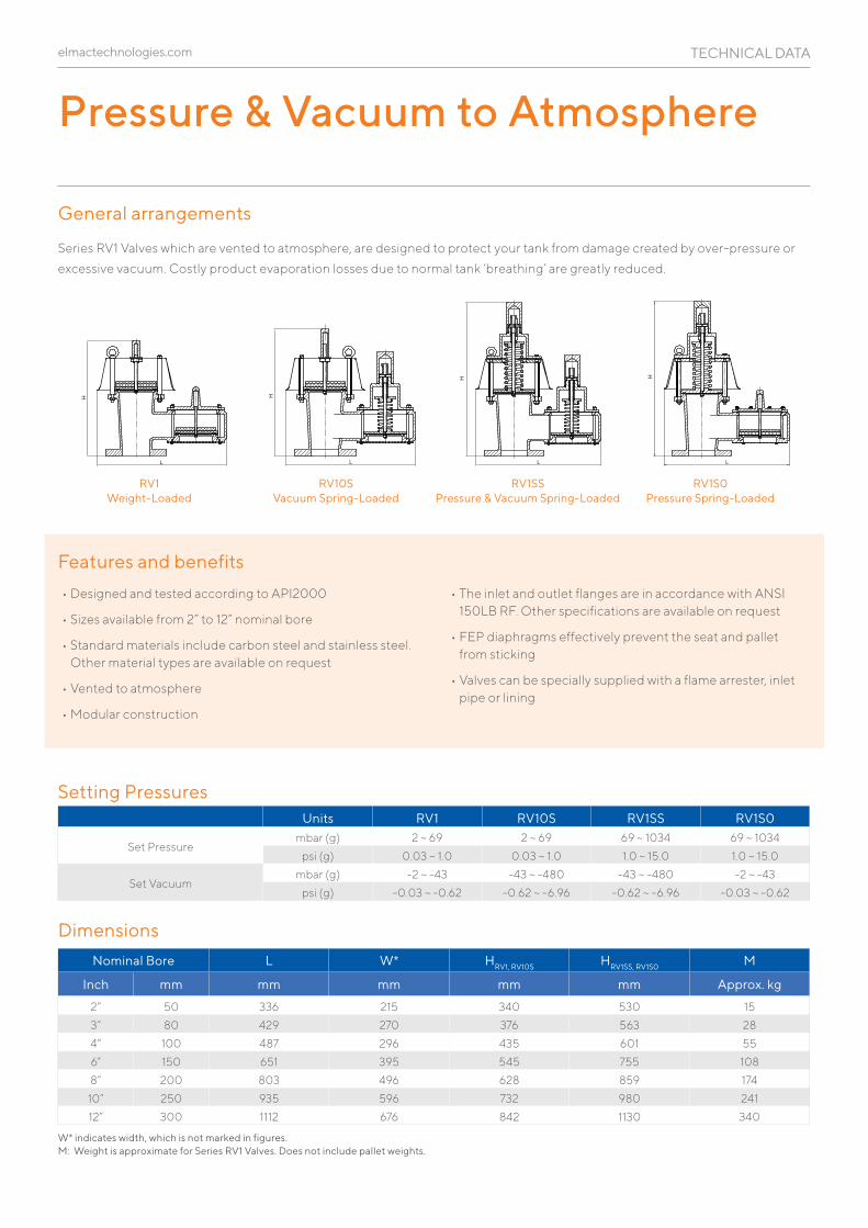
Pressure & Vacuum to Atmosphere
General arrangements
Series RV1 Valves which are vented to atmosphere, are designed to protect your tank from damage created by over-pressure or
excessive vacuum. Costly product evaporation losses due to normal tank ‘breathing’ are greatly reduced.
Nominal Bore L W* HRV1, RV10S HRV1SS, RV1S0 M
Inch mm mm mm mm mm Approx. kg
2” 50 336 215 340 530 15
3” 80 429 270 376 563 28
4” 100 487 296 435 601 55
6” 150 651 395 545 755 108
8” 200 803 496 628 859 174
10” 250 935 596 732 980 241
12” 300 1112 676 842 1130 340L
H
L
H
AL
H
AL
H
L
H
H
LL
A
B
H
AL
B
H
A L
BH
LA
BH
LA
BH
A L
B
H
L
H
L
H
HL L
H
RV1S0 Pressure Spring-Loaded
RV1SS Pressure & Vacuum Spring-Loaded
RV10S Vacuum Spring-Loaded
RV1 Weight-Loaded
Features and benefits
• Designed and tested according to API2000
• Sizes available from 2” to 12” nominal bore
• Standard materials include carbon steel and stainless steel. Other material types are available on request
• Vented to atmosphere
• Modular construction
• The inlet and outlet flanges are in accordance with ANSI 150LB RF. Other specifications are available on request
• FEP diaphragms effectively prevent the seat and pallet from sticking
• Valves can be specially supplied with a flame arrester, inlet pipe or lining
Setting Pressures
Dimensions
W* indicates width, which is not marked in figures. M: Weight is approximate for Series RV1 Valves. Does not include pallet weights.
Units RV1 RV10S RV1SS RV1S0
Set Pressurembar (g) 2 ~ 69 2 ~ 69 69 ~ 1034 69 ~ 1034
psi (g) 0.03 ~ 1.0 0.03 ~ 1.0 1.0 ~ 15.0 1.0 ~ 15.0
Set Vacuummbar (g) -2 ~ -43 -43 ~ -480 -43 ~ -480 -2 ~ -43
psi (g) -0.03 ~ -0.62 -0.62 ~ -6.96 -0.62 ~ -6.96 -0.03 ~ -0.62
TECHNICAL DATA
elmactechnologies.com
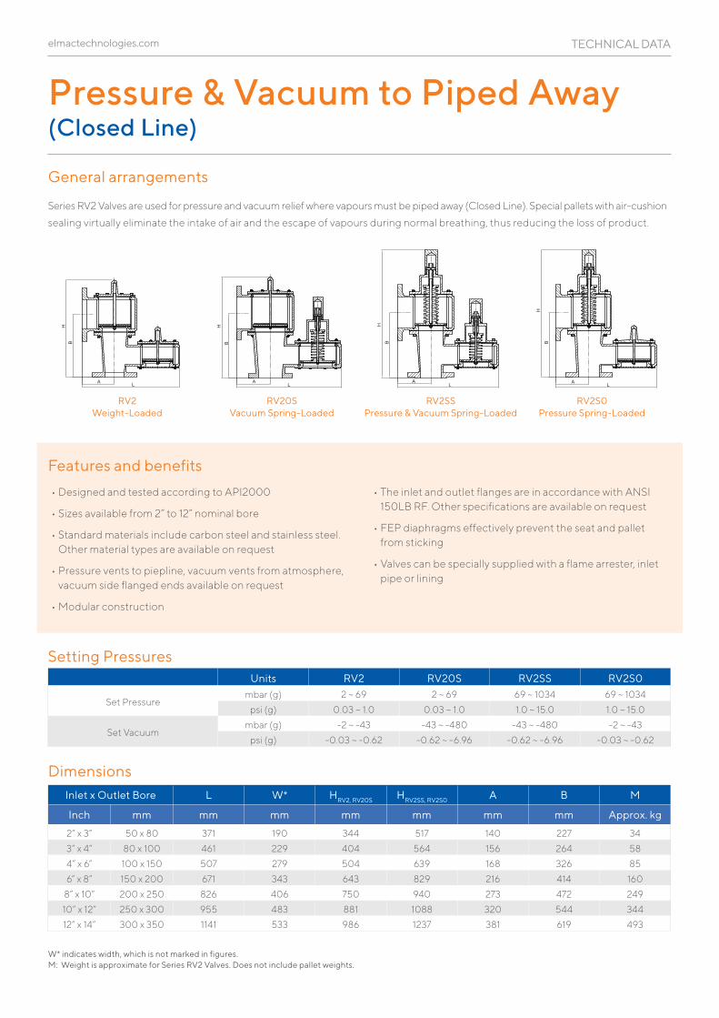
Pressure & Vacuum to Piped Away(Closed Line)
General arrangements
Series RV2 Valves are used for pressure and vacuum relief where vapours must be piped away (Closed Line). Special pallets with air- cushion
sealing virtually eliminate the intake of air and the escape of vapours during normal breathing, thus reducing the loss of product.
RV2S0 Pressure Spring-Loaded
RV2SS Pressure & Vacuum Spring-Loaded
RV20S Vacuum Spring-Loaded
RV2 Weight-Loaded
Features and benefits
• Designed and tested according to API2000
• Sizes available from 2” to 12” nominal bore
• Standard materials include carbon steel and stainless steel. Other material types are available on request
• Pressure vents to piepline, vacuum vents from atmosphere, vacuum side flanged ends available on request
• Modular construction
• The inlet and outlet flanges are in accordance with ANSI 150LB RF. Other specifications are available on request
• FEP diaphragms effectively prevent the seat and pallet from sticking
• Valves can be specially supplied with a flame arrester, inlet pipe or lining
Setting Pressures
Dimensions
W* indicates width, which is not marked in figures. M: Weight is approximate for Series RV2 Valves. Does not include pallet weights.
Units RV2 RV20S RV2SS RV2S0
Set Pressurembar (g) 2 ~ 69 2 ~ 69 69 ~ 1034 69 ~ 1034
psi (g) 0.03 ~ 1.0 0.03 ~ 1.0 1.0 ~ 15.0 1.0 ~ 15.0
Set Vacuummbar (g) -2 ~ -43 -43 ~ -480 -43 ~ -480 -2 ~ -43
psi (g) -0.03 ~ -0.62 -0.62 ~ -6.96 -0.62 ~ -6.96 -0.03 ~ -0.62L
H
L
H
AL
H
AL
H
L
H
H
LL
A
B
H
AL
B
H
A L
BH
LA
BH
LA
BH
A L
B
H
L
H
L
H
H
L L
H
Inlet x Outlet Bore L W* HRV2, RV20S HRV2SS, RV2S0 A B M
Inch mm mm mm mm mm mm mm Approx. kg
2” x 3” 50 x 80 371 190 344 517 140 227 34
3” x 4” 80 x 100 461 229 404 564 156 264 58
4” x 6” 100 x 150 507 279 504 639 168 326 85
6” x 8” 150 x 200 671 343 643 829 216 414 160
8” x 10” 200 x 250 826 406 750 940 273 472 249
10” x 12” 250 x 300 955 483 881 1088 320 544 344
12” x 14” 300 x 350 1141 533 986 1237 381 619 493
TECHNICAL DATA
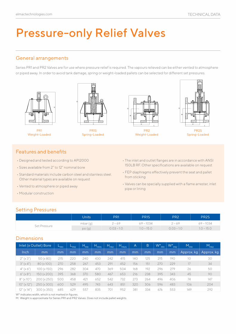
Pressure-only Relief Valves
elmactechnologies.com
Features and benefits
• Designed and tested according to API2000
• Sizes available from 2” to 12” nominal bore
• Standard materials include carbon steel and stainless steel. Other material types are available on request
• Vented to atmosphere or piped away
• Modular construction
• The inlet and outlet flanges are in accordance with ANSI 150LB RF. Other specifications are available on request
• FEP diaphragms effectively prevent the seat and pallet from sticking
• Valves can be specially supplied with a flame arrester, inlet pipe or lining
General arrangements
Series PR1 and PR2 Valves are for use where pressure relief is required. The vapours relieved can be either vented to atmosphere
or piped away. In order to avoid tank damage, spring or weight-loaded pallets can be selected for different set pressures.
Setting Pressures
Dimensions
Units PR1 PR1S PR2 PR2S
Set Pressurembar (g) 2 ~ 69 69 ~ 1034 2 ~ 69 69 ~ 1034
psi (g) 0.03 ~ 1.0 1.0 ~ 15.0 0.03 ~ 1.0 1.0 ~ 15.0
W* indicates width, which is not marked in figures. M: Weight is approximate for Series PR1 and PR2 Valves. Does not include pallet weights.
Inlet (x Outlet) Bore LPR1 LPR2 HPR1 HPR1S HPR2 HPR2S A B W*PR1 W*PR2 MPR1 MPR2
Inch mm mm mm mm mm mm mm mm mm mm mm Approx. kg Approx. kg
2” (x 3”) 50 (x 80) 215 220 240 430 242 415 140 125 215 190 10 30
3” (x 4”) 80 (x 100) 270 258 267 453 291 452 156 151 270 229 17 34
4” (x 6”) 100 (x 150) 296 282 304 470 369 504 168 192 296 279 26 50
6” (x 8”) 150 (x 200) 395 368 370 580 467 653 216 238 395 343 45 90
8” (x 10”) 200 (x 250) 500 458 421 652 542 732 273 264 496 406 74 147
10” (x 12”) 250 (x 300) 600 529 495 743 643 851 320 306 596 483 106 204
12” (x 14”) 300 (x 350) 685 629 557 835 701 952 381 334 676 553 149 292
PR2S Spring-Loaded
PR2 Weight-Loaded
PR1S Spring-Loaded
PR1 Weight-Loaded
L
H
L
H
AL
H
AL
H
L
H
H
LL
A
B
H
AL
B
H
A L
BH
LA
BH
LA
BH
A L
B
H
L
H
L
H
H
L L
H
TECHNICAL DATA
Vacuum-only Relief Valves
Features and benefits
• Designed and tested according to API2000
• Sizes available from 2” to 12” nominal bore for the VR1 Series, or 3” to 14” for the VR2 Series
• Standard materials include carbon steel and stainless steel. Other material types are available on request
• Can be installed on top of the tank with bottom flanged valve, or on the side walls of the tank with side flanged valves
• Modular construction
• The inlet and outlet flanges are in accordance with ANSI 150LB RF. Other specifications are available on request
• FEP diaphragms effectively prevent the seat and pallet from sticking
• Valves can be specially supplied with a flame arrester, inlet pipe or lining
elmactechnologies.com
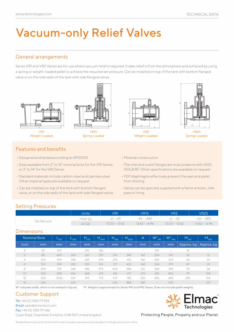
General arrangements
Series VR1 and VR2 Valves are for use where vacuum relief is required. Intake relief is from the atmosphere and achieved by using
a spring or weight-loaded pallet to achieve the required set pressure. Can be installed on top of the tank with bottom flanged
valve or on the side walls of the tank with side flanged valves.
Setting Pressures
Dimensions
W* indicates width, which is not marked in figures. M: Weight is approximate for Series PR1 and PR2 Valves. Does not include pallet weights.
VR2S Spring-Loaded
VR2 Weight-Loaded
VR1S Spring-Loaded
L
H
L
H
AL
H
AL
H
L
H
H
LL
A
B
H
AL
B
H
A L
BH
LA
BH
LA
BH
A L
B
H
L
H
L
H
H
L L
H
VR1 Weight-Loaded
Nominal Bore LVR1 LVR2 HVR1 HVR1S HVR2 HVR2S A W*VR1 W*VR2 MVR1 MVR2
Inch mm mm mm mm mm mm mm mm mm mm Approx. kg Approx. kg
2” 50 307 - 210 383 - - - 158 - 18 -
3” 80 400 220 237 397 212 385 140 204 190 32 12
4” 100 454 258 259 394 255 415 156 228 229 46 20
6” 150 599 282 329 515 317 453 168 304 279 87 35
8” 200 729 368 385 575 400 586 216 368 343 137 68
10” 250 838 456 468 675 481 671 273 418 406 191 105
12” 300 1002 529 519 770 579 786 320 496 483 285 150
14” 350 - 629 - - 634 885 381 - 533 - 210
Units VR1 VR1S VR2 VR2S
Set Vacuummbar (g) -2 ~ -43 -43 ~ -480 -2 ~ -43 -43 ~ -480
psi (g) -0.03 ~ -0.62 -0.62 ~ -6.96 -0.03 ~ -0.62 -0.62 ~ -6.96
TECHNICAL DATA
All specifications are correct at time of print, are for guidance purposes only and subject to change without prior notice.
Tel: +44 (0) 1352 717 555
Email: [email protected]
Fax: +44 (0) 1352 717 642
Coast Road, Greenfield, Flintshire, CH8 9DP United Kingdom
Customer Support
Protecting People, Property and our Planet.