Embed Size (px)
Citation preview

SystemOperating Manual
FUJITSU Workstation CELSIUSW570 / W570power / W570power+W580 / W580power / W580power+
Thank you for buying an innovative product from Fujitsu.
Latest information about our products, useful tips, updates etc. is availableon our website: "http://www.fujitsu.com/fts/"
You can find driver updates at: "http://support.ts.fujitsu.com/download"
Should you have any technical questions, please contact:
• our Hotline/Service Desk ("http://support.ts.fujitsu.com/contact/servicedesk")
• Your sales partner
• Your sales office
We hope you enjoy using your new Fujitsu system!


Published by / Contact address in the EU
Fujitsu Technology Solutions GmbH
Mies-van-der-Rohe-Straße 8
80807 Munich, Germany
"http://www.fujitsu.com/fts/"
Copyright© Fujitsu Technology Solutions GmbH 2.018. All rights reserved.
Publication Date07/2018
Order No.: A26361-K1446-Z320-1-7619, edition 2
FUJITSU Workstation CELSIUSW570 / W570power / W570power+W580 / W580power / W580power+
Operating Manual
Your CELSIUS... 7
Ports and Operating Elements 9
Important notes 11
Getting started 13
Operation 22
Troubleshooting and tips 29
System expansions 33
Technical data 82
Index 83
Remarks
Notes on the product description are consistent with Fujitsu´s design specifications andare made available for comparison purposes. The actual results may differ due to severalfactors. Technical data is subject to change without notification. Fujitsu does not acceptany responsibility for technical or editorial errors nor for omissions.
Trademarks
Fujitsu, the Fujitsu logo and CELSIUS are registered trademarks of Fujitsu Limitedor its subsidiaries in the USA and other countries.
Kensington and MicroSaver are registered trademarks of ACCO Brands.
USB Type-C™ and USB-C™ are trademarks of the USB Implementers Forumin the USA and other countries.
Microsoft and Windows are trademarks or registered trademarks of MicrosoftCorporation in the USA and/or other countries.
All other trademarks mentioned here are the property of their particular owner.
Copyright
No part of this publication may be copied, reproduced or translated withoutprior written permission from Fujitsu.
No part of this publication may be stored or transmitted in any electronic mannerwithout written permission from Fujitsu.

Contents
ContentsYour CELSIUS... . . . . . . . . . . . . . . . . . . . . . . . . . . . . . . . . . . . . . . . . . . . . . . . . . . . . . . . . . . . . . . . . . . . . . . . 7Notational conventions . . . . . . . . . . . . . . . . . . . . . . . . . . . . . . . . . . . . . . . . . . . . . . . . . . . . . . . . . . . . . . . . . . 8Validity of the Reference Manual . . . . . . . . . . . . . . . . . . . . . . . . . . . . . . . . . . . . . . . . . . . . . . . . . . . . . . . . . 8
Ports and Operating Elements . . . . . . . . . . . . . . . . . . . . . . . . . . . . . . . . . . . . . . . . . . . . . . . . . . . . . . . . . 9Front . . . . . . . . . . . . . . . . . . . . . . . . . . . . . . . . . . . . . . . . . . . . . . . . . . . . . . . . . . . . . . . . . . . . . . . . . . . . . . . . . . . 9Rear . . . . . . . . . . . . . . . . . . . . . . . . . . . . . . . . . . . . . . . . . . . . . . . . . . . . . . . . . . . . . . . . . . . . . . . . . . . . . . . . . . . 10
Important notes . . . . . . . . . . . . . . . . . . . . . . . . . . . . . . . . . . . . . . . . . . . . . . . . . . . . . . . . . . . . . . . . . . . . . . . . 11Safety information . . . . . . . . . . . . . . . . . . . . . . . . . . . . . . . . . . . . . . . . . . . . . . . . . . . . . . . . . . . . . . . . . . . . . . . 11Transporting the device . . . . . . . . . . . . . . . . . . . . . . . . . . . . . . . . . . . . . . . . . . . . . . . . . . . . . . . . . . . . . . . . . . 11Cleaning the device . . . . . . . . . . . . . . . . . . . . . . . . . . . . . . . . . . . . . . . . . . . . . . . . . . . . . . . . . . . . . . . . . . . . . 12Energy saving, disposal and recycling . . . . . . . . . . . . . . . . . . . . . . . . . . . . . . . . . . . . . . . . . . . . . . . . . . . . 12
Getting started . . . . . . . . . . . . . . . . . . . . . . . . . . . . . . . . . . . . . . . . . . . . . . . . . . . . . . . . . . . . . . . . . . . . . . . . . 13Unpacking and checking the delivery . . . . . . . . . . . . . . . . . . . . . . . . . . . . . . . . . . . . . . . . . . . . . . . . . . . . . 13Steps for initial setup . . . . . . . . . . . . . . . . . . . . . . . . . . . . . . . . . . . . . . . . . . . . . . . . . . . . . . . . . . . . . . . . . . . . 13Setting up the device . . . . . . . . . . . . . . . . . . . . . . . . . . . . . . . . . . . . . . . . . . . . . . . . . . . . . . . . . . . . . . . . . . . . 14Connecting the device to the mains supply . . . . . . . . . . . . . . . . . . . . . . . . . . . . . . . . . . . . . . . . . . . . . . . . 15Connecting external devices . . . . . . . . . . . . . . . . . . . . . . . . . . . . . . . . . . . . . . . . . . . . . . . . . . . . . . . . . . . . . 16
Ports on the device . . . . . . . . . . . . . . . . . . . . . . . . . . . . . . . . . . . . . . . . . . . . . . . . . . . . . . . . . . . . . . . . . . 17Connecting a monitor . . . . . . . . . . . . . . . . . . . . . . . . . . . . . . . . . . . . . . . . . . . . . . . . . . . . . . . . . . . . . . . . 18Connecting the mouse . . . . . . . . . . . . . . . . . . . . . . . . . . . . . . . . . . . . . . . . . . . . . . . . . . . . . . . . . . . . . . . 19Connecting the keyboard . . . . . . . . . . . . . . . . . . . . . . . . . . . . . . . . . . . . . . . . . . . . . . . . . . . . . . . . . . . . 19Connecting external devices to the parallel or serial interface (optional) . . . . . . . . . . . . . . . . . . 19Connecting external devices to the USB ports . . . . . . . . . . . . . . . . . . . . . . . . . . . . . . . . . . . . . . . . . 20
Switching on for the first time: installing the software . . . . . . . . . . . . . . . . . . . . . . . . . . . . . . . . . . . . . . . 20Switch on the monitor and the machine . . . . . . . . . . . . . . . . . . . . . . . . . . . . . . . . . . . . . . . . . . . . . . . 21Installing the software . . . . . . . . . . . . . . . . . . . . . . . . . . . . . . . . . . . . . . . . . . . . . . . . . . . . . . . . . . . . . . . 21
Operation . . . . . . . . . . . . . . . . . . . . . . . . . . . . . . . . . . . . . . . . . . . . . . . . . . . . . . . . . . . . . . . . . . . . . . . . . . . . . . 22Switch the device on . . . . . . . . . . . . . . . . . . . . . . . . . . . . . . . . . . . . . . . . . . . . . . . . . . . . . . . . . . . . . . . . . . . . 22Switching off the device . . . . . . . . . . . . . . . . . . . . . . . . . . . . . . . . . . . . . . . . . . . . . . . . . . . . . . . . . . . . . . . . . 22
Procedure in an emergency . . . . . . . . . . . . . . . . . . . . . . . . . . . . . . . . . . . . . . . . . . . . . . . . . . . . . . . . . . 22Indicators on the device . . . . . . . . . . . . . . . . . . . . . . . . . . . . . . . . . . . . . . . . . . . . . . . . . . . . . . . . . . . . . . . . . 23Keyboard . . . . . . . . . . . . . . . . . . . . . . . . . . . . . . . . . . . . . . . . . . . . . . . . . . . . . . . . . . . . . . . . . . . . . . . . . . . . . . . 24
Important keys and keyboard shortcuts . . . . . . . . . . . . . . . . . . . . . . . . . . . . . . . . . . . . . . . . . . . . . . . . 24Settings in BIOS Setup . . . . . . . . . . . . . . . . . . . . . . . . . . . . . . . . . . . . . . . . . . . . . . . . . . . . . . . . . . . . . . . . . . 25Property and data protection . . . . . . . . . . . . . . . . . . . . . . . . . . . . . . . . . . . . . . . . . . . . . . . . . . . . . . . . . . . . . 26
Anti-theft protection and lead-sealing . . . . . . . . . . . . . . . . . . . . . . . . . . . . . . . . . . . . . . . . . . . . . . . . . . 26Mechanical casing lock (optional) . . . . . . . . . . . . . . . . . . . . . . . . . . . . . . . . . . . . . . . . . . . . . . . . . . . . . 27BIOS setup security functions . . . . . . . . . . . . . . . . . . . . . . . . . . . . . . . . . . . . . . . . . . . . . . . . . . . . . . . . 28Access authorisation via SmartCard . . . . . . . . . . . . . . . . . . . . . . . . . . . . . . . . . . . . . . . . . . . . . . . . . . 28Operating the SmartCard reader (optional) . . . . . . . . . . . . . . . . . . . . . . . . . . . . . . . . . . . . . . . . . . . . 28
Troubleshooting and tips . . . . . . . . . . . . . . . . . . . . . . . . . . . . . . . . . . . . . . . . . . . . . . . . . . . . . . . . . . . . . . 29Help if problems occur . . . . . . . . . . . . . . . . . . . . . . . . . . . . . . . . . . . . . . . . . . . . . . . . . . . . . . . . . . . . . . . . . . . 29Troubleshooting . . . . . . . . . . . . . . . . . . . . . . . . . . . . . . . . . . . . . . . . . . . . . . . . . . . . . . . . . . . . . . . . . . . . . . . . . 29
Power-on indicator remains unlit after you have switched on your device . . . . . . . . . . . . . . . . . 29The device cannot be switched off with the On/Off switch. . . . . . . . . . . . . . . . . . . . . . . . . . . . . . . 30Monitor remains blank . . . . . . . . . . . . . . . . . . . . . . . . . . . . . . . . . . . . . . . . . . . . . . . . . . . . . . . . . . . . . . . 30No mouse pointer displayed on the screen . . . . . . . . . . . . . . . . . . . . . . . . . . . . . . . . . . . . . . . . . . . . 31
Fujitsu 3
Contents
Time and/or date is not correct . . . . . . . . . . . . . . . . . . . . . . . . . . . . . . . . . . . . . . . . . . . . . . . . . . . . . . . 31Error messages on the screen . . . . . . . . . . . . . . . . . . . . . . . . . . . . . . . . . . . . . . . . . . . . . . . . . . . . . . . . 31
Installing new software . . . . . . . . . . . . . . . . . . . . . . . . . . . . . . . . . . . . . . . . . . . . . . . . . . . . . . . . . . . . . . . . . . 31Tips . . . . . . . . . . . . . . . . . . . . . . . . . . . . . . . . . . . . . . . . . . . . . . . . . . . . . . . . . . . . . . . . . . . . . . . . . . . . . . . . . . . . 32
System expansions . . . . . . . . . . . . . . . . . . . . . . . . . . . . . . . . . . . . . . . . . . . . . . . . . . . . . . . . . . . . . . . . . . . . 33Information about boards . . . . . . . . . . . . . . . . . . . . . . . . . . . . . . . . . . . . . . . . . . . . . . . . . . . . . . . . . . . . . . . . 34Opening the casing . . . . . . . . . . . . . . . . . . . . . . . . . . . . . . . . . . . . . . . . . . . . . . . . . . . . . . . . . . . . . . . . . . . . . 35Closing the casing . . . . . . . . . . . . . . . . . . . . . . . . . . . . . . . . . . . . . . . . . . . . . . . . . . . . . . . . . . . . . . . . . . . . . . 36Open and close the drive cage (only for the model FUJITSU Workstation CELSIUS W570power+/ W580 power+) . . . . . . . . . . . . . . . . . . . . . . . . . . . . . . . . . . . . . . . . . . . . . . . . . . . . . . . . . . . . . . . . . . . . . . . . . 37
Open the drive cage . . . . . . . . . . . . . . . . . . . . . . . . . . . . . . . . . . . . . . . . . . . . . . . . . . . . . . . . . . . . . . . . . 38Pull the drive cage out of the casing. . . . . . . . . . . . . . . . . . . . . . . . . . . . . . . . . . . . . . . . . . . . . . . . . . . 39Slide the drive cage into the housing. . . . . . . . . . . . . . . . . . . . . . . . . . . . . . . . . . . . . . . . . . . . . . . . . . 40Close the drive cage . . . . . . . . . . . . . . . . . . . . . . . . . . . . . . . . . . . . . . . . . . . . . . . . . . . . . . . . . . . . . . . . . 41
Overview of the drive bays and drives in your device . . . . . . . . . . . . . . . . . . . . . . . . . . . . . . . . . . . . . . . 42Install and remove the slim-line drive . . . . . . . . . . . . . . . . . . . . . . . . . . . . . . . . . . . . . . . . . . . . . . . . . . . . . 42
Installing an accessible drive . . . . . . . . . . . . . . . . . . . . . . . . . . . . . . . . . . . . . . . . . . . . . . . . . . . . . . . . . 42Removing an accessible drive . . . . . . . . . . . . . . . . . . . . . . . . . . . . . . . . . . . . . . . . . . . . . . . . . . . . . . . . 43
Installing and removing the accessible 51/4 inch drive . . . . . . . . . . . . . . . . . . . . . . . . . . . . . . . . . . . . . . 45Fitting the drive cover for the 5 1/4 inch drive . . . . . . . . . . . . . . . . . . . . . . . . . . . . . . . . . . . . . . . . . . . 45Installing an accessible drive . . . . . . . . . . . . . . . . . . . . . . . . . . . . . . . . . . . . . . . . . . . . . . . . . . . . . . . . . 46Removing an accessible drive . . . . . . . . . . . . . . . . . . . . . . . . . . . . . . . . . . . . . . . . . . . . . . . . . . . . . . . . 47
Overview of the hard disk drives . . . . . . . . . . . . . . . . . . . . . . . . . . . . . . . . . . . . . . . . . . . . . . . . . . . . . . . . . 48Removing and installing hard disks in the lower part of the device (variants: FUJITSUWorkstation CELSIUS W570 / W570power / W580 / W580power) . . . . . . . . . . . . . . . . . . . . . . . . . . . 53
Removing the hard disk drive . . . . . . . . . . . . . . . . . . . . . . . . . . . . . . . . . . . . . . . . . . . . . . . . . . . . . . . . 54Installing a hard disk drive . . . . . . . . . . . . . . . . . . . . . . . . . . . . . . . . . . . . . . . . . . . . . . . . . . . . . . . . . . . 55
Removing and installing hard disks in the lower part of the device (variant: FUJITSU WorkstationCELSIUS W570power+, cold plug) . . . . . . . . . . . . . . . . . . . . . . . . . . . . . . . . . . . . . . . . . . . . . . . . . . . . . . . 56
Removing the hard disk drive . . . . . . . . . . . . . . . . . . . . . . . . . . . . . . . . . . . . . . . . . . . . . . . . . . . . . . . . 56Installing a hard disk drive . . . . . . . . . . . . . . . . . . . . . . . . . . . . . . . . . . . . . . . . . . . . . . . . . . . . . . . . . . . 58
Removing and installing 21/2 inch hard disks or Solid State Discs (SSD) (FUJITSU WorkstationCELSIUS W570 / W570power and W580 / W580power: according to the operable 51/4 inchdrive, FUJITSU Workstation CELSIUS W570power+ / W580power+: on the drive frame) . . . . . . 59
Removing the hard disk drive (size: 21/2 inches or a Solid State Disc (SSD)) . . . . . . . . . . . . . 60Install a hard disk, size 2 1/2 inches or a Solid State Disk (SSD) . . . . . . . . . . . . . . . . . . . . . . . . . 61
Removing and installing 3 1/2 inch hard disks in the drive cage (only for the model FUJITSUWorkstation CELSIUS W570 power+ with installation kit 1 (standard)) . . . . . . . . . . . . . . . . . . . . . . . 62
Removing the hard disk drive . . . . . . . . . . . . . . . . . . . . . . . . . . . . . . . . . . . . . . . . . . . . . . . . . . . . . . . . 62Installing a hard disk drive . . . . . . . . . . . . . . . . . . . . . . . . . . . . . . . . . . . . . . . . . . . . . . . . . . . . . . . . . . . 63
Removing and installing 2 1/2 inch hard disks in the drive cage (only for the model FUJITSUDesktop CELSIUS W570power+, with both installation kits) . . . . . . . . . . . . . . . . . . . . . . . . . . . . . . . . . 65
Installing the hard disk drive . . . . . . . . . . . . . . . . . . . . . . . . . . . . . . . . . . . . . . . . . . . . . . . . . . . . . . . . . . 65Removing a hard disk drive . . . . . . . . . . . . . . . . . . . . . . . . . . . . . . . . . . . . . . . . . . . . . . . . . . . . . . . . . . 67
Removing and fitting the front fan . . . . . . . . . . . . . . . . . . . . . . . . . . . . . . . . . . . . . . . . . . . . . . . . . . . . . . . . 69Removing the front fan . . . . . . . . . . . . . . . . . . . . . . . . . . . . . . . . . . . . . . . . . . . . . . . . . . . . . . . . . . . . . . 69Installing the front fan . . . . . . . . . . . . . . . . . . . . . . . . . . . . . . . . . . . . . . . . . . . . . . . . . . . . . . . . . . . . . . . . 70
Installing and removing a board . . . . . . . . . . . . . . . . . . . . . . . . . . . . . . . . . . . . . . . . . . . . . . . . . . . . . . . . . . 71Installing a board . . . . . . . . . . . . . . . . . . . . . . . . . . . . . . . . . . . . . . . . . . . . . . . . . . . . . . . . . . . . . . . . . . . . 71Removing a board . . . . . . . . . . . . . . . . . . . . . . . . . . . . . . . . . . . . . . . . . . . . . . . . . . . . . . . . . . . . . . . . . . . 73
Installing and removing an M.2 module . . . . . . . . . . . . . . . . . . . . . . . . . . . . . . . . . . . . . . . . . . . . . . . . . . . 75Installing an M.2 module . . . . . . . . . . . . . . . . . . . . . . . . . . . . . . . . . . . . . . . . . . . . . . . . . . . . . . . . . . . . . 75
4 Fujitsu

Contents
Removing an M.2 module . . . . . . . . . . . . . . . . . . . . . . . . . . . . . . . . . . . . . . . . . . . . . . . . . . . . . . . . . . . . 76Installing and removing WLAN antennas . . . . . . . . . . . . . . . . . . . . . . . . . . . . . . . . . . . . . . . . . . . . . . . . . . 77
Installing external WLAN antennas . . . . . . . . . . . . . . . . . . . . . . . . . . . . . . . . . . . . . . . . . . . . . . . . . . . . 77Removing external WLAN antennas . . . . . . . . . . . . . . . . . . . . . . . . . . . . . . . . . . . . . . . . . . . . . . . . . . 78
Installing and removing heat sinks . . . . . . . . . . . . . . . . . . . . . . . . . . . . . . . . . . . . . . . . . . . . . . . . . . . . . . . . 78Removing the heat sink . . . . . . . . . . . . . . . . . . . . . . . . . . . . . . . . . . . . . . . . . . . . . . . . . . . . . . . . . . . . . . 78Installing the heat sink . . . . . . . . . . . . . . . . . . . . . . . . . . . . . . . . . . . . . . . . . . . . . . . . . . . . . . . . . . . . . . . 79
Mainboard expansions . . . . . . . . . . . . . . . . . . . . . . . . . . . . . . . . . . . . . . . . . . . . . . . . . . . . . . . . . . . . . . . . . . 80Upgrading main memory . . . . . . . . . . . . . . . . . . . . . . . . . . . . . . . . . . . . . . . . . . . . . . . . . . . . . . . . . . . . . 80Replacing the processor . . . . . . . . . . . . . . . . . . . . . . . . . . . . . . . . . . . . . . . . . . . . . . . . . . . . . . . . . . . . . 80Replacing the lithium battery . . . . . . . . . . . . . . . . . . . . . . . . . . . . . . . . . . . . . . . . . . . . . . . . . . . . . . . . . 81
Technical data . . . . . . . . . . . . . . . . . . . . . . . . . . . . . . . . . . . . . . . . . . . . . . . . . . . . . . . . . . . . . . . . . . . . . . . . . 82
Index . . . . . . . . . . . . . . . . . . . . . . . . . . . . . . . . . . . . . . . . . . . . . . . . . . . . . . . . . . . . . . . . . . . . . . . . . . . . . . . . . . 83
Fujitsu 5

Contents
6 Fujitsu
Your CELSIUS...
Your CELSIUS...Overview
... is available with various configuration levels which differ in terms of hardware and softwareequipment. You can install accessible drives (e.g. DVD drives) and other modules.
This manual tells you how to start using your device and how to operate it in daily use.This manual applies for all configuration levels. Depending on the chosen configurationlevel, some of the hardware components described may not be available on your PC.Please also read the notes about your operating system.
Depending on the configuration selected, the operating system is preinstalledon your hard disk (e.g. Windows).
Further information on this device is also provided:
• in the "Quick Start Guide" poster
• in the "Safety/regulations" manual
• in the "Warranty" manual
• in the BIOS manual for your device
• in the operating manual for the monitor
• in the manual for the mainboard
• in the documentation for your operating system
• in the information files (e.g. *.PDF, *.HTML, *.DOC, *.CHM, *.TXT, *.HLP)
Fujitsu 7
Your CELSIUS...
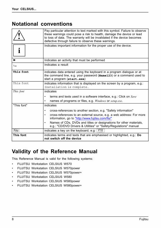
Notational conventionsPay particular attention to text marked with this symbol. Failure to observethese warnings could pose a risk to health, damage the device or leadto loss of data. The warranty will be invalidated if the device becomesdefective through failure to observe these warnings.
Indicates important information for the proper use of the device.
► Indicates an activity that must be performed
Indicates a result
This font indicates data entered using the keyboard in a program dialogue or atthe command line, e.g. your password (Name123) or a command used tostart a program (start.exe)
This font indicates information that is displayed on the screen by a program, e.g.:Installation is complete.
This font indicates
• terms and texts used in a software interface, e.g.: Click on Save
• names of programs or files, e.g. Windows or setup.exe.
"This font" indicates
• cross-references to another section, e.g. "Safety information"
• cross-references to an external source, e.g. a web address: For moreinformation, go to "http://www.fujitsu.com/fts/"
• Names of CDs, DVDs and titles or designations for other materials,e.g.: "CD/DVD Drivers & Utilities" or "Safety/Regulations" manual
Key indicates a key on the keyboard, e.g: F10
This font indicates terms and texts that are emphasised or highlighted, e.g.: Donot switch off the device
Validity of the Reference ManualThis Reference Manual is valid for the following systems:
• FUJITSU Workstation CELSIUS W570
• FUJITSU Workstation CELSIUS W570power
• FUJITSU Workstation CELSIUS W570power+
• FUJITSU Workstation CELSIUS W580
• FUJITSU Workstation CELSIUS W580power
• FUJITSU Workstation CELSIUS W580power+
8 Fujitsu

Ports and Operating Elements
Ports and Operating ElementsPorts
This chapter presents the individual hardware components of your device. This will provideyou with an overview of the ports and operating elements on the device. Please familiariseyourself with these components before you start to work with the device.
Front
23
654
7
18
1 = Slim-line drive
2 = Module bay for a 51/4-inch drive
3 = ON/OFF switch
4 = Slot for memory cards (format: SDSecure Digital card)
5 = USB connection 3.1 with a chargingfunction (USB Type-C™)
6 = USB ports
7 = Microphone connection (right), headphoneconnection (left).In order to use a headset, connect theheadset with both connections.
8 = Latch with optional casing lock
Fujitsu 9

Ports and Operating Elements
Rear
K
4
5
3
12
1 = Device for a Security Lock
2 = Holes for a padlock
3 = Alternating voltage socket (AC IN)
4 = Ports for external devices(device-dependent)
5 = Slot covers
10 Fujitsu
Important notes
Important notesImportantnotesNotes
In this chapter you will find information regarding safety which it is essential totake note of when working with your device.
Safety informationSafetyinformationNote
Please note the information provided in the "Safety/regulations" manualand in the following safety notes.
When installing and operating the device, please observe the notes onenvironmental conditions in Chapter "Technical data", Page 82 as well asthe instructions in Chapter "Getting started", Page 13.
When setting up the device, make sure there is clearance all around it so thatthe casing receives enough ventilation. In order to avoid overheating, do notcover the ventilation areas of the monitor or the device.
You must only operate the device if the rated voltage used by thedevice is set to the local mains voltage.
The main switch (if present) and the ON/OFF switch do not disconnect thedevice from the mains voltage. To completely disconnect from the mainsvoltage, remove the power plug from the power socket.
Only operate the device with the casing closed.
Replace the lithium battery on the mainboard in accordance with the instructionsin "Replacing the lithium battery", Page 81.
Caution, components in the system can get very hot.
The activities described in these instructions must always beperformed with the greatest care.
Repairs to the device must only be performed by qualified technicians.Incorrect repairs could put the user at great risk or cause serious damageto the equipment (electric shock, risk of fire).
Transporting the deviceDevice,TransportationRetransportation
Transport all parts separately in their original packaging or in a packaging whichprotects them from knocks and jolts, to the new site.
Do not unpack them until all transportation manoeuvres are completed.
If the device is brought from a cold environment into the room where it will be used,condensation may occur. Before operating the device, wait until it is absolutely dryand has reached approximately the same temperature as the installation site.
Fujitsu 11

Important notes
Cleaning the deviceDevice,TransportationRetransportationSystemunit,seeDevice
Turn off all power and equipment switches and disconnect the powerplug from the mains outlet.
Do not clean any interior parts yourself, leave this job to a service technician.
Do not use any cleaning agents that contain abrasives or may corrodeplastic (alcohol, thinner or acetone).
Never clean the device with water! Water entering into the device couldpresent a serious risk to users (e.g. electric shock).
Ensure that no liquid enters the system.
The surface can be cleaned with a dry cloth. If particularly dirty, use a cloth that has beenmoistened in mild domestic detergent and then carefully wrung out.
Use disinfectant wipes to clean the keyboard and the mouse.
Energy saving, disposal and recyclingDisposalEnergysavingRecycling
You can find information on these subjects in the "Environment and Energy Information" manualor on our website ("http://www.fujitsu.com/fts/about/fts/environment-care/").
12 Fujitsu

Getting started
Getting startedGettingstarted
Please observe the safety information in the "Important notes", Page 11 chapter.
Unpacking and checking the deliveryIt is recommended not to throw away the original packaging material! It may berequired for reshipment at some later date.PackagingContentsofdeliveryPackaging,
► Unpack all the individual parts.
► Check the contents of the package for any visible damage caused during transport.
► Check whether the delivery conforms to the details in the delivery note.
► Should you discover that the delivery does not correspond to the deliverynote, notify your local sales outlet immediately.
Steps for initial setupPreparingforfirstuse,overviewPreparingforuse,
Only a few steps are necessary to put your new device into operation for the first time:
• Select a location for device and set up device
• Connect external devices such as mouse, keyboard and monitor
• Check the voltage at the mains outlet and connect the device to an electrical outlet
• Switch the device on
You will learn more about the individual steps in the following sections.
External devices
If you have received other external devices in addition to your own device (e.g.a printer), do not connect these until after the initial installation. The followingsections describe how to connect these external devices.
Drives and boards
If you have received drives or boards with your device, please do not installthem until after first-time setup. How to install drives and boards is describedin the "System expansions", Page 33 chapter.
Fujitsu 13

Getting started
Setting up the deviceWorkstationErgonomicDevice
When installing your device, please read the recommendations and safetynotes in the "Safety/regulations" manual.
We recommend that you place your device on a surface which is not slippery. Inview of the many different finishes and varnishes used on furniture, it is possiblethat the rubber feet will mark the surface they stand on.
Depending on the location of your device, bothersome vibrations and noises mayoccur. To prevent this, a distance of at least 10 mm / 0.39 in should be maintainedfrom other devices on casing sides without ventilation surfaces.
In order to avoid overheating, do not cover the ventilation areasof the monitor or the device.
A minimum distance of 200 mm / 7.87 in from the device must beobserved for ventilation areas.
Do not stack several devices on top of each other.
Do not expose the device to extreme ambient conditions (see "Technical data", Page 82,section "Ambient conditions"). Protect the device against dust, humidity and heat.
14 Fujitsu

Getting started
Connecting the device to the mains supplyMainsadapter
Use the following table to check which mains plug applies for your country. Thefollowing illustration may be different from your country variant.
21
► Connect the power cable to the device (1).
► Plug the power plug into a grounded mains outlet (2).
Power connection Country
USA, Canada, Mexico, parts of South America,Japan, Korea, the Philippines, Taiwan
Russia and the Commonwealth of IndependentStates (CIS), large parts of Europe, parts ofSouth America, the Middle East, parts of Africa,Hong Kong, India, large parts of South Asia.
UK, Ireland, Malaysia, Singapore, parts of Africa
China, Australia, New Zealand
Fujitsu 15

Getting started
Connecting external devicesRead the documentation on the external device before connecting it.
With the exception of USB devices, always remove all power plugsbefore connecting external devices!
Do not connect or disconnect cables during a thunderstorm.
Always take hold of the actual plug when disconnecting a cable. Never pull the cable!
To ensure that your device works properly, use only the supplied connectioncable or only use a high-quality connection cable.
16 Fujitsu
Getting started
Ports on the devicePortsExternaldevicesDevice
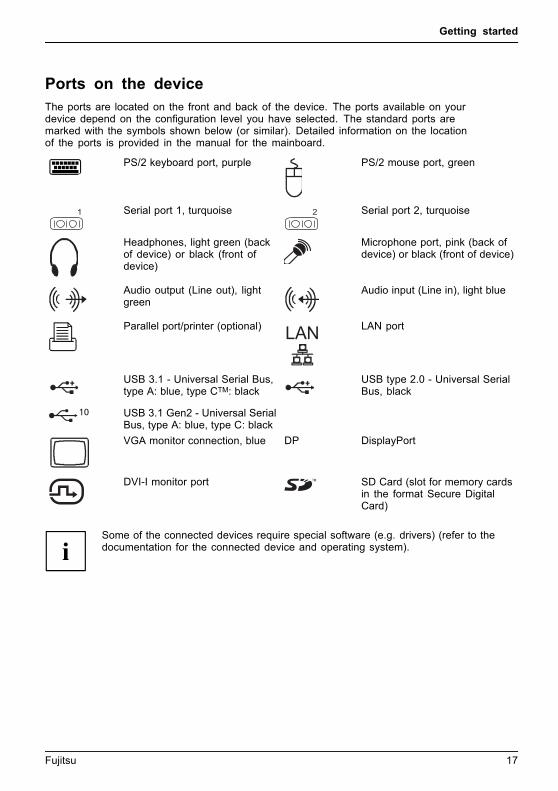
The ports are located on the front and back of the device. The ports available on yourdevice depend on the configuration level you have selected. The standard ports aremarked with the symbols shown below (or similar). Detailed information on the locationof the ports is provided in the manual for the mainboard.
PS/2 keyboard port, purpleKeyboardport
PS/2 mouse port, greenMouseportPS/2mouseport
1 Serial port 1, turquoiseSerialport
2 Serial port 2, turquoiseSerialport
Headphones, light green (backof device) or black (front ofdevice)Headphones
Microphone port, pink (back ofdevice) or black (front of device)Microphonejack
Audio output (Line out), lightgreenAudiooutputLineout
Audio input (Line in), light blueAudioinputLinein
Parallel port/printer (optional)ParallelportPrinter LAN LAN port
LANport
USB 3.1 - Universal Serial Bus,type A: blue, type CTM: blackUniversalSerialBus
USB type 2.0 - Universal SerialBus, black
USB 3.1 Gen2 - Universal SerialBus, type A: blue, type C: black
VGA monitor connection, blueMonitorport
DP DisplayPort
DVI-I monitor port SD Card (slot for memory cardsin the format Secure DigitalCard)
Some of the connected devices require special software (e.g. drivers) (refer to thedocumentation for the connected device and operating system).
Fujitsu 17

Getting started
Connecting a monitorOnly connect the screen to your device when it is switched off.
Depending on requirements, you can use the monitor ports of the mainboard (1) or the monitor portsof an optional display adapter in one of the board slots (2) to connect a monitor to your device.
K
1
2
► Follow the instructions contained in the monitor manual to prepare the monitorfor operation (e.g. connecting cables).
► Connect the data cable to a suitable monitor port of the device (VGA, DVI-I, DisplayPort).
1
► Depending on the connector and configuration level of your device, plug themonitor power cable into an earthed mains outlet (1).
18 Fujitsu
Getting started
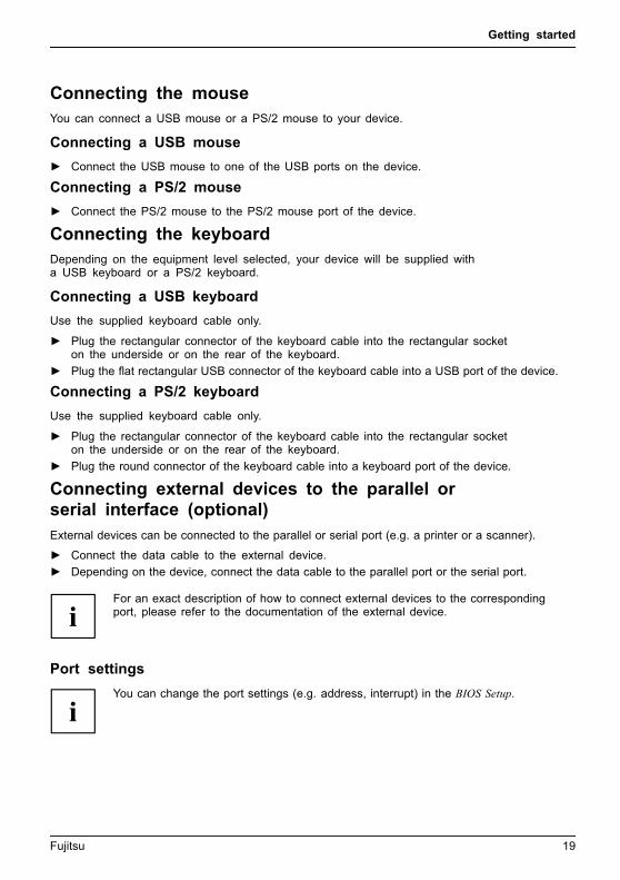
Connecting the mouseYou can connect a USB mouse or a PS/2 mouse to your device.Mouse,Connecting,
Connecting a USB mouse
► Connect the USB mouse to one of the USB ports on the device.USBport,USBport
Connecting a PS/2 mouse
► Connect the PS/2 mouse to the PS/2 mouse port of the device.PS/2mouse,Connecting,PS/2mouse,
Connecting the keyboardDepending on the equipment level selected, your device will be supplied witha USB keyboard or a PS/2 keyboard.Keyboard,Connecting,
Connecting a USB keyboard
Use the supplied keyboard cable only.USBport,Connecting,
► Plug the rectangular connector of the keyboard cable into the rectangular socketon the underside or on the rear of the keyboard.
► Plug the flat rectangular USB connector of the keyboard cable into a USB port of the device.USBport
Connecting a PS/2 keyboard
Use the supplied keyboard cable only.ConnectingaPS/2keyboardConnecting,
► Plug the rectangular connector of the keyboard cable into the rectangular socketon the underside or on the rear of the keyboard.
► Plug the round connector of the keyboard cable into a keyboard port of the device.Keyboard,
Connecting external devices to the parallel orserial interface (optional)ParallelportSerialportParallelportSerialportExternaldevicesDevices
External devices can be connected to the parallel or serial port (e.g. a printer or a scanner).
► Connect the data cable to the external device.
► Depending on the device, connect the data cable to the parallel port or the serial port.
For an exact description of how to connect external devices to the correspondingport, please refer to the documentation of the external device.
Port settingsParallelportSerialport,
You can change the port settings (e.g. address, interrupt) in the BIOS Setup.
Fujitsu 19

Getting started
Device driversDevicedriversDevicedrivers,
The devices connected to the parallel or serial port require drivers. Your operatingsystem already includes many drivers. If the required drive is missing, install it. Currentdrivers are usually available on the Internet or will be supplied on a data carrier.
Connecting external devices to the USB portsUSBdevices,USBport,Externaldevices,Devices,
You can connect a wide range of external devices to the USB ports (e.g.printer, scanner, mouse or keyboard).
USB devices are hot-pluggable. This means you can connect and disconnectUSB cables while your device is switched on.
Additional information can be found in the documentation for the USB devices.
► Connect the data cable to the external device.
► Connect the data cable to one of the USB ports on your device.
Device drivers
External USB devices which you connect to one of the USB ports don’t usuallyneed their own drivers because the software required is already included inthe operating system. If the device requires separate software, please followthe instructions in the manufacturer’s documentation.
Switching on for the first time: installing the softwareInstalling,Software,Installing,
Once the installation has been started the device must not be switchedoff, unless the installation has been completed.
During installation, the device may only be rebooted when you are requested to do so!
The installation will otherwise not be carried out correctly and the contentsof the hard disk must be completely restored.
If the device is integrated into a network, the user and server details as well asthe network protocol are required during the software installation.
Contact your network administrator if you have any questions about these settings.
When you switch on the device for the first time, the supplied softwareis installed and configured. Plan a reasonable amount of time for this,as this process must not be interrupted.
20 Fujitsu
Getting started
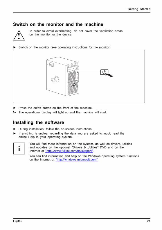
Switch on the monitor and the machineIn order to avoid overheating, do not cover the ventilation areason the monitor or the device.
► Switch on the monitor (see operating instructions for the monitor).
► Press the on/off button on the front of the machine.
The operational display will light up and the machine will start.
Installing the software► During installation, follow the on-screen instructions.
Software,Installing,
► If anything is unclear regarding the data you are asked to input, read theonline Help in your operating system.
You will find more information on the system, as well as drivers, utilitiesand updates on the optional "Drivers & Utilities" DVD and on theInternet at "http://www.fujitsu.com/fts/support".
You can find information and help on the Windows operating system functionson the Internet at "http://windows.microsoft.com".
Fujitsu 21

Operation
Operation
Switch the device on► If necessary, switch the monitor on (see the operating manual for the monitor).
DeviceMonitor
► Press the ON/OFF switch on the front of the device.
The power indicator glows and the device is started.
Switching off the deviceSwitching the device off does not disconnect it from the mains voltage. To completelydisconnect the mains voltage, remove the power plug from the power socket.
► Shut down the operating system in the proper way.DeviceMonitor
The devices switches to power saving mode automatically and switches off.
Procedure in an emergencyIf the device cannot be switched off, you can force a shutdown byusing the following emergency procedure.
Warning, this could lead to a loss of data!
► Press the ON/OFF switch for at least 4 seconds.
The device will switch off.
When you next restart the device, error messages may be displayeddue to the improper shutdown.
22 Fujitsu
Operation
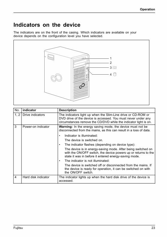
Indicators on the deviceThe indicators are on the front of the casing. Which indicators are available on yourdevice depends on the configuration level you have selected.
1
3
4
2
No. indicator Description
1, 2 Drive indicators The indicators light up when the Slim-Line drive or CD-ROM orDVD drive of the device is accessed. You must never under anycircumstances remove the CD/DVD while the indicator light is on.
3 Power-on indicator Warning: In the energy saving mode, the device must not bedisconnected from the mains, as this can result in a loss of data.
• Indicator is illuminated:
The device is switched on.
• The indicator flashes (depending on device type):
The device is in energy-saving mode. After being switched onwith the ON/OFF switch, the device powers up or returns to thestate it was in before it entered energy-saving mode.
• The indicator is not illuminated:
The device is switched off or disconnected from the mains. Ifthe device is ready for operation, it can be switched on withthe ON/OFF switch.
4 Hard disk indicator The indicator lights up when the hard disk drive of the device isaccessed.
Fujitsu 23
Operation
KeyboardKeyboardKeyboard,Keyboard,Keyboard,Keyboard,Keyboard,AlphanumerickeypadCursorkeysKeys,FunctionkeysNumerickeypadNumerickeypad
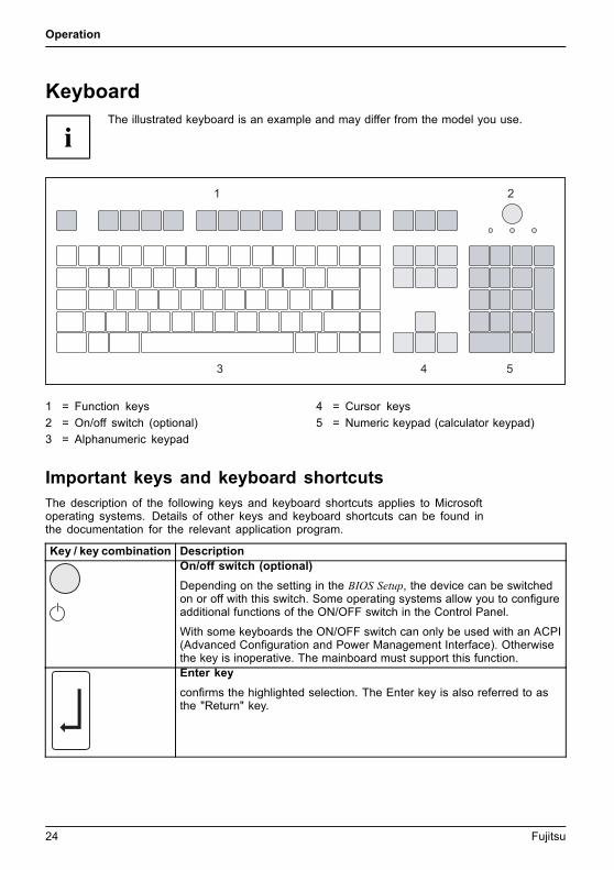
The illustrated keyboard is an example and may differ from the model you use.
1 2
3 4 5
1 = Function keys
2 = On/off switch (optional)
3 = Alphanumeric keypad
4 = Cursor keys
5 = Numeric keypad (calculator keypad)
Important keys and keyboard shortcutsKeysKeyboardshortcuts
The description of the following keys and keyboard shortcuts applies to Microsoftoperating systems. Details of other keys and keyboard shortcuts can be found inthe documentation for the relevant application program.
Key / key combination DescriptionON/OFFswitchButton,
On/off switch (optional)
Depending on the setting in the BIOS Setup, the device can be switchedon or off with this switch. Some operating systems allow you to configureadditional functions of the ON/OFF switch in the Control Panel.
With some keyboards the ON/OFF switch can only be used with an ACPI(Advanced Configuration and Power Management Interface). Otherwisethe key is inoperative. The mainboard must support this function.Keys,Keys,Keys,
Enter key
confirms the highlighted selection. The Enter key is also referred to asthe "Return" key.
24 Fujitsu
Operation
Key / key combination DescriptionKeys,
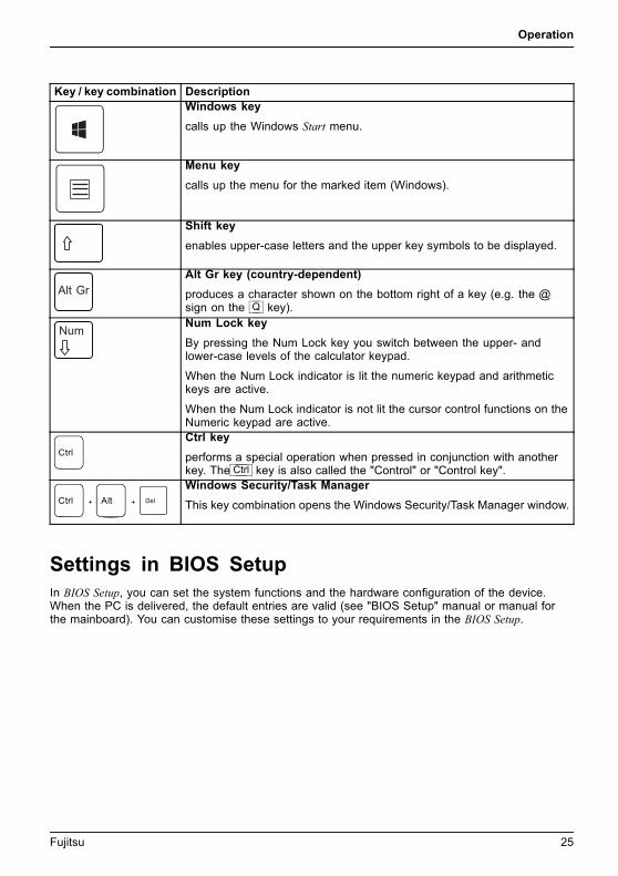
Windows key
calls up the Windows Start menu.
Keys,
Menu key
calls up the menu for the marked item (Windows).
Keys,Keys,
Shift key
enables upper-case letters and the upper key symbols to be displayed.Keys,
Alt Gr key (country-dependent)
produces a character shown on the bottom right of a key (e.g. the @sign on the Q key).Keys,
Num Lock key
By pressing the Num Lock key you switch between the upper- andlower-case levels of the calculator keypad.
When the Num Lock indicator is lit the numeric keypad and arithmetickeys are active.
When the Num Lock indicator is not lit the cursor control functions on theNumeric keypad are active.
Ctrl
Keys,KeysKeysKeys,
Ctrl key
performs a special operation when pressed in conjunction with anotherkey. The Ctrl key is also called the "Control" or "Control key".
AltCtrl Del+ +
Ctrl+Alt+DelCtrl+Alt+DelKeyskeyboardshortcuts
Windows Security/Task Manager
This key combination opens the Windows Security/Task Manager window.
Settings in BIOS SetupBIOSSetup,Systemsettings,BIOSSetup,BIOSSetup,BIOSSetupSetup,
In BIOS Setup, you can set the system functions and the hardware configuration of the device.When the PC is delivered, the default entries are valid (see "BIOS Setup" manual or manual forthe mainboard). You can customise these settings to your requirements in the BIOS Setup.
Fujitsu 25

Operation
Property and data protectionPropertyprotectionDataprotectionSecuritymeasures
Software functions and mechanical locking offer a broad range of functions for protecting your deviceand your personal data against theft and unauthorised access. You can also combine these functions.
Anti-theft protection and lead-sealingDevice,Device,Casing,Lead-sealingAnti-theftprotectionKensingtonLockChain
K
K
1
1 = Holes for a padlock
K
K
2
2 = Device for a security lock
26 Fujitsu
Operation
Anti-theft protection
You can protect your device from theft
• with the holes (1) and a padlock and chain which you have connected to a fixed object beforehand.
• with the Security Lock device (2) and a Kensington MicroSaver. Pleaseconsult the manual for your Security Lock.
Lead-sealing
To prevent unauthorised persons from opening the casing, the casing can be lead-sealed. To dothis, feed the sealing chain through the holes (1) and seal the chain with the lead seal.
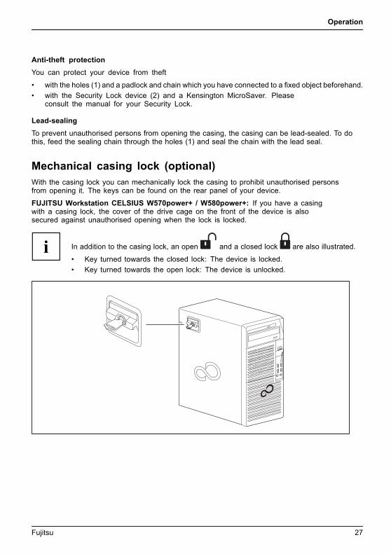
Mechanical casing lock (optional)Casingmechanical lockCasingLockCasing lock
With the casing lock you can mechanically lock the casing to prohibit unauthorised personsfrom opening it. The keys can be found on the rear panel of your device.
FUJITSU Workstation CELSIUS W570power+ / W580power+: If you have a casingwith a casing lock, the cover of the drive cage on the front of the device is alsosecured against unauthorised opening when the lock is locked.
In addition to the casing lock, an open and a closed lock are also illustrated.
• Key turned towards the closed lock: The device is locked.
• Key turned towards the open lock: The device is unlocked.
Fujitsu 27

Operation
Locking the casing
► Turn the key towards the closed lock .
Unlocking the casing
► Turn the key towards the open lock .
BIOS setup security functionsSecurityfunctionsBIOSSetup
The Security menu in BIOS Setup offers you various options for protecting yourpersonal data against unauthorized access, e.g.:
• Prevent unauthorized access to BIOS Setup
• Prevent unauthorised system access
• Prevent unauthorised access to the settings of boards with their own BIOS
• Activate virus warnings
• Protect BIOS from overwriting
• Protect the device from being switched on by an external device
You can also combine these functions.
You will find a detailed description of the Security menus and how to assign passwordsin the manual for the mainboard or in the "BIOS Setup" manual.
Access authorisation via SmartCardSecurityfunctionsAccesspermission,SmartCard
In systems equipped with a SmartCard reader, access can be restricted to thoseusers who have a corresponding SmartCard.
Operating the SmartCard reader (optional)Operation of a SmartCard reader with a RFID reader is not permitted in Taiwan.
► Connect the external SmartCard reader to your system as described inthe instructions for the SmartCard reader.SmartCard reader,
After the device is switched on, you will be prompted to insert your SmartCard.
28 Fujitsu
Troubleshooting and tips
Troubleshooting and tipsRefer to the safety notes in the "Safety/regulations" manual and in the "Gettingstarted", Page 13 chapter when connecting or disconnecting cables.
If a fault occurs, try to correct it as described in the following documentation:
• in this chapter
• in the documentation for the connected devices
• in the help systems of the software used
• in the documentation for your operating system
Help if problems occurShould you encounter a problem with your computer that you cannot resolve yourself:
► Note the ID number of your device. The ID number is found on the type ratingplate on the back, the underside or the top of the casing.
► Contact the Service Desk responsible for your country for clarification of the problem:"http://support.ts.fujitsu.com/contact/servicedesk". When you do this, please haveready the ID number and serial number of your system.
Troubleshooting
Power-on indicator remains unlit after you haveswitched on your deviceCause Troubleshooting
The mains voltage supply is faulty. ► Check whether the power cable is pluggedproperly into the device and a groundedmains outlet.
Internal power supply overloaded. ► Pull the power plug of the device out of themains outlet.
► Wait approx. 3 min.
► Plug the power plug into a properly groundedmains outlet again.
► Switch the device on.
Fujitsu 29
Troubleshooting and tips
The device cannot be switched off with the On/Off switch.Cause Troubleshooting
System crash ► Press the On/Off switch for at least4 seconds, until the device switches off.
Attention: Warning, this could lead to a loss ofdata!
The Operating System is not shut-down properlyin the process. Error messages are thereforepossible the next time the system is booted.
Monitor remains blankCause Remedy
Monitor is switched off ► Switch your monitor on.
Power saving has been activated (screen isblank)
► Press any key on the keyboard.
or► Deactivate the screen saver. If
necessary, enter the appropriatepassword.
Brightness control is set to dark ► Adjust the brightness control. For detailedinformation, please refer to the operatingmanual supplied with your monitor.
Power cable not connected ► Switch off the monitor and the device.
► Check that the monitor power cable isproperly connected to the monitor and toa grounded mains outlet or to the monitorsocket of the device.
► Check that the device power cable isproperly plugged into the device and agrounded mains outlet.
► Switch on the monitor and the device.
Monitor cable not connected ► Switch off the monitor and the device.
► Check that the monitor cable is properlyconnected to the device and monitor.
► Switch on the monitor and the device.
Incorrect setting for the monitor ► Restart the system.
► Press F8 while the system is booting.
► Start the system in Safe Mode.
► Set up the monitor as described in thedocumentation for your operating systemand monitor.
30 Fujitsu

Troubleshooting and tips
No mouse pointer displayed on the screenCause Remedy
The mouse is not correctly connected. ► Shut down your operating system in theproper manner, for instance using Ctrl +Alt + Del .
► Switch the device off.
► Check that the mouse cable is properlyconnected to the system unit. If you use anadapter or extension lead with the mousecable, check the connections.
► Make sure that only one mouse isconnected.
► Switch the device on.
Disabled USB ports ► In the BIOS Setup, check whether the USBports are Enabled (see the "BIOS Setup"manual or the mainboard manual
Time and/or date is not correctCause Remedy
Time and date are incorrect. ► Set the correct time and date within theoperating system you are using.
or► Set the correct time and/or date in the
BIOS Setup.
The lithium battery is discharged. ► If the time and date are repeatedly wrongwhen you switch on your device, replace thelithium battery (see "Replacing the lithiumbattery", Page 81).
Error messages on the screenError messages and their explanations are provided:
• in the technical manual for the mainboard
• in the documentation for the programs used
Installing new softwareWhen installing programs or drivers, important files may be overwritten and modified. Tobe able to access the original data in the event of any problems following installation,you should backup your hard disk prior to installation.
Fujitsu 31
Troubleshooting and tips
TipsTopic Tip
Out of system resources ► Close unnecessary applications.
or► Run the applications in a different order.
32 Fujitsu

System expansions
System expansionsUpgrades,Device,SystemexpansionComponentsServicing
Repairs to the device must only be performed by qualified technicians. Incorrect repairsmay greatly endanger the user (electric shock, fire risk) and will invalidate your warranty.
After consulting the Hotline/Service Desk, you may remove and install thecomponents described in this manual yourself.
As the device has to be shut down in order to install/deinstall system hardwarecomponents, it is a good idea to print out the relevant sections of this chapter beforehand.
The following illustrations may differ slightly from your device, depending on its configuration level.
Nachfolgend ist in der Regel die FUJITSU Workstation CELSIUS W570power+ /W580power+ abgebildet. Auf Unterschiede zwischen den drei Gerätevarianten FUJITSUWorkstation CELSIUS W570 / W580, FUJITSU Workstation CELSIUS W570power /W580power und FUJITSU Workstation CELSIUS W570power+ / W580power+ wirdin den entsprechenden Abschnitten hingewiesen.
If further documentation was delivered with your device, please also read this through carefully.
In addition, before removing or installing system components, please pay attention to the following:
The device must be switched off when installing/removing the systemexpansions and may not be in energy-saving mode.
Remove the power plug before opening the device.
Be careful that no wires become trapped when removing or installing components.
When installing components that become very hot, make sure that the maximumpermissible temperature of the components in operation is not exceeded.
An update of the BIOS may be required for a system expansion or hardwareupgrade. Further information can be found in the BIOS help section or ifnecessary in the Technical Manual for the mainboard.
Fujitsu 33
System expansions
Information about boardsTake care with the locking mechanisms (catches and centring pins) when youare replacing boards or components on boards.
Note that some components on the mainboard may be very hot if the device wasin use shortly before the casing was removed.
To prevent damage to the board or the components and conductors on it, please take care whenyou insert or remove boards. Make sure expansion boards are inserted straightly.
Never use sharp objects (screwdrivers) for leverage.
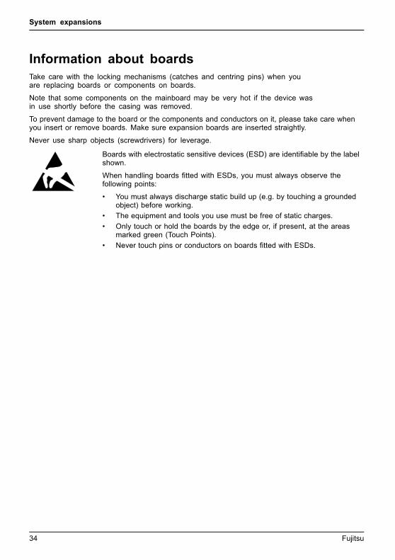
Boards with electrostatic sensitive devices (ESD) are identifiable by the labelshown.
When handling boards fitted with ESDs, you must always observe thefollowing points:
• You must always discharge static build up (e.g. by touching a groundedobject) before working.
• The equipment and tools you use must be free of static charges.
• Only touch or hold the boards by the edge or, if present, at the areasmarked green (Touch Points).
• Never touch pins or conductors on boards fitted with ESDs.
34 Fujitsu
System expansions
Opening the casingCasing,Device,
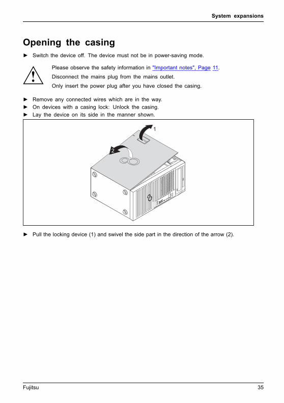
► Switch the device off. The device must not be in power-saving mode.
Please observe the safety information in "Important notes", Page 11.
Disconnect the mains plug from the mains outlet.
Only insert the power plug after you have closed the casing.
► Remove any connected wires which are in the way.
► On devices with a casing lock: Unlock the casing.
► Lay the device on its side in the manner shown.
1
2
► Pull the locking device (1) and swivel the side part in the direction of the arrow (2).
Fujitsu 35

System expansions
Closing the casing► Insert the side part in the guide rail on the lower part of the casing.
Casing,Device,
During the installation, make sure that you insert the detent (a) into the correspondingopening on the housing (b). Otherwise the casing cannot be closed.
1
a
b
► Swivel the side cover in the direction of the arrow (1) until it engages.
► On devices with a casing lock: Lock the casing.
► Reconnect the cables that you disconnected before.
36 Fujitsu

System expansions
Open and close the drive cage (only forthe model FUJITSU Workstation CELSIUSW570power+ / W580 power+)
For some of the work steps described below, the FUJITSU WorkstationCELSIUS W570power+/ W580powert+ requires that the drive cage should beopened and, if necessary, also pulled out of the casing.
Fujitsu 37
System expansions
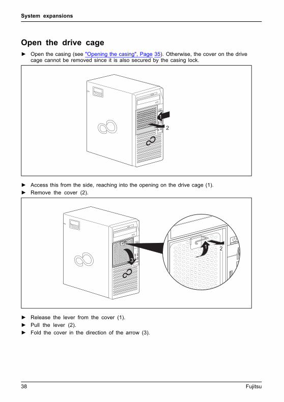
Open the drive cage► Open the casing (see "Opening the casing", Page 35). Otherwise, the cover on the drive
cage cannot be removed since it is also secured by the casing lock.
1
2
► Access this from the side, reaching into the opening on the drive cage (1).
► Remove the cover (2).
21
3
► Release the lever from the cover (1).
► Pull the lever (2).
► Fold the cover in the direction of the arrow (3).
38 Fujitsu

System expansions
Pull the drive cage out of the casing.► Open the drive cage (see "Open the drive cage", Page 38).
2
1
► Fold upwards the lever on the drive cage (1).
► Pull the drive cage out of the casing using the lever (2).
Fujitsu 39

System expansions
Slide the drive cage into the housing.
1
2
► Slide the drive cage into the housing (1).
► Fold the lever on the drive cage back into the cage (2).
► Close the drive cage (see "Close the drive cage", Page 41).
40 Fujitsu

System expansions
Close the drive cage
2
1
► Fold the cover upwards (1).
► Attach the lever to the cover (2).
1
► Position the cover on the drive cage (1).
► Close the casing (see "Closing the casing", Page 36).
Fujitsu 41
System expansions
Overview of the drive bays and drives in your deviceThe casing has space for several accessible and non-accessible drives:
• One installation slot for a slim-line drive
• One installation slot for an accessible 51/4-inch drive
• One installation slot for a M.2 module
• Non-operable hard disk drives, depending on the device variant and the version level /installation kit used ("Overview of the hard disk drives", Page 48)
"Accessible drives" are e.g. DVD or CD ROM drives, into which a data medium can beinserted from outside. "Non-accessible drives" are for example hard disk drives.
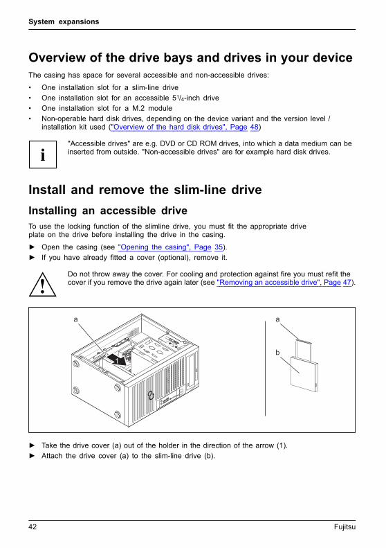
Install and remove the slim-line drive
Installing an accessible driveTo use the locking function of the slimline drive, you must fit the appropriate driveplate on the drive before installing the drive in the casing.
► Open the casing (see "Opening the casing", Page 35).
► If you have already fitted a cover (optional), remove it.
Do not throw away the cover. For cooling and protection against fire you must refit thecover if you remove the drive again later (see "Removing an accessible drive", Page 47).
1
a a
b1
► Take the drive cover (a) out of the holder in the direction of the arrow (1).
► Attach the drive cover (a) to the slim-line drive (b).
42 Fujitsu

System expansions
2
c
► Slide the drive into the housing (2) until it slots into place in the lock (c).
► Close the casing (see "Closing the casing", Page 36).
It may be necessary to modify the entry for the drive in the BIOS Setup.
Removing an accessible drive► Open the casing (see "Opening the casing", Page 35).
1
2
a
3
► Press the release button (1).
► Press the clip (a) in the direction of the arrow (2).
The drive will be pushed forward out of the slot.
► Pull the drive out of the casing in the direction of the arrow (3).
Fujitsu 43

System expansions
b b
c4
► Remove the drive cover (b) from the drive (c).
► Insert the drive cover in the direction of the arrow (4) into the holder.
► If necessary, make the required settings on the remaining hard disk drives.
► If you are not installing a new drive, reinstall the previously removed cover (optional) for thepurposes of cooling, fire protection and to prevent foreign objects from getting into the casing.
► Close the casing (see "Closing the casing", Page 36).
It may be necessary to modify the entry for the drive in the BIOS Setup.
44 Fujitsu
System expansions
Installing and removing the accessible 51/4 inch drive
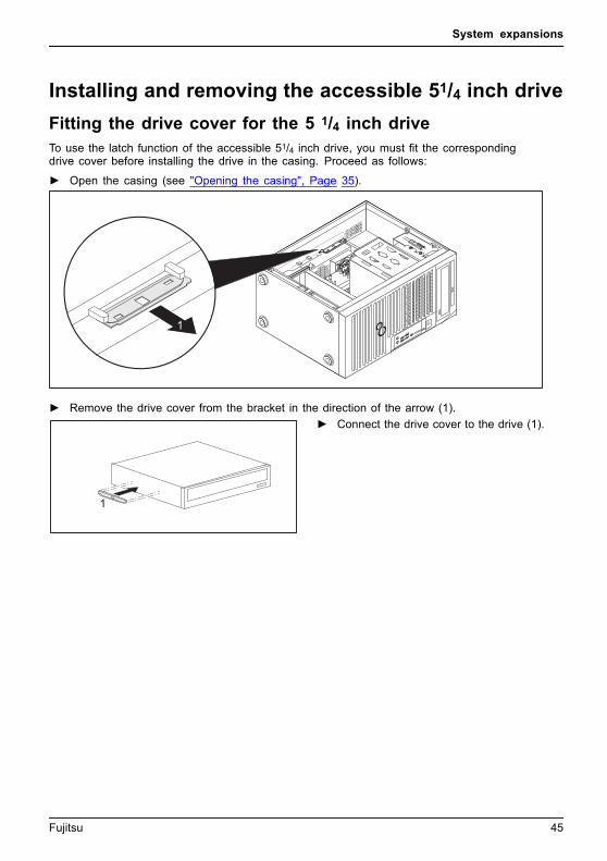
Fitting the drive cover for the 5 1/4 inch driveTo use the latch function of the accessible 51/4 inch drive, you must fit the correspondingdrive cover before installing the drive in the casing. Proceed as follows:
► Open the casing (see "Opening the casing", Page 35).
1
► Remove the drive cover from the bracket in the direction of the arrow (1).
1
► Connect the drive cover to the drive (1).
Fujitsu 45
System expansions
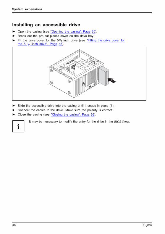
Installing an accessible drive► Open the casing (see "Opening the casing", Page 35).
► Break out the pre-cut plastic cover on the drive bay.
► Fit the drive cover for the 51/4 inch drive (see "Fitting the drive cover forthe 5 1/4 inch drive", Page 45).
1
► Slide the accessible drive into the casing until it snaps in place (1).
► Connect the cables to the drive. Make sure the polarity is correct.
► Close the casing (see "Closing the casing", Page 36).
It may be necessary to modify the entry for the drive in the BIOS Setup.
46 Fujitsu
System expansions
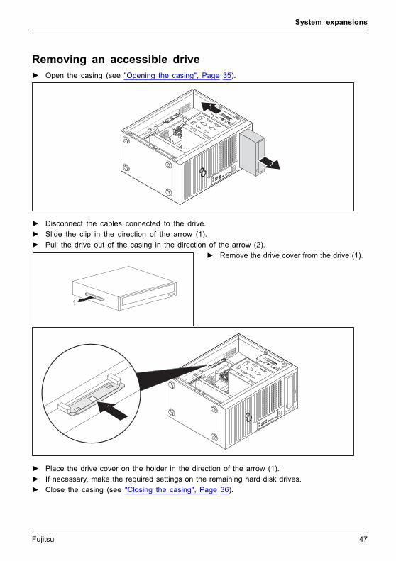
Removing an accessible drive► Open the casing (see "Opening the casing", Page 35).
2
1
► Disconnect the cables connected to the drive.
► Slide the clip in the direction of the arrow (1).
► Pull the drive out of the casing in the direction of the arrow (2).
1
► Remove the drive cover from the drive (1).
1
► Place the drive cover on the holder in the direction of the arrow (1).
► If necessary, make the required settings on the remaining hard disk drives.
► Close the casing (see "Closing the casing", Page 36).
Fujitsu 47

System expansions
It may be necessary to modify the entry for the drive in the BIOS Setup.
Overview of the hard disk drivesThe EasyChange rails for the installation are provided together withthe particular drive or installation kit.
FUJITSU Workstation CELSIUS W570 / W570power / W580 / W580power
2
1
No. Upgrade options Reference
1 One hard disk, size 2 1/2 inches or Solid StateDisk (SSD)
"Removing and installing 21/2 inch harddisks or Solid State Discs (SSD) (FUJITSUWorkstation CELSIUS W570 / W570powerand W580 / W580power: according tothe operable 51/4 inch drive, FUJITSUWorkstation CELSIUS W570power+ /W580power+: on the drive frame)", Page 59
2 hard disks, size 31/2 inches2
2 hard disks, size 21/2 inches
"Removing and installing hard disks in thelower part of the device (variants: FUJITSUWorkstation CELSIUS W570 / W570power /W580 / W580power)", Page 53
48 Fujitsu

System expansions
FUJITSU Workstation CELSIUS W570power+ / W580power+
3
1
2
The FUJITSU Workstation CELSIUS W570power+ / W580power+ is available in twovariants: with the installation kit 1 (standard) or the installation kit 2 (optional). The tablebelow therefore also shows the respective installation options for the two installation kits:
Fujitsu 49
System expansions
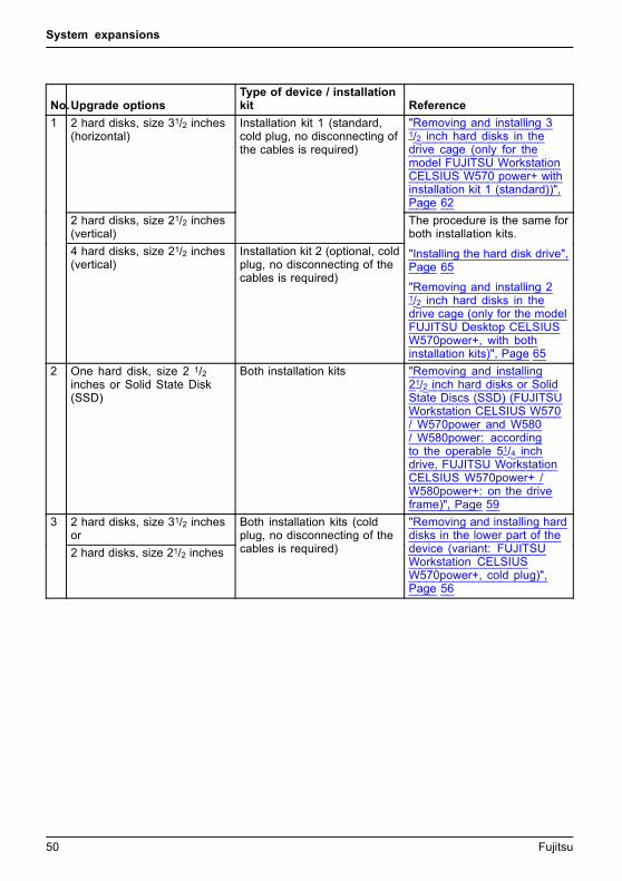
No.Upgrade optionsType of device / installationkit Reference
2 hard disks, size 31/2 inches(horizontal)
"Removing and installing 31/2 inch hard disks in thedrive cage (only for themodel FUJITSU WorkstationCELSIUS W570 power+ withinstallation kit 1 (standard))",Page 62
2 hard disks, size 21/2 inches(vertical)
Installation kit 1 (standard,cold plug, no disconnecting ofthe cables is required)
1
4 hard disks, size 21/2 inches(vertical)
Installation kit 2 (optional, coldplug, no disconnecting of thecables is required)
The procedure is the same forboth installation kits.
"Installing the hard disk drive",Page 65
"Removing and installing 21/2 inch hard disks in thedrive cage (only for the modelFUJITSU Desktop CELSIUSW570power+, with bothinstallation kits)", Page 65
2 One hard disk, size 2 1/2inches or Solid State Disk(SSD)
Both installation kits "Removing and installing21/2 inch hard disks or SolidState Discs (SSD) (FUJITSUWorkstation CELSIUS W570/ W570power and W580/ W580power: accordingto the operable 51/4 inchdrive, FUJITSU WorkstationCELSIUS W570power+ /W580power+: on the driveframe)", Page 59
2 hard disks, size 31/2 inchesor
3
2 hard disks, size 21/2 inches
Both installation kits (coldplug, no disconnecting of thecables is required)
"Removing and installing harddisks in the lower part of thedevice (variant: FUJITSUWorkstation CELSIUSW570power+, cold plug)",Page 56
50 Fujitsu
System expansions
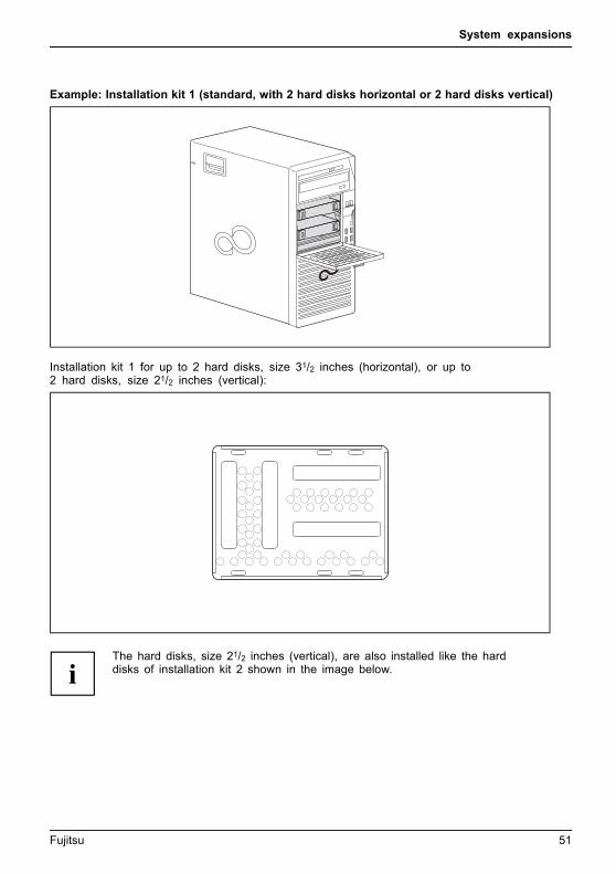
Example: Installation kit 1 (standard, with 2 hard disks horizontal or 2 hard disks vertical)
Installation kit 1 for up to 2 hard disks, size 31/2 inches (horizontal), or up to2 hard disks, size 21/2 inches (vertical):
The hard disks, size 21/2 inches (vertical), are also installed like the harddisks of installation kit 2 shown in the image below.
Fujitsu 51
System expansions
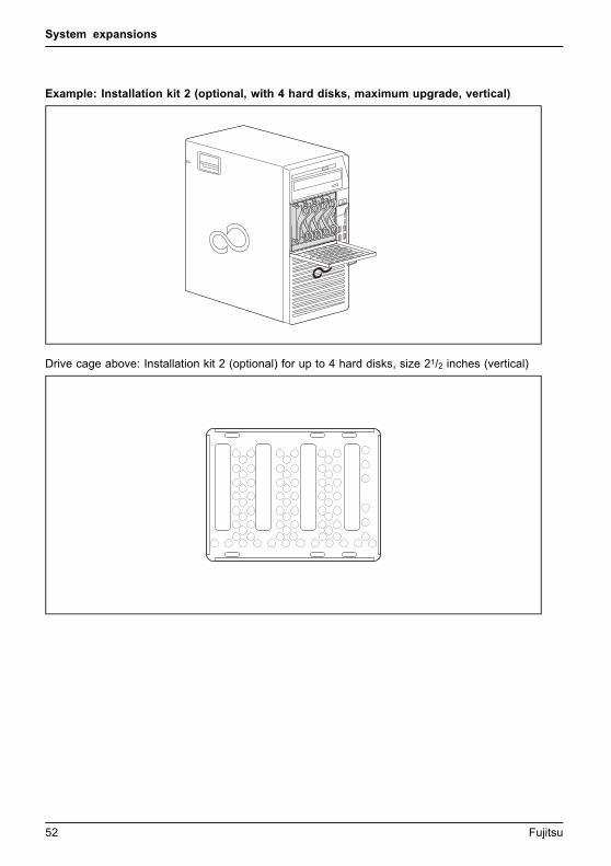
Example: Installation kit 2 (optional, with 4 hard disks, maximum upgrade, vertical)
Drive cage above: Installation kit 2 (optional) for up to 4 hard disks, size 21/2 inches (vertical)
52 Fujitsu
System expansions
Removing and installing hard disks in the lowerpart of the device (variants: FUJITSU WorkstationCELSIUS W570 / W570power / W580 / W580power)
The following sections apply both to 31/2 inch hard disks and to 21/2 inch hard disks.
The only difference between 2 1/2 inch drives and 3 1/2 inch drivesis their EasyChange rails.
Fujitsu 53

System expansions
Removing the hard disk drive► Open the casing (see "Opening the casing", Page 35).
2
1
1
a
a
► Disconnect the cables (a) connected to the hard disk drive.
► Press the brackets of the EasyChange rails on the hard disk drive in the direction of thearrow (1) and pull the hard disk drive out of the drive cage in the direction of the arrow (2).
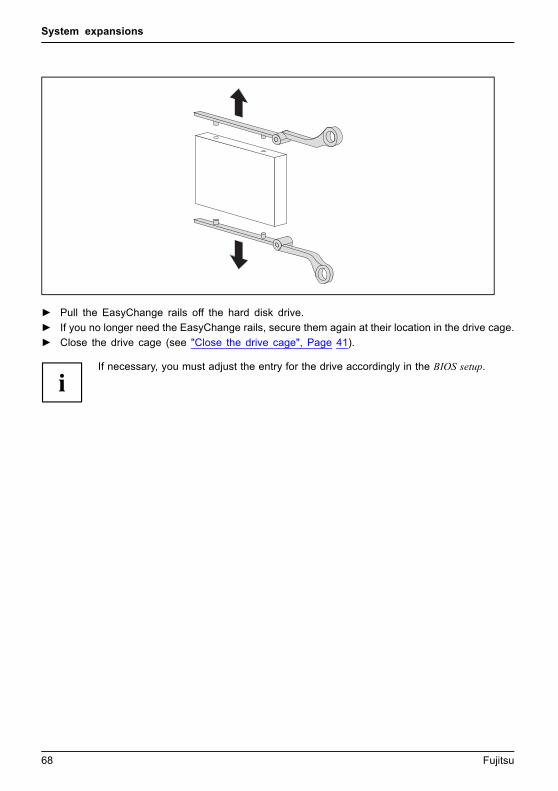
► Pull the EasyChange rails off the hard disk drive.
► If you no longer need the EasyChange rails, secure them again at their location in the drive cage.
It may be necessary to modify the entry for the drive in the BIOS Setup.
54 Fujitsu

System expansions
Installing a hard disk drive► Open the casing (see "Opening the casing", Page 35).
aa
► Secure the EasyChange rails to the side of the hard disk drive by inserting theupper pins of the EasyChange rail into the corresponding holes of the harddisk. The connections (a) face towards the front.
1a
► Slide the hard disk drive with the EasyChange rails into the drive cage in thedirection of the arrow (1). Make sure that the hard disk drive connections (a)are pointing outwards as shown in the diagram.
► Connect the cables to the hard disk drive (a).
► Close the casing (see "Closing the casing", Page 36).
It may be necessary to modify the entry for the drive in the BIOS Setup.
Fujitsu 55
System expansions
Removing and installing hard disks in the lowerpart of the device (variant: FUJITSU WorkstationCELSIUS W570power+, cold plug)
The following sections apply both to 31/2 inch hard disks and to 21/2 inch hard disks.
The only difference between 2 1/2 inch drives and 3 1/2 inch drivesis their EasyChange rails.
Removing the hard disk driveIn the cold-plug process, the cables connected at the back of the drive will bedisconnected automatically when the EasyChange rails are activated, as described below.
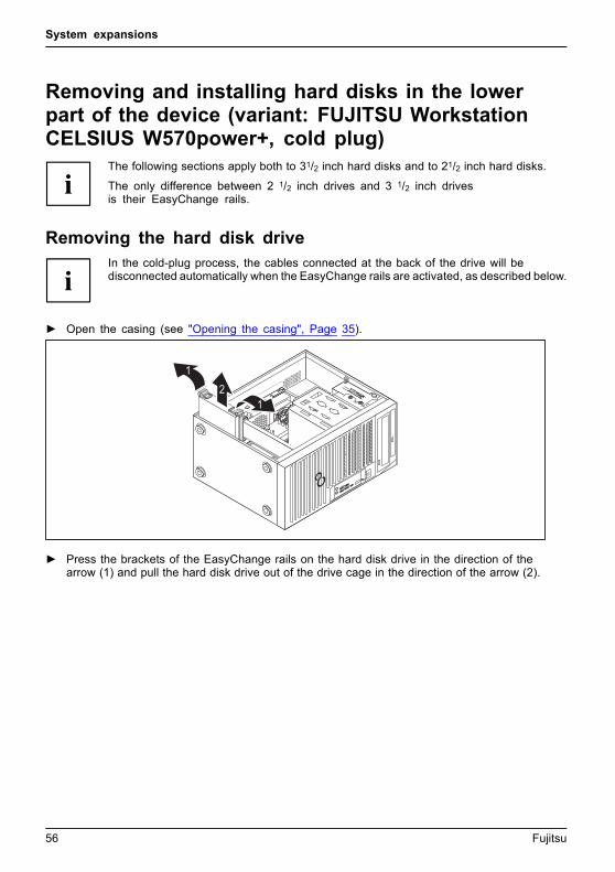
► Open the casing (see "Opening the casing", Page 35).
21
1
► Press the brackets of the EasyChange rails on the hard disk drive in the direction of thearrow (1) and pull the hard disk drive out of the drive cage in the direction of the arrow (2).
56 Fujitsu

System expansions
► Pull the EasyChange rails off the hard disk drive.
► If you no longer need the EasyChange rails, secure them again at their location in the drive cage.
It may be necessary to modify the entry for the drive in the BIOS Setup.
Fujitsu 57

System expansions
Installing a hard disk driveIn the cold-plug process, the cables in the casing for the drive automatically lockinto place when the EasyChange rails are activated, as described below.
► Open the casing (see "Opening the casing", Page 35).
a
► Secure the EasyChange rails to the side of the hard disk drive by inserting theupper pins of the EasyChange rail into the corresponding holes of the harddisk. The connections (a) face towards the rear.
2
12
► Slide the hard disk drive with the EasyChange rails into the drive cage in thedirection of the arrow (1). Ensure that the connections of the hard disk driveface inwards towards the bottom of the casing.
► Press the levers of the EasyChange rails in the direction of the arrows (2).
► Close the casing (see "Closing the casing", Page 36).
58 Fujitsu

System expansions
It may be necessary to modify the entry for the drive in the BIOS Setup.
Removing and installing 21/2 inch hard disks orSolid State Discs (SSD) (FUJITSU WorkstationCELSIUS W570 / W570power and W580 / W580power:according to the operable 51/4 inch drive,FUJITSU Workstation CELSIUS W570power+ /W580power+: on the drive frame)
The procedure is identical for all three device variants and for both installation kits ofthe FUJITSU Workstation CELSIUS W570power+ / W580power+ Only the positionin the casing is different (see "Overview of the hard disk drives", Page 48):
The device variant described below is the FUJITSU WorkstationCELSIUS W570power+. / W580power+
For installation in this model, only use the EasyChange rails designed for thisslot. If no suitable drive has already been installed at the time of delivery,these rails will already be pre-fitted in the slot.
Fujitsu 59
System expansions
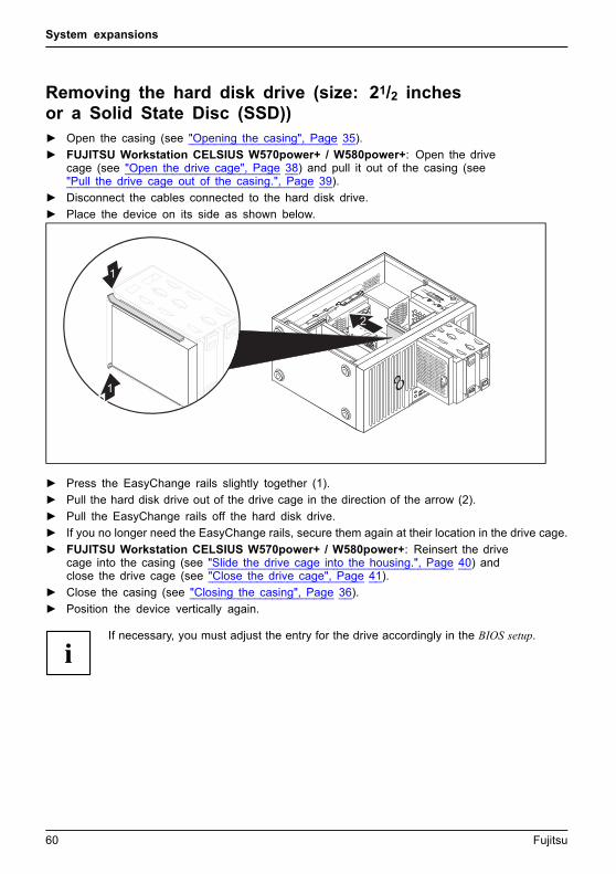
Removing the hard disk drive (size: 21/2 inchesor a Solid State Disc (SSD))► Open the casing (see "Opening the casing", Page 35).
► FUJITSU Workstation CELSIUS W570power+ / W580power+: Open the drivecage (see "Open the drive cage", Page 38) and pull it out of the casing (see"Pull the drive cage out of the casing.", Page 39).
► Disconnect the cables connected to the hard disk drive.
► Place the device on its side as shown below.
1
1
2
► Press the EasyChange rails slightly together (1).
► Pull the hard disk drive out of the drive cage in the direction of the arrow (2).
► Pull the EasyChange rails off the hard disk drive.
► If you no longer need the EasyChange rails, secure them again at their location in the drive cage.
► FUJITSU Workstation CELSIUS W570power+ / W580power+: Reinsert the drivecage into the casing (see "Slide the drive cage into the housing.", Page 40) andclose the drive cage (see "Close the drive cage", Page 41).
► Close the casing (see "Closing the casing", Page 36).
► Position the device vertically again.
If necessary, you must adjust the entry for the drive accordingly in the BIOS setup.
60 Fujitsu

System expansions
Install a hard disk, size 2 1/2 inches or a Solid State Disk (SSD)EasyChange rails for the hard disk drive are located on the drive cage.
► Open the casing (see "Opening the casing", Page 35).
► FUJITSU Workstation CELSIUS W570power+ / W580power+: Open the drivecage (see "Open the drive cage", Page 38) and pull it out of the casing (see"Pull the drive cage out of the casing.", Page 39).
► Place the device on its side as shown below.
1
1
2
► Secure the EasyChange rails on the side of the hard disk (1) by inserting the upper pinsof the EasyChange rail into the corresponding holes of the hard disk.
► Slide the hard disk drive with the EasyChange rails into the drive cage in the directionof the arrow (2), until the hard disk is locked in place.
► Connect the cables to the hard disk drive.
► FUJITSU Workstation CELSIUS W570power+ / W580power+: Reinsert the drivecage into the casing (see "Slide the drive cage into the housing.", Page 40) andclose the drive cage (see "Close the drive cage", Page 41).
► Close the casing (see "Closing the casing", Page 36).
► Position the device vertically again.
If necessary, you must adjust the entry for the drive accordingly in the BIOS setup.
Fujitsu 61

System expansions
Removing and installing 3 1/2 inch hard disksin the drive cage (only for the model FUJITSUWorkstation CELSIUS W570 power+ withinstallation kit 1 (standard))
If you have ordered a device with installation kit 1, you can replace3 1/2 inch hard disks as described below.
21/2 inch hard disks (vertical) are also installed with installation kit 1 (standard)like the hard disks in the following sections with installation kit 2 ("Removing andinstalling 2 1/2 inch hard disks in the drive cage (only for the model FUJITSUDesktop CELSIUS W570power+, with both installation kits)", Page 65).
Removing the hard disk driveIn the cold-plug process, the cables connected at the back of the drive will bedisconnected automatically when the EasyChange rails are activated, as described below.
► Open the drive cage (see "Open the drive cage", Page 38).
21
1
► Press the brackets of the EasyChange rails on the hard disk drive in the direction of thearrow (1) and pull the hard disk drive out of the drive cage in the direction of the arrow (2).
62 Fujitsu
System expansions
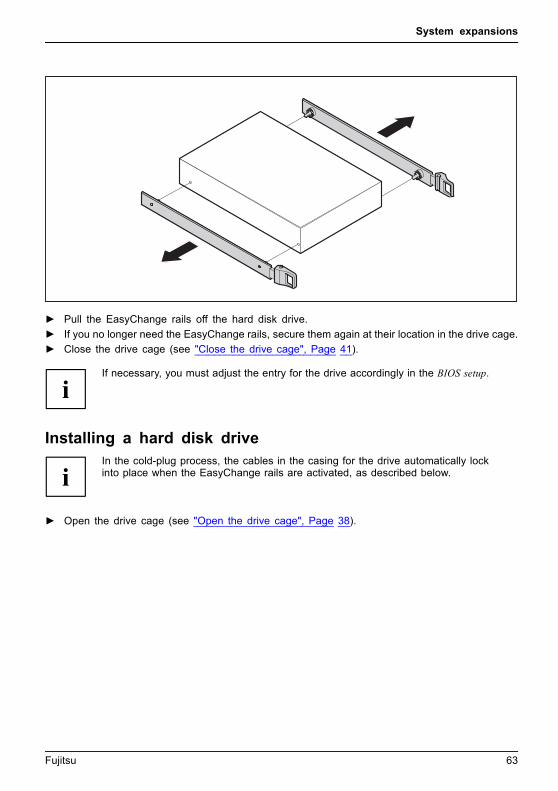
► Pull the EasyChange rails off the hard disk drive.
► If you no longer need the EasyChange rails, secure them again at their location in the drive cage.
► Close the drive cage (see "Close the drive cage", Page 41).
If necessary, you must adjust the entry for the drive accordingly in the BIOS setup.
Installing a hard disk driveIn the cold-plug process, the cables in the casing for the drive automatically lockinto place when the EasyChange rails are activated, as described below.
► Open the drive cage (see "Open the drive cage", Page 38).
Fujitsu 63

System expansions
a
► Secure the EasyChange rails to the side of the hard disk drive by inserting theupper pins of the EasyChange rail into the corresponding holes of the harddisk. The connections (a) face towards the rear.
12
2
► Slide the hard disk drive with the EasyChange rails into the drive cage in thedirection of the arrow (1). Ensure that the connections of the hard disk driveface inwards towards the inside of the casing.
► Press the levers of the EasyChange rails in the direction of the arrow (1).
► Close the drive cage (see "Close the drive cage", Page 41).
If necessary, you must adjust the entry for the drive accordingly in the BIOS setup.
64 Fujitsu
System expansions
Removing and installing 2 1/2 inch hard disks in thedrive cage (only for the model FUJITSU DesktopCELSIUS W570power+, with both installation kits)
The procedure for installation kit 1 (for the installation variant with up to two 2 1/2 inchdrives, vertical) is identical to that of installation kit 2 (up to four 2 1/2 inch drives,vertical)
The device variant with installation kit 2 and four drives is shown below.
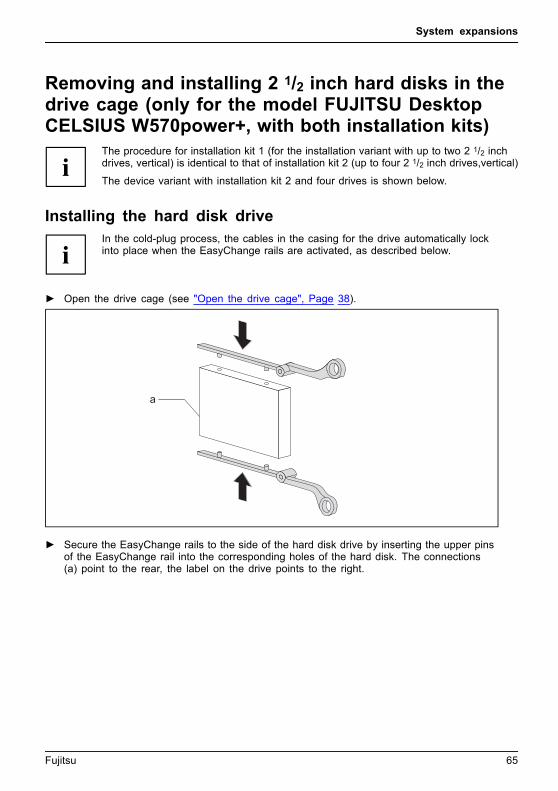
Installing the hard disk driveIn the cold-plug process, the cables in the casing for the drive automatically lockinto place when the EasyChange rails are activated, as described below.
► Open the drive cage (see "Open the drive cage", Page 38).
a
► Secure the EasyChange rails to the side of the hard disk drive by inserting the upper pinsof the EasyChange rail into the corresponding holes of the hard disk. The connections(a) point to the rear, the label on the drive points to the right.
Fujitsu 65

System expansions
1
► Press together the EasyChange rails (1) and push the hard disk drive into the drivecage in the direction of the arrow (2). Ensure that the connections of the hard diskdrive face inwards towards the inside of the casing.
► Close the drive cage (see "Close the drive cage", Page 41).
If necessary, you must adjust the entry for the drive accordingly in the BIOS setup.
66 Fujitsu
System expansions
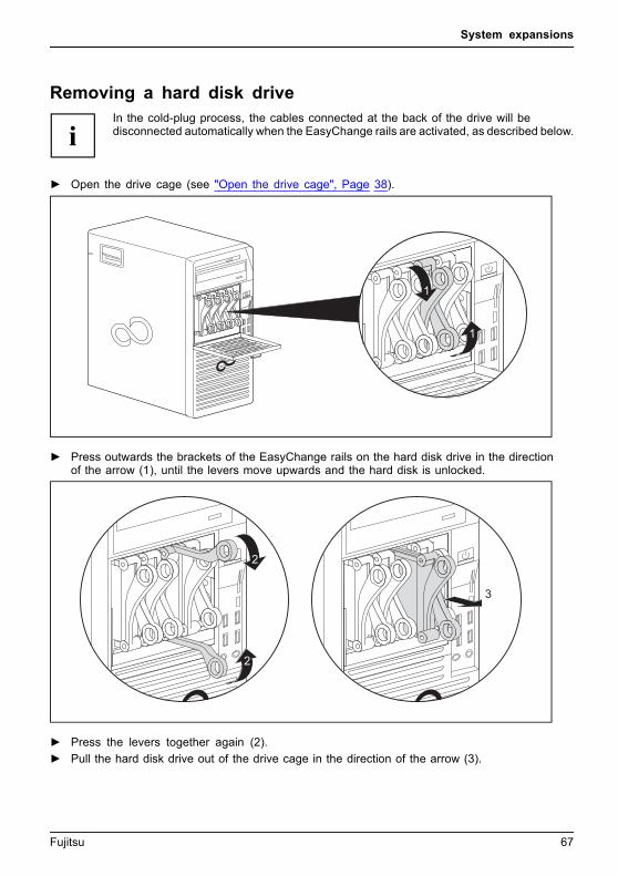
Removing a hard disk driveIn the cold-plug process, the cables connected at the back of the drive will bedisconnected automatically when the EasyChange rails are activated, as described below.
► Open the drive cage (see "Open the drive cage", Page 38).
1
1
► Press outwards the brackets of the EasyChange rails on the hard disk drive in the directionof the arrow (1), until the levers move upwards and the hard disk is unlocked.
2
2
3
► Press the levers together again (2).
► Pull the hard disk drive out of the drive cage in the direction of the arrow (3).
Fujitsu 67
System expansions
► Pull the EasyChange rails off the hard disk drive.
► If you no longer need the EasyChange rails, secure them again at their location in the drive cage.
► Close the drive cage (see "Close the drive cage", Page 41).
If necessary, you must adjust the entry for the drive accordingly in the BIOS setup.
68 Fujitsu
System expansions
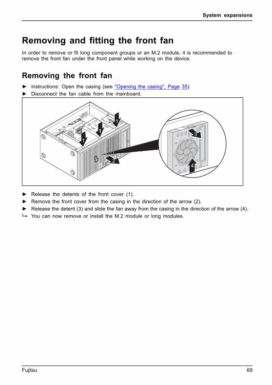
Removing and fitting the front fanIn order to remove or fit long component groups or an M.2 module, it is recommended toremove the front fan under the front panel while working on the device.
Removing the front fan► Instructions: Open the casing (see "Opening the casing", Page 35).
► Disconnect the fan cable from the mainboard.
4
1
2
1
1
1 3
► Release the detents of the front cover (1).
► Remove the front cover from the casing in the direction of the arrow (2).
► Release the detent (3) and slide the fan away from the casing in the direction of the arrow (4).
You can now remove or install the M.2 module or long modules.
Fujitsu 69

System expansions
Installing the front fan
1
2
► Attach the front fan to the centering pins on the housing and move it in the direction of the arrow (1).
The front fan will then be locked in position.
► Fit the front cover onto the casing (2).
► Connect the fan cable to the mainboard.
► Close the casing (see "Closing the casing", Page 36).
70 Fujitsu
System expansions
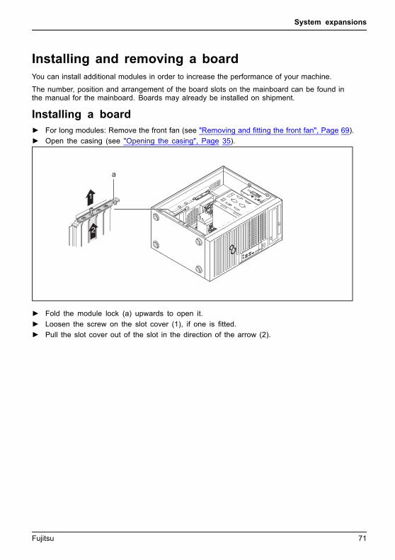
Installing and removing a boardYou can install additional modules in order to increase the performance of your machine.
The number, position and arrangement of the board slots on the mainboard can be found inthe manual for the mainboard. Boards may already be installed on shipment.Board,Board,
Installing a board► For long modules: Remove the front fan (see "Removing and fitting the front fan", Page 69).
► Open the casing (see "Opening the casing", Page 35).Board
2
1
a
► Fold the module lock (a) upwards to open it.
► Loosen the screw on the slot cover (1), if one is fitted.
► Pull the slot cover out of the slot in the direction of the arrow (2).
Fujitsu 71
System expansions
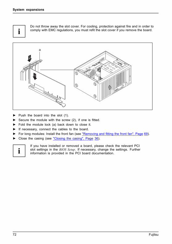
Do not throw away the slot cover. For cooling, protection against fire and in order tocomply with EMC regulations, you must refit the slot cover if you remove the board.
a
1
2
► Push the board into the slot (1).
► Secure the module with the screw (2), if one is fitted.
► Fold the module lock (a) back down to close it.
► If necessary, connect the cables to the board.
► For long modules: Install the front fan (see "Removing and fitting the front fan", Page 69).
► Close the casing (see "Closing the casing", Page 36).
If you have installed or removed a board, please check the relevant PCIslot settings in the BIOS Setup. If necessary, change the settings. Furtherinformation is provided in the PCI board documentation.
72 Fujitsu
System expansions
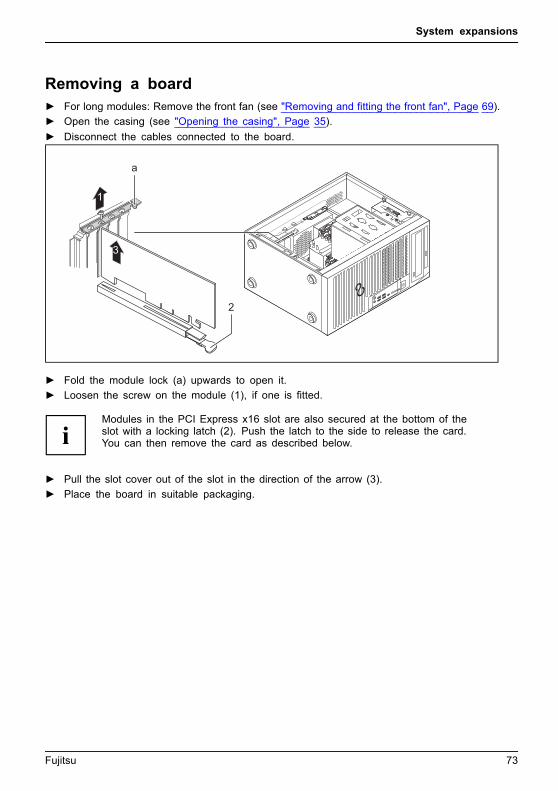
Removing a board► For long modules: Remove the front fan (see "Removing and fitting the front fan", Page 69).
► Open the casing (see "Opening the casing", Page 35).Board
► Disconnect the cables connected to the board.
3
1
2
a
► Fold the module lock (a) upwards to open it.
► Loosen the screw on the module (1), if one is fitted.
Modules in the PCI Express x16 slot are also secured at the bottom of theslot with a locking latch (2). Push the latch to the side to release the card.You can then remove the card as described below.
► Pull the slot cover out of the slot in the direction of the arrow (3).
► Place the board in suitable packaging.
Fujitsu 73
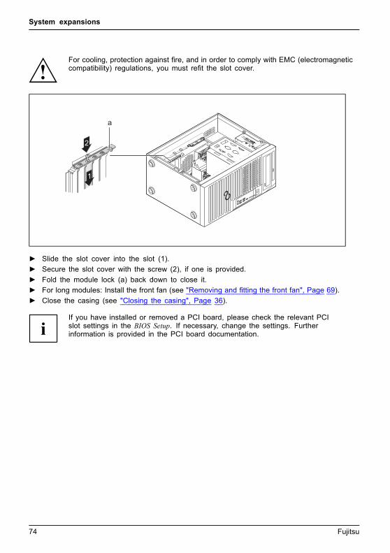
System expansions
For cooling, protection against fire, and in order to comply with EMC (electromagneticcompatibility) regulations, you must refit the slot cover.
1
2
a
► Slide the slot cover into the slot (1).
► Secure the slot cover with the screw (2), if one is provided.
► Fold the module lock (a) back down to close it.
► For long modules: Install the front fan (see "Removing and fitting the front fan", Page 69).
► Close the casing (see "Closing the casing", Page 36).
If you have installed or removed a PCI board, please check the relevant PCIslot settings in the BIOS Setup. If necessary, change the settings. Furtherinformation is provided in the PCI board documentation.
74 Fujitsu
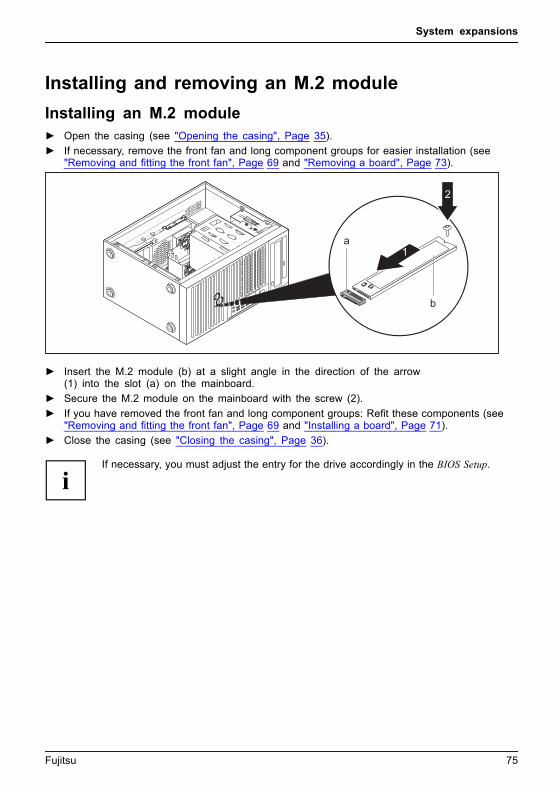
System expansions
Installing and removing an M.2 module
Installing an M.2 module► Open the casing (see "Opening the casing", Page 35).
► If necessary, remove the front fan and long component groups for easier installation (see"Removing and fitting the front fan", Page 69 and "Removing a board", Page 73).
b
a1
2
► Insert the M.2 module (b) at a slight angle in the direction of the arrow(1) into the slot (a) on the mainboard.
► Secure the M.2 module on the mainboard with the screw (2).
► If you have removed the front fan and long component groups: Refit these components (see"Removing and fitting the front fan", Page 69 and "Installing a board", Page 71).
► Close the casing (see "Closing the casing", Page 36).
If necessary, you must adjust the entry for the drive accordingly in the BIOS Setup.
Fujitsu 75
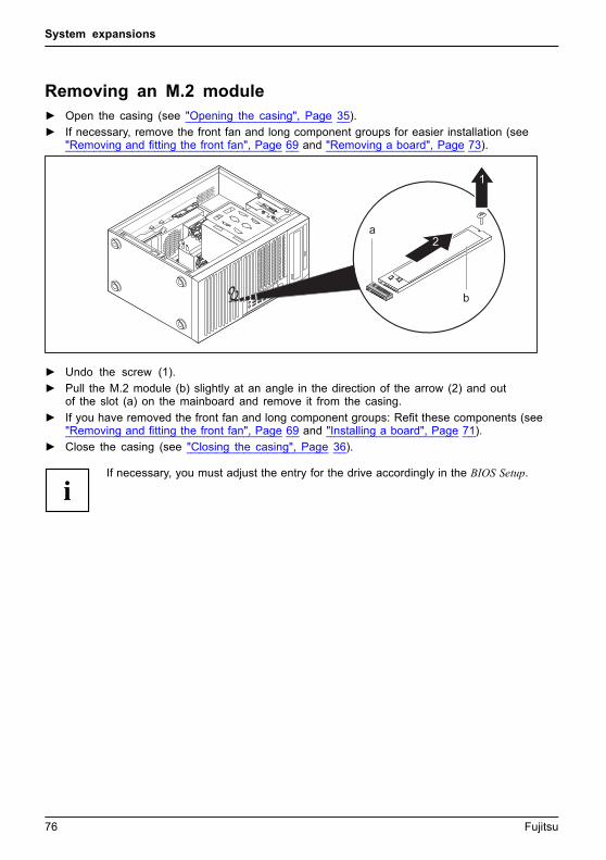
System expansions
Removing an M.2 module► Open the casing (see "Opening the casing", Page 35).
► If necessary, remove the front fan and long component groups for easier installation (see"Removing and fitting the front fan", Page 69 and "Removing a board", Page 73).
b
a2
1
► Undo the screw (1).
► Pull the M.2 module (b) slightly at an angle in the direction of the arrow (2) and outof the slot (a) on the mainboard and remove it from the casing.
► If you have removed the front fan and long component groups: Refit these components (see"Removing and fitting the front fan", Page 69 and "Installing a board", Page 71).
► Close the casing (see "Closing the casing", Page 36).
If necessary, you must adjust the entry for the drive accordingly in the BIOS Setup.
76 Fujitsu

System expansions
Installing and removing WLAN antennasIf you have installed a suitable low-profile board, you can install and remove theassociated WLAN antennas as described below.
Operation of WLAN antennas is not permitted in Taiwan.
Installing external WLAN antennas• A suitable board is installed (see "Installing a board", Page 71).
1
2
3
3
► Working in the direction of the arrow (1), place the WLAN antennas ontothe plug-in positions of the board (2).
► Secure the WLAN antennas by turning in the direction of the arrow (3).
► Align the WLAN antennas as required.
Fujitsu 77

System expansions
Removing external WLAN antennas► Undo the WLAN antennas by turning in the direction of the arrow (1).
► Pull the WLAN antennas in the direction of the arrow (3) and away fromthe plug-in positions of the board (2).
Installing and removing heat sinks
Removing the heat sinkThe shape and position of the heat sink are device-dependent. Theapproach is the same for all variants.
► Open the casing (see "Opening the casing", Page 35).
► FUJITSU Workstation CELSIUS W570+ / W580power+: Open the drive cage(see "Open the drive cage", Page 38) and pull the drive cage out of the casing(see "Pull the drive cage out of the casing.", Page 39).
► Disconnect the fan cable (FAN (CPU)) from the mainboard.
1
a
► Undo the screws on the heat sink (a).
► Lift the heat sink out of the casing (1).
You can now replace the processor (see "Replacing the processor", Page 80).
Never operate the device without a heat sink! Before initial startup, install the heatsink again in the same way as it was installed in the device before removal.
78 Fujitsu
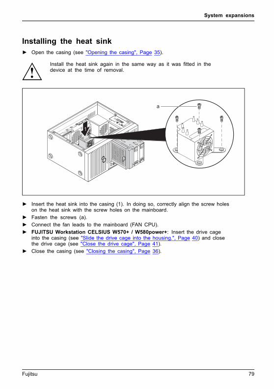
System expansions
Installing the heat sink► Open the casing (see "Opening the casing", Page 35).
Install the heat sink again in the same way as it was fitted in thedevice at the time of removal.
a
1
► Insert the heat sink into the casing (1). In doing so, correctly align the screw holeson the heat sink with the screw holes on the mainboard.
► Fasten the screws (a).
► Connect the fan leads to the mainboard (FAN CPU).
► FUJITSU Workstation CELSIUS W570+ / W580power+: Insert the drive cageinto the casing (see "Slide the drive cage into the housing.", Page 40) and closethe drive cage (see "Close the drive cage", Page 41).
► Close the casing (see "Closing the casing", Page 36).
Fujitsu 79

System expansions
Mainboard expansionsDetails on how to upgrade the main memory or the processor of your devicecan be found in the manual for the mainboard.UpgradesLithiumbatteryProcessorMainmemoryMainboard
Upgrading main memory► Open the casing (see "Opening the casing", Page 35).
Mainmemory
► FUJITSU Workstation CELSIUS W570+ / W580power+: Open the drive cage(see "Open the drive cage", Page 38) and pull the drive cage out of the casing(see "Pull the drive cage out of the casing.", Page 39).
► Upgrade the main memory according to the description in the manual for the mainboard.
► FUJITSU Workstation CELSIUS W570+ / W580power+: Insert the drive cageinto the casing (see "Slide the drive cage into the housing.", Page 40) and closethe drive cage (see "Close the drive cage", Page 41).
► Close the casing (see "Closing the casing", Page 36).
Replacing the processor► Open the casing (see "Opening the casing", Page 35).
► Remove the heat sink (see "Removing the heat sink", Page 78).
► Replace the processor as described in the manual for the mainboard.
► Install the heat sink again (see "Installing the heat sink", Page 79).
► Close the casing (see "Closing the casing", Page 36).
80 Fujitsu
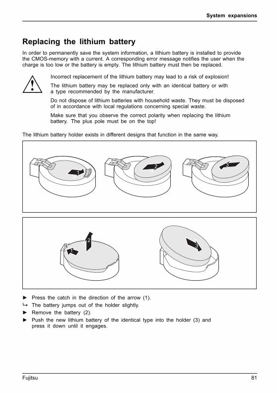
System expansions
Replacing the lithium batteryIn order to permanently save the system information, a lithium battery is installed to providethe CMOS-memory with a current. A corresponding error message notifies the user when thecharge is too low or the battery is empty. The lithium battery must then be replaced.
Incorrect replacement of the lithium battery may lead to a risk of explosion!
The lithium battery may be replaced only with an identical battery or witha type recommended by the manufacturer.
Do not dispose of lithium batteries with household waste. They must be disposedof in accordance with local regulations concerning special waste.
Make sure that you observe the correct polarity when replacing the lithiumbattery. The plus pole must be on the top!Lithiumbattery,Replacing,Replacing,Replacing, lithiumbatteryBattery
The lithium battery holder exists in different designs that function in the same way.
12 3
1
23
► Press the catch in the direction of the arrow (1).
The battery jumps out of the holder slightly.
► Remove the battery (2).
► Push the new lithium battery of the identical type into the holder (3) andpress it down until it engages.
Fujitsu 81

Technical data
Technical dataElectrical data
Protection class: I
Rated voltage range 100 V – 240 V
Rated frequency 50 Hz – 60 Hz
Max. rated current
CELSIUS W570 (250 W)
100 V – 240 V
3.3 – 1.3 A
CELSIUS W570power / W570power+ (360 W) 4.4 – 1.8 A
CELSIUS W580 (250 W) 3.5 – 1.5 A
CELSIUS W580power / W580power+ (360 W) 4.6 – 2.1A
Dimensions
Height/width/depth: 180 mm x 313 mm x 374 mm /
7,09 in x 12,32 in x 14,72 in
Weight
in basic configuration (configuration dependent: about 7.5 kg /
16,5 lbs
Ambient conditions
Environment class 3K2
Environment class 2K2
DIN IEC 721 part 3-3
DIN IEC 721 part 3-2
Temperature
Operation (3K2) 10 °C .... 35 °C / 50 °F ... 95 °F
Transportation (2K2) -25 °C .... 60 °C / -3 °F ... 140 °F
The formation of condensation is not permitted while the device is in operation !
Clearance required to ensure adequate ventilation:
without air vents at least 10 mm /
0,39 in
with air vents at least 200 mm /
7,87 in
The data sheets of these devices contains further technical data. The data sheetscan be found on our website at "http://www.fujitsu.com/fts/".
82 Fujitsu

Index
IndexAAccess permission, SmartCard 28Alphanumeric keypad 24Anti-theft protection 26Audio input 17Audio output 17
BBattery 81BIOS Setup 25
security functions 28BIOS Setup,
configuration 25settings 25system settings 25
Boardinstalling 71removing 73
Board,installing 71removing 71
Button,ON/OFF switch 24
CCasing
Mechanical lock 27Casing lock 27Casing mechanical lock 27Casing,
closing 36Lead-sealing 26opening 35
Chain 26Components
installing/removing 33Connecting a PS/2 keyboard 19Connecting,
keyboard 19mouse 19PS/2 keyboard 19PS/2 mouse 19USB keyboard 19
Contents of delivery 13Ctrl+Alt+Del 25Cursor keys 24
DData protection 26
DeviceConnections 17setting up 14switching off 22Switching on 22
Device driversParallel port 20
Device drivers,Serial port 20
Device,Anti-theft protection 26closing 36Lead-sealing 26opening 35transporting 11–12upgrades 33
Devicesconnecting 19
Devices,connecting 20
Disposal 12
EEnergy saving 12Ergonomic
Workstation 14External devices
connecting 19Ports 17
External devices,connecting 20
FFunction keys 24
GGetting started 13
HHeadphones 17
IImportant notes 11Installing,
software 20–21switching on for the first time 20
Fujitsu 83

Index
KKensington Lock 26Keyboard 24Keyboard port 17keyboard shortcuts 25Keyboard shortcuts 24Keyboard,
alphanumeric keypad 24connecting 19cursor keys 24function keys 24numeric keypad 24port 19
Keys 24Ctrl 25Ctrl+Alt+Del 25
Keys,Alt Gr 25Control 25Ctrl key 25cursor keys 24Enter 24Enter key 24menu key 25Num Lock 25Return 24shift 25shift key 25Start key 25
LLAN port 17Lead-sealing 26Line in 17Line out 17Lithium battery 80Lithium battery,
replacing 81Lock 27
MMain memory 80
upgrading 80Mainboard
Upgrades 80Mains adapter
connecting 15Microphone jack 17Monitor
switching off 22Switching on 22
Monitor port 17
Mouse port 17Mouse,
connecting 19
NNote
safety 11Notes
important 11Numeric keypad 24
OON/OFF switch 24Overview
Device 7
PPackaging 13Packaging,
unpacking 13Parallel port 17, 19
Connecting devices 19Settings 19
Ports 9, 17Preparing for first use, overview 13Preparing for use,
overview 13Printer 17Processor 80Property protection 26PS/2 mouse port 17PS/2 mouse,
connecting 19port 19
RRecycling 12Replacing,
lithium battery 81Replacing, lithium battery 81Retransportation 11–12
SSafety information 11Security functions
BIOS Setup 28SmartCard 28
Security measures 26Serial port 17, 19
Connecting devices 19
84 Fujitsu

Index
Serial port,Settings 19
Servicing 33Setup,
see BIOS Setup 25SmartCard reader,
operating 28Software,
installing 20–21System expansion 33System settings,
BIOS Setup 25System unit, see Device 12
TTransportation 11–12
UUniversal Serial Bus 17
UpgradesMainboard 80
Upgrades,device 33
USB devices,connecting 20
USB port 19USB port,
connecting devices 20connecting keyboard 19connecting the mouse 19
WWorkstation 14
Fujitsu 85