Embed Size (px)
Citation preview

SystemOperating Manual
FUJITSU WorkstationCELSIUS W550 / W550power

Thank you for buying an innovative product from Fujitsu.
Latest information about our products, useful tips, updates etc. is availableon our website: "http://www.fujitsu.com/fts/"
You can find driver updates at: "http://support.ts.fujitsu.com/download"
Should you have any technical questions, please contact:
• our Hotline/Service Desk (see Service Desk list or from the Internet at:"http://support.ts.fujitsu.com/contact/servicedesk")
• Your sales partner• Your sales officeWe hope you enjoy using your new Fujitsu system!


Published by / Contact address in the EU
Fujitsu Technology Solutions GmbH
Mies-van-der-Rohe-Straße 8
80807 Munich, Germany
"http://www.fujitsu.com/fts/"
Copyright© Fujitsu Technology Solutions GmbH 2015. All rights reserved.
Publication Date10/2015
Order No.: A26361-K1445-Z321-1-7619, edition 1

FUJITSU WorkstationCELSIUS W550 / W550power
Operating Manual
Your CELSIUS... 5
Ports and operating elements 7
Important notes 9
Getting started 13
Operation 21
Troubleshooting and tips 28
System expansions 32
Technical data 55
Index 56

RemarksInformation on the product description meets the design specifications of Fujitsu andis provided for comparison purposes. Several factors may cause the actual results todiffer. Technical data is subject to change without prior notification. Fujitsu rejects anyresponsibility with regard to technical or editorial mistakes or omissions.
TrademarksFujitsu, the Fujitsu logo and CELSIUS are registered trademarks of Fujitsu Limitedor its subsidiaries in the USA and other countries.
Kensington is a registered trademark of the ACCO brand.
Microsoft and Windows are trademarks or registered trademarks of MicrosoftCorporation in the USA and/or other countries.
DVI is a registered trademark or unregistered trademark of the Digital Display Working Group.
All other trademarks specified here are the property of their respective owners.
CopyrightNo part of this publication may be copied, reproduced or translated withoutthe prior written consent of Fujitsu.
No part of this publication may be saved or transferred by any electronic meanswithout the written approval of Fujitsu.

Contents
ContentsYour CELSIUS... . . . . . . . . . . . . . . . . . . . . . . . . . . . . . . . . . . . . . . . . . . . . . . . . . . . . . . . . . . . . . . . . . . . . . . . 5Validity of the Reference Manual . . . . . . . . . . . . . . . . . . . . . . . . . . . . . . . . . . . . . . . . . . . . . . . . . . . . . . . . . 5Notational conventions . . . . . . . . . . . . . . . . . . . . . . . . . . . . . . . . . . . . . . . . . . . . . . . . . . . . . . . . . . . . . . . . . . 6
Ports and operating elements . . . . . . . . . . . . . . . . . . . . . . . . . . . . . . . . . . . . . . . . . . . . . . . . . . . . . . . . . 7Front . . . . . . . . . . . . . . . . . . . . . . . . . . . . . . . . . . . . . . . . . . . . . . . . . . . . . . . . . . . . . . . . . . . . . . . . . . . . . . . . . . . 7Rear . . . . . . . . . . . . . . . . . . . . . . . . . . . . . . . . . . . . . . . . . . . . . . . . . . . . . . . . . . . . . . . . . . . . . . . . . . . . . . . . . . . 8
Important notes . . . . . . . . . . . . . . . . . . . . . . . . . . . . . . . . . . . . . . . . . . . . . . . . . . . . . . . . . . . . . . . . . . . . . . . . 9Safety information . . . . . . . . . . . . . . . . . . . . . . . . . . . . . . . . . . . . . . . . . . . . . . . . . . . . . . . . . . . . . . . . . . . . . . . 9Transporting the device . . . . . . . . . . . . . . . . . . . . . . . . . . . . . . . . . . . . . . . . . . . . . . . . . . . . . . . . . . . . . . . . . . 9Cleaning the device . . . . . . . . . . . . . . . . . . . . . . . . . . . . . . . . . . . . . . . . . . . . . . . . . . . . . . . . . . . . . . . . . . . . . 10Energy saving, disposal and recycling . . . . . . . . . . . . . . . . . . . . . . . . . . . . . . . . . . . . . . . . . . . . . . . . . . . . 10CE marking . . . . . . . . . . . . . . . . . . . . . . . . . . . . . . . . . . . . . . . . . . . . . . . . . . . . . . . . . . . . . . . . . . . . . . . . . . . . 11FCC Compliance Statement . . . . . . . . . . . . . . . . . . . . . . . . . . . . . . . . . . . . . . . . . . . . . . . . . . . . . . . . . . . . . 12
FCC Class B Compliance Statement . . . . . . . . . . . . . . . . . . . . . . . . . . . . . . . . . . . . . . . . . . . . . . . . . . 12
Getting started . . . . . . . . . . . . . . . . . . . . . . . . . . . . . . . . . . . . . . . . . . . . . . . . . . . . . . . . . . . . . . . . . . . . . . . . . 13Unpacking and checking the delivery . . . . . . . . . . . . . . . . . . . . . . . . . . . . . . . . . . . . . . . . . . . . . . . . . . . . . 13Steps for initial setup . . . . . . . . . . . . . . . . . . . . . . . . . . . . . . . . . . . . . . . . . . . . . . . . . . . . . . . . . . . . . . . . . . . . 13Setting up the device . . . . . . . . . . . . . . . . . . . . . . . . . . . . . . . . . . . . . . . . . . . . . . . . . . . . . . . . . . . . . . . . . . . . 14Connecting the machine to the mains . . . . . . . . . . . . . . . . . . . . . . . . . . . . . . . . . . . . . . . . . . . . . . . . . . . . . 14Connecting external devices . . . . . . . . . . . . . . . . . . . . . . . . . . . . . . . . . . . . . . . . . . . . . . . . . . . . . . . . . . . . . 15
Ports on the device . . . . . . . . . . . . . . . . . . . . . . . . . . . . . . . . . . . . . . . . . . . . . . . . . . . . . . . . . . . . . . . . . . 15Connecting a monitor . . . . . . . . . . . . . . . . . . . . . . . . . . . . . . . . . . . . . . . . . . . . . . . . . . . . . . . . . . . . . . . . 16Connecting the mouse . . . . . . . . . . . . . . . . . . . . . . . . . . . . . . . . . . . . . . . . . . . . . . . . . . . . . . . . . . . . . . . 17Connecting the keyboard . . . . . . . . . . . . . . . . . . . . . . . . . . . . . . . . . . . . . . . . . . . . . . . . . . . . . . . . . . . . 18Connecting external devices to the parallel (optional) or serial port . . . . . . . . . . . . . . . . . . . . . . 18Connecting external devices to the USB ports . . . . . . . . . . . . . . . . . . . . . . . . . . . . . . . . . . . . . . . . . 19
Switching on for the first time: installing the software . . . . . . . . . . . . . . . . . . . . . . . . . . . . . . . . . . . . . . . 19Switching on monitor and device . . . . . . . . . . . . . . . . . . . . . . . . . . . . . . . . . . . . . . . . . . . . . . . . . . . . . 20Installing the software . . . . . . . . . . . . . . . . . . . . . . . . . . . . . . . . . . . . . . . . . . . . . . . . . . . . . . . . . . . . . . . 20
Operation . . . . . . . . . . . . . . . . . . . . . . . . . . . . . . . . . . . . . . . . . . . . . . . . . . . . . . . . . . . . . . . . . . . . . . . . . . . . . . 21Indicators on the device . . . . . . . . . . . . . . . . . . . . . . . . . . . . . . . . . . . . . . . . . . . . . . . . . . . . . . . . . . . . . . . . . 21Switch the device on . . . . . . . . . . . . . . . . . . . . . . . . . . . . . . . . . . . . . . . . . . . . . . . . . . . . . . . . . . . . . . . . . . . . 21Switching off the device . . . . . . . . . . . . . . . . . . . . . . . . . . . . . . . . . . . . . . . . . . . . . . . . . . . . . . . . . . . . . . . . . 22Keyboard . . . . . . . . . . . . . . . . . . . . . . . . . . . . . . . . . . . . . . . . . . . . . . . . . . . . . . . . . . . . . . . . . . . . . . . . . . . . . . . 23
Important keys and keyboard shortcuts . . . . . . . . . . . . . . . . . . . . . . . . . . . . . . . . . . . . . . . . . . . . . . . . 23Settings in BIOS Setup . . . . . . . . . . . . . . . . . . . . . . . . . . . . . . . . . . . . . . . . . . . . . . . . . . . . . . . . . . . . . . . . . . 24Property and data protection . . . . . . . . . . . . . . . . . . . . . . . . . . . . . . . . . . . . . . . . . . . . . . . . . . . . . . . . . . . . . 25
Anti-theft protection and lead-sealing . . . . . . . . . . . . . . . . . . . . . . . . . . . . . . . . . . . . . . . . . . . . . . . . . . 25Mechanical casing lock (optional) . . . . . . . . . . . . . . . . . . . . . . . . . . . . . . . . . . . . . . . . . . . . . . . . . . . . . 26BIOS setup security functions . . . . . . . . . . . . . . . . . . . . . . . . . . . . . . . . . . . . . . . . . . . . . . . . . . . . . . . . 26Access authorisation via SmartCard . . . . . . . . . . . . . . . . . . . . . . . . . . . . . . . . . . . . . . . . . . . . . . . . . . 27Operating the SmartCard reader (optional) . . . . . . . . . . . . . . . . . . . . . . . . . . . . . . . . . . . . . . . . . . . . 27
Troubleshooting and tips . . . . . . . . . . . . . . . . . . . . . . . . . . . . . . . . . . . . . . . . . . . . . . . . . . . . . . . . . . . . . . 28Help if problems occur . . . . . . . . . . . . . . . . . . . . . . . . . . . . . . . . . . . . . . . . . . . . . . . . . . . . . . . . . . . . . . . . . . . 28Troubleshooting . . . . . . . . . . . . . . . . . . . . . . . . . . . . . . . . . . . . . . . . . . . . . . . . . . . . . . . . . . . . . . . . . . . . . . . . . 28
Power-on indicator remains unlit after you have switched on your device . . . . . . . . . . . . . . . . . 28The device cannot be switched off with the ON/OFF switch. . . . . . . . . . . . . . . . . . . . . . . . . . . . . 29
Fujitsu 3

Contents
Monitor remains blank . . . . . . . . . . . . . . . . . . . . . . . . . . . . . . . . . . . . . . . . . . . . . . . . . . . . . . . . . . . . . . . 29No mouse pointer displayed on the screen . . . . . . . . . . . . . . . . . . . . . . . . . . . . . . . . . . . . . . . . . . . . 30Time and/or date is not correct . . . . . . . . . . . . . . . . . . . . . . . . . . . . . . . . . . . . . . . . . . . . . . . . . . . . . . . 30Error messages on the screen . . . . . . . . . . . . . . . . . . . . . . . . . . . . . . . . . . . . . . . . . . . . . . . . . . . . . . . . 30
Installing new software . . . . . . . . . . . . . . . . . . . . . . . . . . . . . . . . . . . . . . . . . . . . . . . . . . . . . . . . . . . . . . . . . . 30Restoring the hard disk contents . . . . . . . . . . . . . . . . . . . . . . . . . . . . . . . . . . . . . . . . . . . . . . . . . . . . . . . . . 31Tips . . . . . . . . . . . . . . . . . . . . . . . . . . . . . . . . . . . . . . . . . . . . . . . . . . . . . . . . . . . . . . . . . . . . . . . . . . . . . . . . . . . . 31
System expansions . . . . . . . . . . . . . . . . . . . . . . . . . . . . . . . . . . . . . . . . . . . . . . . . . . . . . . . . . . . . . . . . . . . . 32Information about boards . . . . . . . . . . . . . . . . . . . . . . . . . . . . . . . . . . . . . . . . . . . . . . . . . . . . . . . . . . . . . . . . 33Opening the casing . . . . . . . . . . . . . . . . . . . . . . . . . . . . . . . . . . . . . . . . . . . . . . . . . . . . . . . . . . . . . . . . . . . . . 34Closing the casing . . . . . . . . . . . . . . . . . . . . . . . . . . . . . . . . . . . . . . . . . . . . . . . . . . . . . . . . . . . . . . . . . . . . . . 35Overview of drive bays and drives in your device . . . . . . . . . . . . . . . . . . . . . . . . . . . . . . . . . . . . . . . . . . 35Installing and removing the accessible 51/4 inch drive . . . . . . . . . . . . . . . . . . . . . . . . . . . . . . . . . . . . . . 36
Fitting the drive cover for the 5 1/4 inch drive . . . . . . . . . . . . . . . . . . . . . . . . . . . . . . . . . . . . . . . . . . . 36Installing an accessible drive . . . . . . . . . . . . . . . . . . . . . . . . . . . . . . . . . . . . . . . . . . . . . . . . . . . . . . . . . 37Removing an accessible drive . . . . . . . . . . . . . . . . . . . . . . . . . . . . . . . . . . . . . . . . . . . . . . . . . . . . . . . . 38
Installing/removing the SmartCard reader and/or WLAN module (optional, 3½-Zoll) . . . . . . . . . . . 39Installing/removing a 3½" reader in a 3½" bay (optional, SmartCard or MultiCard) . . . . . . . . . . . . 39
Removing the module holder . . . . . . . . . . . . . . . . . . . . . . . . . . . . . . . . . . . . . . . . . . . . . . . . . . . . . . . . . 40Screwing the WLAN module onto the module holder . . . . . . . . . . . . . . . . . . . . . . . . . . . . . . . . . . . 40Screwing the SmartCard reader onto the module holder . . . . . . . . . . . . . . . . . . . . . . . . . . . . . . . . 41Installing the module holder with SmartCard reader and/or WLAN module . . . . . . . . . . . . . . . . 41Removing the module holder with SmartCard reader and/or WLAN module . . . . . . . . . . . . . . 42Removing the SmartCard reader from the module holder . . . . . . . . . . . . . . . . . . . . . . . . . . . . . . . 43Removing the WLAN module from the module holder . . . . . . . . . . . . . . . . . . . . . . . . . . . . . . . . . . 43
Removing and installing the memory card reader (optional, 3½ inch, MultiCard) . . . . . . . . . . . . . . 44Installing the memory card reader . . . . . . . . . . . . . . . . . . . . . . . . . . . . . . . . . . . . . . . . . . . . . . . . . . . . 44Removing the memory card reader . . . . . . . . . . . . . . . . . . . . . . . . . . . . . . . . . . . . . . . . . . . . . . . . . . . 45
Installing and removing the hard disk drive . . . . . . . . . . . . . . . . . . . . . . . . . . . . . . . . . . . . . . . . . . . . . . . . 46Installing a hard disk drive . . . . . . . . . . . . . . . . . . . . . . . . . . . . . . . . . . . . . . . . . . . . . . . . . . . . . . . . . . . 47Removing the hard disk drive . . . . . . . . . . . . . . . . . . . . . . . . . . . . . . . . . . . . . . . . . . . . . . . . . . . . . . . . 48
Installing and removing a board . . . . . . . . . . . . . . . . . . . . . . . . . . . . . . . . . . . . . . . . . . . . . . . . . . . . . . . . . . 49Installing a board . . . . . . . . . . . . . . . . . . . . . . . . . . . . . . . . . . . . . . . . . . . . . . . . . . . . . . . . . . . . . . . . . . . . 49Removing a board . . . . . . . . . . . . . . . . . . . . . . . . . . . . . . . . . . . . . . . . . . . . . . . . . . . . . . . . . . . . . . . . . . . 51
Replacing the processor . . . . . . . . . . . . . . . . . . . . . . . . . . . . . . . . . . . . . . . . . . . . . . . . . . . . . . . . . . . . . . . . . 52Installing and removing processor cooling devices . . . . . . . . . . . . . . . . . . . . . . . . . . . . . . . . . . . . . . . . . 52
Removing the heat sink . . . . . . . . . . . . . . . . . . . . . . . . . . . . . . . . . . . . . . . . . . . . . . . . . . . . . . . . . . . . . . 52Installing the heat sink . . . . . . . . . . . . . . . . . . . . . . . . . . . . . . . . . . . . . . . . . . . . . . . . . . . . . . . . . . . . . . . 52
Mainboard expansions . . . . . . . . . . . . . . . . . . . . . . . . . . . . . . . . . . . . . . . . . . . . . . . . . . . . . . . . . . . . . . . . . . 53Upgrading main memory . . . . . . . . . . . . . . . . . . . . . . . . . . . . . . . . . . . . . . . . . . . . . . . . . . . . . . . . . . . . . 53Replacing the lithium battery . . . . . . . . . . . . . . . . . . . . . . . . . . . . . . . . . . . . . . . . . . . . . . . . . . . . . . . . . 54
Technical data . . . . . . . . . . . . . . . . . . . . . . . . . . . . . . . . . . . . . . . . . . . . . . . . . . . . . . . . . . . . . . . . . . . . . . . . . 55
Index . . . . . . . . . . . . . . . . . . . . . . . . . . . . . . . . . . . . . . . . . . . . . . . . . . . . . . . . . . . . . . . . . . . . . . . . . . . . . . . . . . 56
4 Fujitsu

Your CELSIUS...
Your CELSIUS...Overview
... is available with various configuration levels which differ in terms of hardware and softwareequipment. You can install accessible drives (e.g. DVD drives) and other modules.
This manual tells you how to start using your device and how to operate it in daily use.This manual applies for all configuration levels. Depending on the chosen configurationlevel, some of the hardware components described may not be available on your PC.Please also read the notes about your operating system.
Depending on the configuration selected, the operating system is preinstalledon your hard disk (e.g. Windows).
Further information on this device is also provided:
• in the "Quick Start Guide" poster• in the "Safety/regulations" manual• in the "Warranty" manual• in the "BIOS Setup" manual• in the operating manual for the monitor• in the manual for the mainboard• in the documentation for your operating system• in the information files (e.g. *.PDF, *.HTML, *.DOC, *.CHM, *.TXT, *.HLP)
Validity of the Reference ManualThis Reference Manual is valid for the following systems:
• FUJITSU Workstation CELSIUS W550• FUJITSU Workstation CELSIUS W550power
Fujitsu 5
Your CELSIUS...
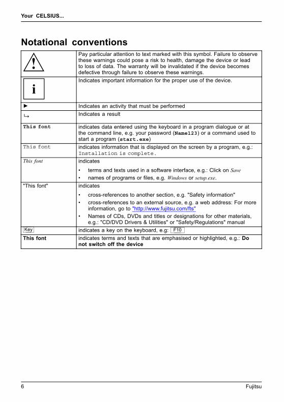
Notational conventionsPay particular attention to text marked with this symbol. Failure to observethese warnings could pose a risk to health, damage the device or leadto loss of data. The warranty will be invalidated if the device becomesdefective through failure to observe these warnings.Indicates important information for the proper use of the device.
► Indicates an activity that must be performedIndicates a result
This font indicates data entered using the keyboard in a program dialogue or atthe command line, e.g. your password (Name123) or a command used tostart a program (start.exe)
This font indicates information that is displayed on the screen by a program, e.g.:Installation is complete.
This font indicates
• terms and texts used in a software interface, e.g.: Click on Save• names of programs or files, e.g. Windows or setup.exe.
"This font" indicates
• cross-references to another section, e.g. "Safety information"• cross-references to an external source, e.g. a web address: For more
information, go to "http://www.fujitsu.com/fts"• Names of CDs, DVDs and titles or designations for other materials,
e.g.: "CD/DVD Drivers & Utilities" or "Safety/Regulations" manualKey indicates a key on the keyboard, e.g: F10
This font indicates terms and texts that are emphasised or highlighted, e.g.: Donot switch off the device
6 Fujitsu

Ports and operating elements
Ports and operating elementsPorts
This chapter presents the individual hardware components of your device. This will provideyou with an overview of the ports and operating elements on the device. Please familiariseyourself with these components before starting to work with your device.
Front
1
234
56
7
9
8
1 = Module bays for 51/4" drives2 = Module bays for 31/2" drives3 = ON/OFF switch4 = Headphone port5 = Microphone jack
6 = USB 2.0 ports7 = USB 3.0 ports8 = Hard disk front panel (removable)9 = Casing lock (optional)
Fujitsu 7

Ports and operating elements
Rear
1
2
3
1 = Alternating voltage socket (AC IN)2 = Ports for external devices
(device-dependent)
3 = Slot covers
8 Fujitsu

Important notes
Important notesImportantnotesNotes
In this chapter you will find information regarding safety which it is essential totake note of when working with your device.
Safety informationSafetyinformationNote
Please note the information provided in the "Safety/regulations" manualand in the following safety notes.
When installing and operating the device, please observe the notes onenvironmental conditions in Chapter "Technical data", Page 55 as well asthe instructions in Chapter "Getting started", Page 13.
When setting up the device, make sure there is clearance all around it so thatthe casing receives enough ventilation. In order to avoid overheating, do notcover the ventilation areas of the monitor or the device.
You must only operate the device if the rated voltage used by thedevice is set to the local mains voltage.
The ON/OFF switch does not disconnect the device from the mainsvoltage. You must remove the mains plug from the mains socket tocompletely disconnect from the mains voltage.
Operate the device only with the casing closed.
Replace the lithium battery on the mainboard in accordance with the instructionsin "Replacing the lithium battery", Page 54.
Caution, components in the system can get very hot.
The activities described in these instructions must always beperformed with the greatest care.
Repairs to the device must only be performed by qualified technicians.Incorrect repairs could put the user at great risk or cause serious damageto the equipment (electric shock, risk of fire).
Transporting the deviceDevice,TransportationRetransportation
Transport all parts separately in their original packaging or in a packaging whichprotects them from knocks and jolts, to the new site.
Do not unpack them until all transportation manoeuvres are completed.
If the device is brought from a cold environment into the room where it will beused, condensation may occur. To avoid damaging the device, wait until it hasreached room temperature and is absolutely dry before initial startup.
Fujitsu 9

Important notes
Cleaning the deviceDevice,TransportationRetransportationSystemunit,seeDevice
Turn off all power and equipment switches and disconnect the powerplug from the mains outlet.
Do not clean any interior parts yourself, leave this job to a service technician.
Do not use any cleaning agents that contain abrasives or may corrodeplastic (alcohol, thinner or acetone).
Never clean the device with water! Water entering into the device couldpresent a serious risk to users (e.g. electric shock).
Ensure that no liquid enters the system.
The surface can be cleaned with a dry cloth. If particularly dirty, use a cloth that has beenmoistened in mild domestic detergent and then carefully wrung out.
Use disinfectant wipes to clean the keyboard and the mouse.
Energy saving, disposal and recyclingDisposalEnergysavingRecyclingDrivers&UtilitiesDVDUserDocumentationDVD
You can find information on these subjects in the "Environment and Energy Information" manualor on our website ("http://www.fujitsu.com/fts/about/fts/environment-care/").
10 Fujitsu

Important notes
CE markingCEmarkingCEmarkingNotesElectromagneticcompatibilityLowvoltagedirective
The shipped version of this device complies with the requirements of EU directives 2004/108/EC"Electromagnetic compatibility", 2006/95/EC "Low voltage directive", 2011/65/EC "RoHS directive"and 2009/125/EC "ecodesign directive".CE marking for devices with radio componentThis equipment complies with the requirements of Directive 1999/5/EC of the European Parliamentand Commission from 9 March, 1999 governing Radio and Telecommunications Equipmentand mutual recognition of conformity.
CE nnnn (!) ; nnnn: For digits and exclamation mark (!), see label on the product.
You can find more information and declarations of conformity on the Internet at:"http://globalsp.ts.fujitsu.com/sites/certificates".
This equipment can be used in the following countries:Belgium Bulgaria Denmark GermanyEstonia Finland France GreeceUK Ireland Iceland ItalyCroatia Latvia Liechtenstein LithuaniaLuxembourg Malta Netherlands NorwayAustria Poland Portugal RumaniaSweden Switzerland Slovakia SloveniaSpain Turkey Czech Republic HungaryCyprusContact the corresponding government office in the respective country for current information onpossible operating restrictions. If your country is not included in the list, then please contactthe corresponding supervisory authority as to whether the use of this product is permitted inyour country.
Fujitsu 11
Important notes
FCC Compliance StatementIf the device complies with the FCC regulations, the FCC sign can be found on the type rating plate.
FCC Class B Compliance StatementDOC (INDUSTRY CANADA) NOTICESNotice to Users of Radios and Television:This class B digital apparatus complies with Canadian ICES-003.
The following statement applies to the products covered in this manual, unless otherwise specifiedherein. The statement for other products will appear in the accompanying documentation.
NOTE:This equipment has been tested and found to comply with the limits for a "Class B" digitaldevice, pursuant to Part 15 of the FCC rules and meets all requirements of the CanadianInterference-Causing Equipment Standard ICES-003 for digital apparatus. These limits aredesigned to provide reasonable protection against harmful interference in a residential installation.This equipment generates, uses and can radiate radio frequency energy and, if not installedand used in strict accordance with the instructions, may cause harmful interference to radiocommunications. However, there is no guarantee that interference will not occur in a particularinstallation. If this equipment does cause harmful interference to radio or television reception,which can be determined by turning the equipment off and on, the user is encouraged totry to correct the interference by one or more of the following measures:
• Reorient or relocate the receiving antenna.• Increase the separation between equipment and the receiver.• Connect the equipment into an outlet on a circuit different from that to
which the receiver is connected.• Consult the dealer or an experienced radio/TV technician for help.Fujitsu is not responsible for any radio or television interference caused by unauthorizedmodifications of this equipment or the substitution or attachment of connecting cables andequipment other than those specified by Fujitsu. The correction of interferences caused by suchunauthorized modification, substitution or attachment will be the responsibility of the user.
The use of shielded I/O cables is required when connecting this equipment to any and all optionalperipheral or host devices. Failure to do so may violate FCC and ICES rules.
12 Fujitsu

Getting started
Getting startedGettingstarted
Please observe the safety information in the "Important notes", Page 9 chapter.
Unpacking and checking the deliveryIt is recommended not to throw away the original packaging material! It may berequired for reshipment at some later date.PackagingContentsofdeliveryPackaging,
► Unpack all the individual parts.► Check the contents of the package for any visible damage caused during transport.► Check whether the delivery conforms to the details in the delivery note.► Should you discover that the delivery does not correspond to the delivery
note, notify your local sales outlet immediately.
Steps for initial setupPreparingforfirstuse,overviewPreparingforuse,
Only a few steps are necessary to put your new device into operation for the first time:
• Select a location for device and set up device• Connect external devices such as mouse, keyboard and monitor• Check the voltage at the mains outlet and connect the device to an electrical outlet• Switch the device onYou will learn more about the individual steps in the following sections.
External devicesIf you have received other external devices in addition to your own device (e.g.a printer), do not connect these until after the initial installation. The followingsections describe how to connect these external devices.
Drives and boardsIf you have received drives or boards with your device, please do not installthem until after first-time setup. How to install drives and boards is describedin the "System expansions", Page 32 chapter.
Fujitsu 13

Getting started
Setting up the deviceWorkstationErgonomicDevice
When installing your device, please read the recommendations and safetynotes in the "Safety/regulations" manual.
We recommend that you place your device on a surface which is not slippery. Inview of the many different finishes and varnishes used on furniture, it is possiblethat the rubber feet will mark the surface they stand on.
Depending on the location of your device, bothersome vibrations and noises mayoccur. To prevent this, a distance of at least 10 mm / 0.39" should be maintainedfrom other devices on casing sides without ventilation surfaces.
In order to avoid overheating, do not cover the ventilation areasof the monitor or the device.
A minimum distance of 200 mm / 7.87" from the device must beobserved for ventilation areas.
Do not stack several devices on top of each other.
Do not expose the device to extreme ambient conditions (see "Technical data", Page 55,section "Ambient conditions"). Protect the device against dust, humidity and heat.
Connecting the machine to the mainsMainsadapter,
21
► Connect the mains cable to the machine (1).► Plug the mains plug into a three-pin socket (2).
After the mains power cable has been attached, the device automatically switchesitself on for a few seconds to run a system test, then switches off again.
14 Fujitsu

Getting started
Connecting external devicesRead the documentation on the external device before connecting it.
With the exception of USB devices, always remove all power plugsbefore connecting external devices!
Do not connect or disconnect cables during a thunderstorm.
Always take hold of the actual plug when disconnecting a cable. Never pull the cable!
Ports on the devicePortsExternaldevicesDevice
The ports are located on the front and back of the device. Not all ports are necessarily present onyour device. The standard ports are marked with the symbols shown below (or similar). Detailedinformation on the location of the ports is provided in the manual for the mainboard.
PS/2 keyboard portKeyboardport
Parallel port/printer (optional)ParallelportPrinter
1 Serial port 1Serialport
2 Serial port 2Serialport
VGA monitor portMonitorport
Microphone portMicrophonejack
HeadphonesHeadphones
Audio input (Line in)AudioinputLinein
Audio output (Line out)AudiooutputLineout
PS/2 mouse portMouseportPS/2mouseport
USB 2.0 - Universal Serial BusUniversalSerialBus LAN LAN port
LANport
USB 3.0 - Universal Serial BusUniversalSerialBus
SCSI connection
DVI-I monitor port DP DisplayPort
Some of the connected devices require special software (e.g. drivers) (refer to thedocumentation for the connected device and operating system).
Fujitsu 15

Getting started
Connecting a monitorIn the factory settings, the system is configured so that an available PCI displayadapter is provided for screen output during initial setup.
This is also the case if there is an internal display adapter.
As soon as a PCI display adapter is plugged in or if the CPU has no graphicscore, all onboard display adapter ports are covered ex works.
Depending on the configuration, you can use the monitor ports on the mainboard (1) or the monitorports for an optional display adapter in one of the board slots (2) to connect a monitor to your device.
If you equip a device with an integrated display adapter and an optional display adapter, theintegrated display adapter is initially deactivated on attaching the optional display adapter. If bothdisplay adapters are to be operated, you must first activate this function in the BIOS setup.
1
2
1 = Monitor ports of the mainboard (onlyprocessors with graphics core)
2 = Monitor ports of the optionaldisplay adapter
Only attach the monitor to your device when it is switched off.
► Follow the instructions contained in the monitor manual to prepare the monitorfor operation (e.g. connecting cables).
► Connect the data cable to a suitable monitor port on the device (DVI-I, DisplayPort).
16 Fujitsu

Getting started
If an additional display adapter other than the CPU display adapter isplugged into the system, only one additional monitor is provided for displayon the onboard display adapter. The two others act as ServicePorts andare not intended for simultaneous image playback.
The DisplayPort is the preferred port. Therefore, the cover here can be broken off withthe help of a predetermined breaking point, in order to make the port accessible. If aDVI or VGA port is required, the display adapter cover must be removed.
Connecting the mouseYou can connect a USB mouse or a PS/2 mouse to your device.Mouse,Connecting,
Connecting a USB mouse► Connect the USB mouse to one of the USB ports on the device.
USBport,USBport
Connecting a PS/2 mouseThe PS/2 mouse is only detected by the device if you connect the mouse whenthe device is switched off and then switch the device on again.
► Switch your device off.
If you do not attach a mouse to the PS/2 mouse port, you can disable the mousecontroller in the BIOS Setup in order to free the IRQ12 for a different application.
► Connect the PS/2 mouse to the PS/2 mouse port of the device.PS/2mouse,Connecting,PS/2mouse,
► Switch your device on again.
Fujitsu 17

Getting started
Connecting the keyboardYou can connect a USB keyboard or a PS/2 keyboard to your device.Keyboard,Connecting,
Connecting a USB keyboardUse the supplied keyboard cable only.USBport,Connecting,
► Insert the flat rectangular USB plug of the keyboard cable into one of the device’s USB ports.USBport
Connecting a PS/2 keyboardUse the supplied keyboard cable only.ConnectingaPS/2keyboardConnecting,
The PS/2 keyboard is only detected by the device if you connect the keyboardwhen the device is switched off and then switch the device on again.
► Switch your device off.► Plug the round plug of the keyboard cable into the keyboard port on the device.
Keyboard,
► Switch your device on again.
Connecting external devices to the parallel(optional) or serial portParallelportSerialportParallelportSerialportExternaldevicesDevices
External devices can be connected to the parallel or serial port (e.g. a printer or a scanner).
► Connect the data cable to the external device.► Depending on the device, connect the data cable to the parallel port or the serial port.
For an exact description of how to connect external devices to the correspondingport, please refer to the documentation of the external device.
Port settingsParallelportSerialport,
You can change the port settings (e.g. address, interrupt) in the BIOS Setup.
Device driversDevicedriversDevicedrivers,
The devices connected to the parallel or serial port require drivers. Your operatingsystem already includes many drivers. If the required drive is missing, install it. Currentdrivers are usually available on the Internet or will be supplied on a data carrier.
18 Fujitsu

Getting started
Connecting external devices to the USB portsUSBdevices,USBport,Externaldevices,Devices,
You can connect a wide range of external devices to the USB ports (e.g.printer, scanner, mouse or keyboard).
USB devices are hot-pluggable. This means you can connect and disconnectUSB cables while your device is switched on.
Additional information can be found in the documentation for the USB devices.
► Connect the data cable to the external device.► Connect the data cable to one of the USB ports on your device.
Device driversThe external USB devices you connect to the USB ports usually require no driver of theirown, as the required software is already included in the operating system. If the devicerequires separate software, please note the information in the manufacturer’s manual.
Switching on for the first time: installing the softwareInstalling,Software,Installing,
Once the installation has been started the device must not be switchedoff, unless the installation has been completed.
During installation, the device may only be rebooted when you are requested to do so!
The installation will otherwise not be carried out correctly and the contentsof the hard disk must be completely restored.
If the device is integrated into a network, the user and server details as well asthe network protocol are required during the software installation.
Contact your network administrator if you have any questions about these settings.
When you switch on the device for the first time, the supplied softwareis installed and configured. Plan a reasonable amount of time for this,as this process must not be interrupted.
You may need the licence number for Windows during the installation. You can find the licencenumber as a label on your device (no longer applies to Windows 8 or higher).
Fujitsu 19

Getting started
Switching on monitor and deviceDevice,Monitor,
In order to avoid overheating, do not cover the ventilation areasof the monitor or the device.
► Switch the monitor on (see the operating manual for the monitor).► Switch the device on. To do this, follow the instructions below.
Switching on the device
► Press the ON/OFF switch on the front of the device.The power indicator lights up and the device starts.
Installing the software► During installation, follow the on-screen instructions.
Software,Installing,
► If anything is unclear regarding the data you are asked to input, read theonline Help in your operating system.
You will find more information on the system, as well as drivers, utilities and updates onthe "Drivers & Utilities" DVD and on the Internet at "http://www.fujitsu.com/fts/support".
You can find information and help on the Windows operating system functionson the Internet at "http://windows.microsoft.com".
20 Fujitsu

Operation
OperationIndicators on the device
1
23
No. indicator Description1 Drive indicators The indicator lights up when the CD-ROM or DVD drive of the
device is accessed. You must never under any circumstancesremove the CD/DVD while the indicator is lit.
2 Power-on indicator • The indicator is illuminated:The device is switched on.
• The indicator is flashing:The device is in energy-saving mode. After being switched onwith the ON/OFF switch, the device powers up or returns to thestate it was in before it entered energy-saving mode.
• The indicator is not illuminated:The device is disconnected from the mains or is ready. If thedevice is ready it can be switched on with the ON/OFF switch.
3 Hard disk indicator The indicator lights up when the hard disk drive in the deviceis being accessed.
In energy-saving mode the device must not be disconnected from themains supply, as data loss may occur.
Switch the device on► If necessary, switch the monitor on (see the operating manual for the monitor).
Device,Monitor,
► Press the ON/OFF switch on the front of the device.The power indicator lights up and the device starts.
Fujitsu 21

Operation
Switching off the device► Shut down the operating system in a defined manner. In Windows: via the
Start menu and the Turn Off Computer function.Device,Monitor,
or► Briefly press the ON/OFF switch.
► If the operating system does not automatically switch the device into energy-savingmode or switch it off, press the ON/OFF switch until the device switches off.Warning, this could lead to a loss of data!If the device is switched off, the device consumes a minimum of energy.
The ON/OFF switch does not disconnect the device from the mains voltage. Tocompletely disconnect the mains voltage, remove the power plug from the power socket.
► If necessary, switch the monitor off (see the operating manual for the monitor).
22 Fujitsu

Operation
KeyboardKeyboardKeyboard,Keyboard,Keyboard,Keyboard,Keyboard,AlphanumerickeypadCursorkeysKeys,FunctionkeysNumerickeypadNumerickeypad
The illustrated keyboard is an example and may differ from the model you use.
1 2
3 4 5
1 = Function keys2 = On/off switch (optional)3 = Alphanumeric keypad
4 = Cursor keys5 = Numeric keypad (calculator keypad)
Important keys and keyboard shortcutsKeysKeyboardshortcuts
The description of the following keys and keyboard shortcuts applies to Microsoftoperating systems. Details of other keys and keyboard shortcuts can be found inthe documentation for the relevant application program.
Key / key combination DescriptionON/OFFswitchButton,
On/off switch (optional)Depending on the setting in the BIOS Setup, the device can be switchedon or off with this switch. Some operating systems allow you to configureadditional functions of the ON/OFF switch in the Control Panel.
With some keyboards the ON/OFF switch can only be used with an ACPI(Advanced Configuration and Power Management Interface). Otherwisethe key is inoperative. The mainboard must support this function.Keys,Keys,Keys,
Enter keyconfirms the highlighted selection. The Enter key is also referred to asthe "Return" key.
Fujitsu 23

Operation
Key / key combination DescriptionKeys,
Windows key (device-dependent: variant 1)calls up the Windows Start menu.Keys,
Menu key (device-dependent: variant 1)calls up the menu for the marked item (Windows).Keys
Windows key (device-dependent: variant 2)Switches between the start screen and the last used application.
Keys
Menu key (device-dependent: variant 2)Opens the menu for the active application.
Keys,Keys,
Shift keyenables upper-case letters and the upper key symbols to be displayed.Keys,
Alt Gr key (country-dependent)produces a character shown on the bottom right of a key (e.g. the @sign on the Q key).Keys,
Num Lock keyBy pressing the Num Lock key you switch between the upper- andlower-case levels of the calculator keypad.
When the Num Lock indicator is lit the numeric keypad and arithmetickeys are active.
When the Num Lock indicator is not lit the cursor control functions on theNumeric keypad are active.
Ctrl
Keys,KeysKeysKeys,
Ctrl keyperforms a special operation when pressed in conjunction with anotherkey. The Ctrl key is also called the "Control" or "Control key".
AltCtrl Del+ +
Ctrl+Alt+DelCtrl+Alt+DelKeyskeyboardshortcuts
Windows Security/Task ManagerThis key combination opens the Windows Security/Task Manager window.
Settings in BIOS SetupBIOSSetup,Systemsettings,BIOSSetup,BIOSSetup,BIOSSetupSetup,
In BIOS Setup, you can set the system functions and the hardware configuration of the device.When the PC is delivered, the default entries are valid (see "BIOS Setup" manual or manual forthe mainboard). You can customise these settings to your requirements in the BIOS Setup.
24 Fujitsu

Operation
Property and data protectionPropertyprotectionDataprotectionSecuritymeasures
Software functions and mechanical locking offer a broad range of functions for protecting your deviceand your personal data against theft and unauthorised access. You can also combine these functions.
Anti-theft protection and lead-sealingDevice,Device,Casing,Lead-sealingAnti-theftprotectionSecurityLockChain
1
2
1 = Holes for padlock 2 = Device for Security Lock
Anti-theft protectionYou can protect your device from theft
• with the Security Lock device (1) and with a Kensington MicroSaver. Consultthe manual for your Security Lock.
• with the holes (2) and a padlock and chain which you have connected to a fixed object beforehand.
Lead-sealingTo prevent unauthorised persons from opening the casing, the casing can be lead-sealed. To dothis, feed the sealing chain through the holes (2) and seal the chain with the lead seal.
Fujitsu 25

Operation
Mechanical casing lock (optional)Casingmechanical lockCasingLockCasing lock
With the casing lock you can mechanically lock the casing to prohibit unauthorised personsfrom opening it. The keys can be found on the rear panel of your device.
If you use a casing with a casing lock, the safety guard in front of the drivesis also secured against unauthorised opening.
2
1
Locking the casing► Turn the key in the direction of the arrow (1).
Unlocking the casing► Turn the key in the direction of the arrow (2).
BIOS setup security functionsSecurityfunctionsBIOSSetup
The Security menu in BIOS Setup offers you various options for protecting yourpersonal data against unauthorized access, e.g.:
• Prevent unauthorized access to BIOS Setup• Prevent unauthorised system access• Prevent unauthorised access to the settings of boards with their own BIOS• Activate virus warnings• Protect BIOS from overwriting• Protect the device from being switched on by an external deviceYou can also combine these functions.
You will find a detailed description of the Security menus and how to assign passwordsin the manual for the mainboard or in the "BIOS Setup" manual.
26 Fujitsu

Operation
Access authorisation via SmartCardSecurityfunctionsAccesspermission,SmartCard
In systems equipped with a SmartCard reader, access can be restricted to thoseusers who have a corresponding SmartCard.
Operating the SmartCard reader (optional)Operation of this module is not permitted in Taiwan.
► Connect the external SmartCard reader to your system as described inthe instructions for the SmartCard reader.SmartCard reader,
After the device is switched on, you will be prompted to insert your SmartCard.
Fujitsu 27

Troubleshooting and tips
Troubleshooting and tipsRefer to the safety notes in the "Safety/regulations" manual and in the "Gettingstarted", Page 13 chapter when connecting or disconnecting cables.
If a fault occurs, try to correct it as described in the following documentation:
• in this chapter• in the documentation for the connected devices• in the help systems of the software used• in the documentation for your operating system
Help if problems occurShould you encounter a problem with your computer that you cannot resolve yourself:
► Note the ID number of your device. The ID number is found on the type ratingplate on the back, the underside or the top of the casing.
► For further clarification of the problem, contact the Service Desk for your country (see theService Desk list or visit the Internet at "http://support.ts.fujitsu.com/contact/servicedesk"). Whenyou do this, please have ready the identity number and serial number of your system.
TroubleshootingPower-on indicator remains unlit after you haveswitched on your deviceCause TroubleshootingThe mains voltage supply is faulty. ► Check whether the power cable is plugged
properly into the device and a groundedmains outlet.
Internal power supply overloaded. ► Pull the power plug of the device out of themains outlet.
► Wait approx. 3 min.► Plug the power plug into a properly grounded
mains outlet again.► Switch the device on.
28 Fujitsu

Troubleshooting and tips
The device cannot be switched off with the ON/OFF switch.Cause RemedySystem crash ► Keep the on/off switch pressed for at least 4
seconds until the machine switches off.Caution: This can lead to a loss of data!
This procedure does not allow the operatingsystem to shut down in an orderly way. The nexttime the system is started there may well beerror messages.
Monitor remains blankCause RemedyMonitor is switched off. ► Switch your monitor on.Power saving has been activated (screen isblank)
► Press any key on the keyboard.
or► Deactivate the screen saver. If
necessary, enter the appropriatepassword.
Brightness control is set to dark ► Adjust the brightness control. For detailedinformation, please refer to the operatingmanual supplied with your monitor.
Power cable not connected ► Switch off the monitor and the device.► Check that the monitor power cable is
properly connected to the monitor and toa grounded mains outlet or to the monitorsocket of the device.
► Check that the device power cable isproperly plugged into the device and agrounded mains outlet.
► Switch on the monitor and the device.Monitor cable not connected ► Switch off the monitor and the device.
► Check that the monitor cable is properlyconnected to the device and monitor.
► Switch on the monitor and the device.Incorrect setting for the monitor ► Restart the system.
► Press F8 while the system is booting.► Start the system in Safe Mode.► Set up the monitor as described in the
documentation for your operating systemand monitor.
Fujitsu 29

Troubleshooting and tips
No mouse pointer displayed on the screenCause RemedyThe mouse is not correctly connected. ► Shut down the operating system properly.
► Switch the device off.► Check that the mouse cable is properly
connected to the system unit. If you use anadapter or extension lead with the mousecable, check the connections.
► Switch the device on.The mouse controller is not enabled. ► Check in the BIOS-Setup whether the mouse
controller is enabled.► Check that the mouse driver is properly
installed and is present when the applicationprogramme is started. Detailed informationcan be found in the user guide for the mouseand application programme.
Time and/or date is not correctCause RemedyTime and date are incorrect. ► Set the correct time and date within the
operating system you are using.
or► Set the correct time and/or date in the
BIOS Setup.The lithium battery is discharged. ► If the time and date are repeatedly wrong
when you switch on your device, replace thelithium battery (see "Replacing the lithiumbattery", Page 54).
Error messages on the screenError messages and their explanations are provided:
• in the technical manual for the mainboard• in the documentation for the programs used
Installing new softwareWhen installing programs or drivers, important files may be overwritten and modified. Tobe able to access the original data in the event of any problems following installation,you should backup your hard disk prior to installation.
30 Fujitsu

Troubleshooting and tips
Restoring the hard disk contentsYou will find the instructions for restoring the contents of the hard disk in the "Recovery Guide" manual.
TipsTopic TipLack of system resources ► Close unnecessary applications.
or► Run the applications in a different order.
Other manuals Further manuals are provided as PDF files onthe "Drivers & Utilities" DVD.
Fujitsu 31

System expansions
System expansionsUpgrades,Device,SystemexpansionComponentsServicing
Repairs to the device must only be performed by qualified technicians. Incorrect repairsmay greatly endanger the user (electric shock, fire risk) and will invalidate your warranty.
After consulting the Hotline/Help Desk, you may remove and install the componentsdescribed in this manual yourself.
As the device has to be shut down in order to install/deinstall system hardwarecomponents, it is a good idea to print out the relevant sections of this chapter beforehand.
The following illustrations may differ slightly from your device, depending on its configuration level.
If further documentation was delivered with your device, please also read this through carefully.
In addition, before removing or installing system components, please pay attention to the following:
The device must be switched off when installing/removing the systemexpansions and may not be in energy-saving mode.
Remove the power plug before opening the device.
Be careful that no wires become trapped when removing or installing components.
When installing components that become very hot, make sure that the maximumpermissible temperature of the components in operation is not exceeded.
An update of the BIOS may be required for a system expansion or hardwareupgrade. Further information can be found in the BIOS help section or ifnecessary in the Technical Manual for the mainboard.
32 Fujitsu

System expansions
Information about boardsTake care with the locking mechanisms (catches and centring pins) when youare replacing boards or components on boards.
Note that some components on the mainboard may be very hot if the device wasin use shortly before the casing was removed.
To prevent damage to the board or the components and conductors on it, please take care whenyou insert or remove boards. Make sure expansion boards are inserted straightly.
Never use sharp objects (screwdrivers) for leverage.
Boards with electrostatic sensitive devices (ESD) are identifiable by the labelshown.
When handling boards fitted with ESDs, you must always observe thefollowing points:
• You must always discharge static build up (e.g. by touching a groundedobject) before working.
• The equipment and tools you use must be free of static charges.• Only touch or hold the boards by the edge or, if present, at the areas
marked green (Touch Points).• Never touch pins or conductors on boards fitted with ESDs.
Fujitsu 33

System expansions
Opening the casingCasing,Device,
► Switch the device off. The device must not be in power-saving mode.
Please observe the safety information in "Important notes", Page 9.
Disconnect the mains plug from the mains outlet.
Only insert the power plug after you have closed the casing.
► Remove any connected wires which are in the way.► On devices with a casing lock: Unlock the casing.► Lay the device on its side in the manner shown.
1
2
► Pull the locking device (1) and swivel the side part in the direction of the arrow (2).
34 Fujitsu

System expansions
Closing the casing► Insert the side part in the guide rail on the lower part of the casing.
Casing,Device,
1
► Swivel the side cover in the direction of the arrow (1) until it engages.► On devices with a casing lock: Lock the casing.► Reconnect the cables that you disconnected before.
Overview of drive bays and drives in your deviceThe casing can accommodate multiple accessible and non-accessible drives:
• two drive bays for accessible 51/4" drives• two drive bays for accessible 31/2" drives• Drive bays for multiple non-accessible 21/2" and 31/2" drives (hard disks):
• two 31/2 inch drives (HDD)• one 21/2 inch drive (HDD)
In addition, the power version offers drive bays for two non-accessible 31/2 inch drives (HDD).
"Accessible drives" are e.g. DVD or CD ROM drives, into which a data medium can beinserted from outside. "Non-accessible drives" are for example hard disk drives.
Fujitsu 35

System expansions
Installing and removing the accessible 51/4 inch driveThe following chapter illustrates the standard version and not the power version. However,the procedure in the following chapters is the same for both versions.
Fitting the drive cover for the 5 1/4 inch driveTo use the latch function of the accessible 51/4 inch drive, you must fit the correspondingdrive cover before installing the drive in the casing. Proceed as follows:
► Open the casing (see "Opening the casing", Page 34).
1
► Remove the drive cover from the bracket in the direction of the arrow (1).
1
► Connect the drive cover to the drive (1).
36 Fujitsu

System expansions
Installing an accessible drive► Open the casing (see "Opening the casing", Page 34).► If you are installing the drive in the upper bay and a cover (optional) is
already in place, please remove it.
or► If you are installing the drive in the lower bay and a cover (optional) is
already in place, please remove it.► Break out the pre-stamped metal cover on the drive bay.
► Fit the drive cover for the 51/4 inch drive (see "Fitting the drive cover forthe 5 1/4 inch drive", Page 36).
Do not throw away the cover. For cooling and protection against fire you must refit thecover if you remove the drive again later (see "Removing an accessible drive", Page 38).
1
► Slide the accessible drive into the casing until it snaps in place (1).► Connect the cables to the drive. Make sure the polarity is correct.► Close the casing (see "Closing the casing", Page 35).
It may be necessary to modify the entry for the drive in the BIOS Setup.
Fujitsu 37
System expansions
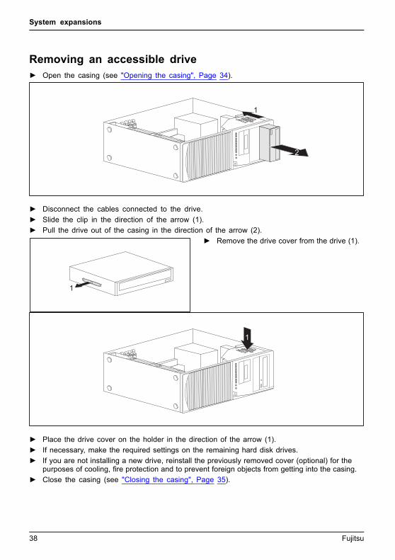
Removing an accessible drive► Open the casing (see "Opening the casing", Page 34).
1
2
► Disconnect the cables connected to the drive.► Slide the clip in the direction of the arrow (1).► Pull the drive out of the casing in the direction of the arrow (2).
1
► Remove the drive cover from the drive (1).
1
► Place the drive cover on the holder in the direction of the arrow (1).► If necessary, make the required settings on the remaining hard disk drives.► If you are not installing a new drive, reinstall the previously removed cover (optional) for the
purposes of cooling, fire protection and to prevent foreign objects from getting into the casing.► Close the casing (see "Closing the casing", Page 35).
38 Fujitsu

System expansions
It may be necessary to modify the entry for the drive in the BIOS Setup.
Installing/removing the SmartCard reader and/orWLAN module (optional, 3½-Zoll)You can also install a SmartCard reader and/or a WLAN module for wireless LAN (Local AreaNetwork) or a memory card reader in the drive bays for 3½ inch drives (see "Removing andinstalling the memory card reader (optional, 3½ inch, MultiCard)", Page 44).
The SmartCard reader and WLAN module can be installed together in onemodule holder (optional). If you have ordered a device with a WLAN moduleand SmartCard reader, the module holder, SmartCard reader and WLANmodule will already be installed at the time of delivery.
However, you can only install one of the two boards. The WLAN module is installedin the lower slot of the carrier and the SmartCard reader in the upper slot of thecarrier. If you want to install the SmartCard reader and the WLAN module together,first install the WLAN module. Removal is performed in the reverse order.
If you have ordered a device without a WLAN module or SmartCard reader,a blind cover is installed instead of the module holder.
Installing/removing a 3½" reader in a 3½" bay(optional, SmartCard or MultiCard)The following chapter illustrates the standard version and not the power version. However,the procedure in the following chapters is the same for both versions.
Operation of the module is not permitted in Taiwan.
You can for instance install a SmartCard or MultiCard reader in the 3½" drive bay. Thereader is mounted onto a module holder when installed in the casing.
SmartCard or MultiCard readers can be mounted on a module holder (optional).If you have ordered a device with a SmartCard or MultiCard reader, the moduleholder, SmartCard or MultiCard reader are already built in on delivery.
If you have ordered a device without a SmartCard or MultiCard reader, ablind cover is installed instead of the module holder.
Fujitsu 39

System expansions
Removing the module holder► Open the casing (see "Opening the casing", Page 34).► Disconnect the cables connected to the module holder.
11
2
► Remove the screws (1) on the module holder.► Push the module holder out of the casing in the direction of the arrow (2).
Screwing the WLAN module onto the module holder
2
a
a1
2
► Push the WLAN module - with thecomponent side facing downwards - inthe direction of the arrow (1) into theguide on the module holder (a).
► Fasten the WLAN module with thescrews (2).
40 Fujitsu

System expansions
Screwing the SmartCard reader onto the module holder
2
2
a
a
1
► Push the SmartCard reader - with thecomponent side facing downwards - intothe guide on the module holder (a) inthe direction of the arrow (1).
► Secure the SmartCard reader withthe screws (2).
Installing the module holder with SmartCard readerand/or WLAN module
22
1
► Push the module holder into the casing in the direction of the arrow (1).► Fasten the module holder with the screws (2).► Connect the cables to the boards and the mainboard. Make sure the polarity is correct.► Close the casing (see "Closing the casing", Page 35).
Fujitsu 41

System expansions
Removing the module holder with SmartCard readerand/or WLAN module► Open the casing (see "Opening the casing", Page 34).► Disconnect the cables connected to the module holder.
11
2
► Remove the screws (1).► Push the module holder out of the casing in the direction of the arrow (2).► Remove the SmartCard reader and WLAN module from the module holder (see "Removing
the SmartCard reader from the module holder", Page 43 and "Removing the WLAN modulefrom the module holder", Page 43) and install the module holder again (corresponds to"Installing the module holder with SmartCard reader and/or WLAN module", Page 41).
or► Remove the SmartCard reader and WLAN module from the module holder (see "Removing
the SmartCard reader from the module holder", Page 43 and "Removing the WLAN modulefrom the module holder", Page 43) and install a blind cover in the drive bay.
► Close the casing (see "Closing the casing", Page 35).
42 Fujitsu

System expansions
Removing the SmartCard reader from the module holder
1
1► Undo the screws (1).► Pull the SmartCard reader out of the module
holder in the direction of the arrow (2).
Removing the WLAN module from the module holder
2
a
a1
2
► Undo the screws (1).► Pull the WLAN module out of the module
holder in the direction of the arrow.
Fujitsu 43

System expansions
Removing and installing the memory card reader(optional, 3½ inch, MultiCard)You can also install a memory card reader or a SmartCard reader and/or a WLAN module forwireless LAN (Local Area Network) in the drive bay for 3½ inch drives (see "Installing/removingthe SmartCard reader and/or WLAN module (optional, 3½-Zoll)", Page 39).
The memory card reader can, unlike the SmartCard reader and WLAN module,be installed directly in the device without a module holder.
Installing the memory card reader
22
1
► Push the memory card reader into the casing in the direction of the arrow (1).► Fasten the memory card reader with the screws (2).► Connect the cables to the memory card reader and to the mainboard.
Make sure the polarity is correct.► Close the casing (see "Closing the casing", Page 35).
44 Fujitsu

System expansions
Removing the memory card reader► Open the casing (see "Opening the casing", Page 34).► Disconnect the cables connected to the memory card reader.
11
2
► Remove the screws (1).► Slide the memory card reader out of the casing in the direction of the arrow (2).► Install a blind cover in the drive bay.► Close the casing (see "Closing the casing", Page 35).
Fujitsu 45

System expansions
Installing and removing the hard disk driveThe following description applies both to 31/2 inch drives and to 21/2 inch drives.The installation and removal procedure is the same for both types.
You can find EasyChange rails for a second 31/2 inch hard disk driveon the drive cage. EasyChange rails for a second 21/2 inch hard diskdrive are provided together with the drive.
1 2
3
1 = 21/2 inch hard disk2 = 31/2 inch hard disks
3 = 31/2 inch hard disks (only in power version))
46 Fujitsu

System expansions
Installing a hard disk drive► Open the casing (see "Opening the casing", Page 34).
► Secure the EasyChange rails to the side of the hard disk drive by inserting the upperpins of the EasyChange rail in the corresponding holes of the hard disk.
1
► Slide the hard disk drive with the EasyChange rails into the drive cage in the direction of the arrow(1). Check that the component side of the hard disk drive faces inwards towards the casing floor.
► Connect the cables to the hard disk drive.► Close the casing (see "Closing the casing", Page 35).
It may be necessary to modify the entry for the drive in the BIOS Setup.
Fujitsu 47

System expansions
Removing the hard disk drive► Open the casing (see "Opening the casing", Page 34).
1
1 2
► Slightly press together the EasyChange rails mounted on the hard disk drive (1) and carefullypull the hard disk drive slightly out of the drive cage in the direction of the arrow (2).
► Disconnect the cables connected to the hard disk drive.► Slightly press together the EasyChange rails mounted on the hard disk drive (1) and pull the
hard disk drive completely out of the drive cage in the direction of the arrow (2).
► Pull the EasyChange rails off the hard disk drive.► If you no longer need the EasyChange rails, secure them again at their location in the drive cage.
It may be necessary to modify the entry for the drive in the BIOS Setup.
48 Fujitsu

System expansions
Installing and removing a boardYou can install additional modules in order to increase the performance of your machine.
The number, position and arrangement of the board slots on the mainboard can be found inthe manual for the mainboard. Boards may already be installed on shipment.
The following chapter illustrates the standard version and not the power version. However,the procedure in the following chapters is the same for both versions.Board,Board,
Installing a boardIf possible, always install display adapters in the second slot from the right.
► Open the casing (see "Opening the casing", Page 34).Board
1
22
► Push the retaining clip (1) towards the slot cover to unlock it, then moveit towards the back panel of the device.
► Pull the slot cover out of the slot in the direction of the arrow (2).
Fujitsu 49

System expansions
Do not throw away the slot cover. For cooling, protection against fire and in order tocomply with EMC regulations, you must refit the slot cover if you remove the board.
2
1
► Push the board into the slot (1).► Swivel the retaining clamp back again until you feel it click into place (2).► Connect the cables to the board.► For display adapters with an additional power connection (< 65 W): attach the
display adapter power cable to the power supply.► Close the casing (see "Closing the casing", Page 35).
If you have installed or removed a board, please check the relevant slotsettings in the BIOS Setup. If necessary, change the settings. Furtherinformation is provided in the board documentation.
50 Fujitsu

System expansions
Removing a board► Open the casing (see "Opening the casing", Page 34).
Board
► Disconnect the cables connected to the board.
1
2
► Push the retaining clip (1) towards the slot cover to unlock it, then moveit towards back panel of the device.
► Pull the board out of the slot in the direction of the arrow (2).► Place the board in suitable packaging.
For cooling, protection against fire, and in order to comply with EMC (electromagneticcompatibility) regulations, you must refit the slot cover.
2
1
2
► Slide the slot cover into the slot (1).
Fujitsu 51

System expansions
► Press on the retaining clip until it you feel it engage (2).► Close the casing (see "Closing the casing", Page 35).
If you have installed or removed a PCI board, please check the relevant PCIslot settings in the BIOS Setup. If necessary, change the settings. Furtherinformation is provided in the PCI board documentation.
Replacing the processor► Open the casing (see "Opening the casing", Page 34).► Remove the heat sink (see "Removing the heat sink", Page 52).► Replace the processor as described in the manual for the mainboard.► Install the heat sink again (see "Installing the heat sink", Page 52).► Close the casing (see "Closing the casing", Page 35).
Installing and removing processor cooling devicesRemoving the heat sinkThe shape and position of the heat sink are device-dependent.
► Open the casing (see "Opening the casing", Page 34).► Undo the screws on the heat sink.► Lift the heat sink out of the casing.
You can now replace the processor.
Installing the heat sink► Open the casing (see "Opening the casing", Page 34).► Reinstall the heat sink so that the air flow is fed towards the back of the
casing (see arrow on the heat sink).► Tighten the screws.
Never attach or detach fans during operation. This can cause problemscontrolling the mainboard fan.
52 Fujitsu

System expansions
Mainboard expansionsDetails on how to upgrade the main memory or the processor of your devicecan be found in the manual for the mainboard.UpgradesLithiumbatteryProcessorMainmemoryMainboard
Upgrading main memory► Open the casing (see "Opening the casing", Page 34).
Mainmemory
► Upgrade the main memory according to the description in the manual for the mainboard.► Close the casing (see "Closing the casing", Page 35).
Fujitsu 53

System expansions
Replacing the lithium batteryIn order to permanently save the system information, a lithium battery is installed to providethe CMOS-memory with a current. A corresponding error message notifies the user when thecharge is too low or the battery is empty. The lithium battery must then be replaced.
Incorrect replacement of the lithium battery may lead to a risk of explosion!
The lithium battery may be replaced only with an identical battery or witha type recommended by the manufacturer.
Do not dispose of lithium batteries with household waste. They must be disposedof in accordance with local regulations concerning special waste.
Make sure that you observe the correct polarity when replacing the lithiumbattery. The plus pole must be on the top!Lithiumbattery,Replacing,Replacing,Replacing, lithiumbatteryBattery
The lithium battery holder exists in different designs that function in the same way.
12 3
1
23
► Press the catch in the direction of the arrow (1).The battery jumps out of the holder slightly.
► Remove the battery (2).► Push the new lithium battery of the identical type into the holder (3) and
press it down until it engages.
54 Fujitsu

Technical data
Technical dataElectrical dataSafety standards complied with: IEC 60950-1, EN 60950-1, UL 60950
CSA 22.2 No.60950-1Protection class: IRated voltage range 100 V – 240 VRated frequency 50 Hz – 60 HzMax. rated current
3.5 A - 1.5 ADimensionsWidth x Depth x Height: 175 mm x 419 mm x 395 mm /6.89 in x 16.5
in x 15.55 inWeightin basic configuration: ca. 11 kg / 24.25 lbsAmbient conditionsEnvironment class 3K2
Environment class 2K2
DIN IEC 721 part 3-3
DIN IEC 721 part 3-2TemperatureOperation (3K2) 10 °C .... 35 °C /50 °F ... 95 °FTransportation (2K2) –25 °C .... 60 °C /–13 °F ... 140 °FThe formation of condensation is not permitted while the device is in operation !
Clearance required to ensure adequate ventilation:without air vents
with air vents
min. 10 mm / 0.39 inch
min. 200 mm / 7.87 inch
The data sheets of these devices contains further technical data. The data sheetscan be found on our website at "http://www.fujitsu.com/fts/".
Fujitsu 55

Index
IndexAAccess permission, SmartCard 27Alphanumeric keypad 23Anti-theft protection 25Audio input 15Audio output 15
BBattery 54BIOS Setup 24
security functions 26BIOS Setup,
configuration 24settings 24system settings 24
Boardinstalling 49removing 51
Board,installing 49removing 49
Button,ON/OFF switch 23
CCasing
Mechanical lock 26Casing lock 26Casing mechanical lock 26Casing,
closing 35Lead-sealing 25opening 34
CE marking 11Chain 25Components
installing/removing 32Connecting a PS/2 keyboard 18Connecting,
keyboard 18mouse 17PS/2 keyboard 18PS/2 mouse 17USB keyboard 18
Contents of delivery 13Ctrl+Alt+Del 24Cursor keys 23
DData protection 25Device
Connections 15setting up 14
Device driversParallel port 18
Device drivers,Serial port 18
Device,Anti-theft protection 25closing 35Lead-sealing 25opening 34switching off 22switching on 20–21transporting 9–10upgrades 32
Devicesconnecting 18
Devices,connecting 19
Disposal 10Drivers & Utilities DVD 10
EElectromagnetic compatibility 11Energy saving 10Ergonomic
Workstation 14External devices
connecting 18Ports 15
External devices,connecting 19
FFunction keys 23
GGetting started 13
HHeadphones 15
IImportant notes 9
56 Fujitsu
Index
Installing,software 19–20switching on for the first time 19
KKeyboard 23Keyboard port 15keyboard shortcuts 24Keyboard shortcuts 23Keyboard,
alphanumeric keypad 23connecting 18cursor keys 23function keys 23numeric keypad 23port 18
Keys 23Ctrl 24Ctrl+Alt+Del 24Menu key 24
Keys,Alt Gr 24Control 24Ctrl key 24cursor keys 23Enter 23Enter key 23menu key 24Num Lock 24Return 23shift 24shift key 24Start key 24
LLAN port 15Lead-sealing 25Line in 15Line out 15Lithium battery 53Lithium battery,
replacing 54Lock 26Low voltage directive 11
MMain memory 53
upgrading 53Mainboard
Upgrades 53Mains adapter,
connecting 14
Microphone jack 15Monitor port 15Monitor,
switching off 22switching on 20–21
Mouse port 15Mouse,
connecting 17
NNote
safety 9Notes
CE marking 11important 9
Numeric keypad 23
OON/OFF switch 23Overview
Device 5
PPackaging 13Packaging,
unpacking 13Parallel port 15, 18
Connecting devices 18Settings 18
Ports 7, 15Preparing for first use, overview 13Preparing for use,
overview 13Printer 15Processor 53Property protection 25PS/2 mouse port 15PS/2 mouse,
connecting 17port 17
RRecycling 10Replacing,
lithium battery 54Replacing, lithium battery 54Retransportation 9–10
SSafety information 9
Fujitsu 57

Index
Security functionsBIOS Setup 26SmartCard 27
Security measures 25SecurityLock 25Serial port 15, 18
Connecting devices 18Serial port,
Settings 18Servicing 32Setup,
see BIOS Setup 24SmartCard reader,
operating 27Software,
installing 19–20System expansion 32System settings,
BIOS Setup 24System unit, see Device 10
TTransportation 9–10
UUniversal Serial Bus 15Upgrades
Mainboard 53Upgrades,
device 32USB devices,
connecting 19USB port 17–18USB port,
connecting devices 19connecting keyboard 18connecting the mouse 17
User Documentation DVD 10
WWorkstation 14
58 Fujitsu