Embed Size (px)
Citation preview

. fujimoto ENLARGER§7;(0)computer
OPERATING INSTRUCTIONS
II:I
I,!
i~i~i-""
~UCKY
Enlarger.
Thank you very much for purchasing the "FUJIMOTO" G70 Computer
Please read this instruction manual thoroughly before
you use the equipment, so that you can fully take advantage of
its superb performance.
CON TEN T S
SPECIFICATION & PERFORMANCE . . . . . . . . . . . . . . . . . . . .
PROG RAM FOR REFERENC E PRINT ....................
MANUAL PREPARATION OF REFERENCE PRINT ..........
STANDARD NEGATIVE ...
FILM WITH COLOR FAILURE ........
CONSOLIDATION OF PRINTING SYSTEM ...............
COLORS VARY DEPENDING ON A PRODUCTIONBATCH OF PAPER.................................
CONSOLIDATION OF NOMALLY USED FILM .............
STARTING DATA (REFERENCE) ...
N-P AND P-P METHODS . . . . . . . . . . . . . . . . . . . . . . . . . . . .
PROCEDURE OF ASSEMBLAGE ........................
COLOR ANALYSIS PROGRAM (IT CAN BE ALSOCONDUCTED IN A BRIGHT ROOM.) . . . . . . . . . . . . . . . . . . .
EXPOSURE TIME PROGRAM (IT SHOULD BECONDUCTEDIN A DARK ROOM.) . . . . . . . . . . . . . . . . . . . . .
COLOR ANALYSIS (IT CAN BE ALSO CONDUCTEDIN A BRIGHT ROOM.) . . . . . . . . . . . . . . . . . . . . . . . . . . . . .
MEASUREMENT OF EXPOSURE TIME (IT SHOULD
BE CONDUCTED IN A DARK ROOM.) ...................
1
Page
2
4
4
4
5
5
6
6
6
7
8
11
12
14
16

SPECIFICATION& PERFORMANCE
Film Size:Lens Used:Lens Board:
MagnificationChange System:
Light source:Illumination
System:
Focusing:Color Filter:Filter scales:
Power Supply:
Filter Cut:III umina t i on
Dimmer
(High & Low):Distortion:
Magnifications:(On Baseboard)
Extra largeenlargement:
Copy stand:Weight:Column :Baseboard:Max. overall
length:
COMPUTERSECTION:
6 x 7,6 x 6,6 x 4.5, 35mm, Split 35mm, 110 S1zes9Omrn, 8Omm, 75mm, 5Omm, 38mm (LEICA mount)Bayonet Mount Lens Board withLock
Arm-elevation sliding system with Balancer(JCR) l2V/lOOW Halogen lamp
Diffusion System & Condenser Diffusion__§.ystem-Both Illumination systems in one unit.Rack-and-pinion system for coarse and micro-motionC.M.Y. dichroic filters, UV filter0 to 200 each C.M.Y. with scale lightingExclusive-use for l20V/230V;
Output: l2VFilteration release for white light
Illumination dimmed
at focusing stageNeg. Size LensSplit 35mm 38mm
35mm 5Omm6 x 6cm 75mm6 x 7cm 8Omm6 x 7cm 90mm
about 1/3 at low position
Magnifications4 - 222.4 - 161 - 101.3 - 91.6 - 8
Projection on the floor orUsable with camera adapterl2.7kgs1,110 x 60 x 3Omm590 x 49Omm
wall is possible
1,255mm I
Photometric System:
Color Analysis:
Exposure Analysis:
Exposure Time:
Timer Accuracy:
Color Analysis System:
Power Source:
Incident-light Photometric systemAverage Photometry (Photodiode 6 pcs.)Spot Photometry (Cds)0-111 sec.
Repeatability within 1%N-P (Negative-Positive PrintP-P (Positive-Positive Print
2 Modes can be selected by aAC12V SO/60Hz SW
System)System)selector switch.
2

'1)~~~-~-_.
2)
3.' ::J
4)
5'
10.
11..-
II}
l.2.3.4.5.6.7.8.9.
10.II.12.13.14.15.16.17.18.
Light box capLight boxBodyFilter knob C.M.Y.
Neg. carrierColor analyzing lampBellows
Enlarging Lens (Optional)Red FilterColumnColumn socketBaseboardColunter balancerFilter unit set screwIllumination dimmer knob
CarriageFilter release leverFilter unit
, 11;
IV
1.1.
19.
20.
2l.22.23.24.25.26.27.28.29.30.3l.32.33.34.35.
3
1]
" "
\ ,\"'\\
il i~ fQ 31 JJ31 34 35.
Elevating gr~pFocusing knobFilter unit cord
Power supplyTilting lock knobLens board fastening screwDistortion fixing screwExposure-measuringMode changing switchM-program knobY-program knobD-program knobTimer/Focus switch10 sec timer dial1 sec timer dialFine dial
Exposure switch

PLEASEREADTHROUGHLY'BEFOREUSINGTHE EQUIPMENT
PROGRAMFORREFERENCEPRINT
In order to use a computer, firstly, make test print with a
standard negative by manual operation and make a normal-colored
reference print which came out perfectly well balanced. Then,
the same balance of colors and exposure time as those of the
reference print must be programmed.
Both N-P and P-P methods are required for the program.
MANUALPREPARATIONOF REFERENCEPRINT
Since the photo, which is analyzed and printed by the computer,
should corne out the same as the programmed reference print, if
there is shear in the colors and density of the reference print,
the photo comes out in a bad condition. Be sure to pay adequate
attention to the preparation of the reference print. Prepare the
reference print by a manual operation, repeating trial printings.
The filter and the timer of the G70 computer can be manually used,
even if the reference print has not been programmed.
STANDARDNEGATIVE
The standard negative is a film into which abundant colors were
equally photographed with a proper exposure outdoors where light
conditions were correct.
A negative where one color dominates the most part of the film
is not suitable for the standard one.
4

FILMWITH COLORFAILURE
This is a state in which one color occupies the most of film area.
In other words, the area ratio of color is one-sided and it is
called "color failure". If a color-failed film is analyzed with
the standard negative already programmed, the colors naturally
comes out off-balanced due to different conditions.
This is an unavoidable phenomenon-to analyzers which measure a
color analysis by means of average photometry. It is because
conditions are different between a film to be analyzed and the
standard negative.
CONSOLIDATIONOF PRINTINGSYSTEM
The printing system means equipments and sensitive materials to be
used for printing.
Printing System
EnlargerLampLens
Film
PaperChemica 1
Developing DrumMotor Base
Time/Temperature
Ref erenc e Print
~ong these group classifications, the difference of only one group'"d
"" "h
fauses a color fa~lure. Be sure to set the same con ~t~ons w~t outtail between a system in which the reference print was programmed
lnd a system in which an analysis and printing are to be executed.
5

IGOLORSVARY DEPENDINGONA PRODUCTIONBATCHOF PAPER
~he condition of each paper varies depending on a production batch,
even if the paper was made by the same manufacturer.
point carefully.
Note this
When having purchased new paper of a different production, it is
required to make another reference print out of the new paper and
reprogram n:::.
i80NSOLIDATIONOFNOMAllY USEDFilM
ISlincea film has different characteristics depending on each manu-
ffiacturer,if possible, use one manufacturers and using only his
films is one of the conditions to operate the computer smoothly.
iS~ARTINGDATA(REFERENCE)
'Phistable is the starting data of test prints for the preparation
of the reference print in the N-P method. When making test prints
~ased on this data, a result is to be obtained close to best con-
di tion. Accordingly, based on this data, repeat fine adjustment
pnd prepare the perfect reference print.
~s the paper used for this data belongs to another batch of produc-
tion, desirable colors cannot be obtained by only one operation
~ecause the condition of each paper is different.
This data is only for your reference and is not an absolute one.
,P-P System
6
Kodak Ektaflex (Ektachrome Film) C-20 f=4 .0
II
M-20 20 sec
Kodak Ektaf lex (Kodachrome Fi 1m) C-20 f=4. 0III
Y-20 20 sec
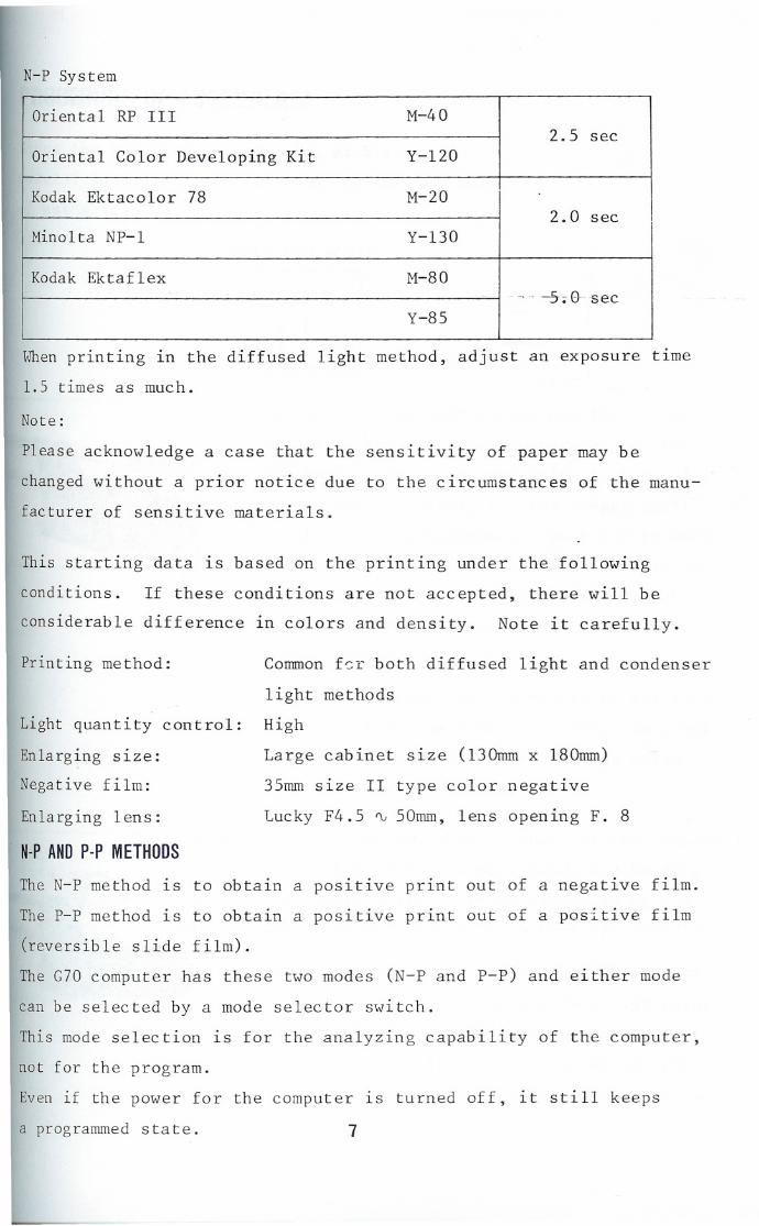
r-[
t!
~ N-P System
f
~t; "
Oriental RP III M-402.5 sec
Oriental Color Developing Kit Y-120
Kodak Ektacolor 78 M-202.0 sec
Mino 1ta NP-l Y-130
Kodak Ektaflex M-80- -, -- --5-~0- sec
Y-85
When printing in the diffused light method, adjust an exposure time
1. 5 times as much.
Note:
Please acknowledge a case that the sensitivity of paper may be
changed without a prior notice due to the circumstances of the manu-
facturer of sensitive materials.
This starting data is based on the printing under the following
conditions. If these conditions are not accepted, there will be
considerable difference in colors and density. Note it carefully.
Printing method: Common f~r both diffused light and condenser
light methods
HighLight quantity control:
Enlarging size:
Negative film:
Enlarging lens:
Large cabinet size (13Omm x l80mrn)
35mm size II type color negative
Lucky F4.5 ~ 50mrn, lens opening F. 8
N.P AND p.p METHODS
The N-P method is to obtain a positive print out of a negative film.
The P-P method is to obtain a positive print out of a positive film
(reversible slide film).
The G70 computer has these two modes (N-P and p-p) and either mode
can be selected by a mode selector switch.
This mode selection is for the analyzing capability of the computer,
not for the program.
Even if the power for the computer is turned off, it still keeps
a programmed state. 7

,nOCEDUREOFASSEMBLAGE
Since the enlarger is precision machine, be
careful in handling it according to the procedure
\0,fassemb 1age.
TOOLS AND SOL TS
cg:--~hexagonalwrenchkey 1 spanner
II --....hexagon socket headed bolts colomn fastening bolt
1. Position the upright column and the column
socket as shown in the photograph, set two
6mrnhexagon socket headed bolts in the holes
of the column socket, fit the longer shaft
of the attached hexagonal wrench key to each
bolt head, and tighten the bolts by turning
the shorter shaft of the hexagonal wrench
key clockwise until the bolts cannot be
turned by hand.
Note: Do not make use of pliers or the like
to turn the hexagonal wrench key, but
be sure to drive both of the bolts
evenly by fingers.
2. Then, insert the shorter shaft of the hexagonal
wrench key into each bolt head, and holding
its longer shaft, turn it clockwise by 1/4
turn. Do not turn it more than 1/4 turn.
Note: Be sure to fasten the upright column
by even force since uneven tightening
of two bolts will unfavorably affect
the parallelism between the upright
column and the column socket.
8

3. Insert the column fastening bolt from the
rear side of the baseboard, and fasten the
column socket on the baseboard. Position
the upright column with the scale on the
column turned toward the front side as
shown in the p~otograph. Tighten the column
fastening bolt sufficiently with the attached
spanner.
4. Hold the light box with the cap on the upside
and insert it into the body with the mark,
"Condenser System" or "Diffusion System",
of the light box positioned as shown in the
photograph.
Note: Set the light box gently with care
so that a shock may not be given to
it.
5. Remove two filter unit set screws indicated
by the arrow heads in the photograph, and
take the filter unit out of the body.
6. Insert the halogen lamp bulb into the socket
in the unit straight so that the edge of
lamp, shade may touch slightly on the bottom
of the uni t. If the bulb is inclined due
to the lamp base, adjust it by four screws
indicated by the arrow heads in the photo-
graph so that it is straight.
Note: Do not soil the bulb with fingers.
9

~
,
7. Fit the attached negative carrier to the
enlarger. Fasten up the cord from the filter
unit at the cord hook on the carriage.
8. Mount an enlarging lens (with the Leica
screw mount) on the lens board attached to
the enlarger.
Tighten the lens board fastening screw slightly
to fasten the lens board.
9. Connect a cord coming out of the back of the
base plate to the connector of the transformer.
Connect a cord coming out of the transformer
to the AC power source.
the transformer OFF.
Leave the switch of
10. Connect the cord plug of the exposure measure-
ment light sensor to the connector shown in
the photograph.
Wiring Panel on the Back of the Base Plate
110 @ ~$ r--
To transformer Filter unitcord
(;)
°00 0
000
INPUT
Exposure-measuring cord
10
If a AE foot switch interlockingplug is used, it interlocks withthe foot switch.

PROGRAM
COLORANALYSISPROGRAM(IT CANBEALSOCONDUCTEDIN A BRIGHTROOM.)
Ic~"" MI
~~.. Vi
1. Insert a standard negative into the enlarger.
Set the color head filter to the same con-
di tion as when the ref erence pr~int was
prepared. (Example: M60, Y90) Adjust the
enlargement lens to the same lens opening
(example:
print.
F8) as in case of the reference
The location of the bellows (light sensor)
should be positioned at the same focal as
in case of the reference print.
2. In case of the N-P method, turn the mode
selector switch to N-P.
case of the P-P method.
Turn it to P-P in
3. Press the focus switch to light up the
enlarger. Turn the M program knob to the
position where both LEDs of the color
analysis desplay "e~11" may be Iit 11p.
4. Turn the Y program knob so that both LEDs
of the color analysis display "e~Y" r;:2.y
be lit up.
11

.---I
5. If the four LEDs of the color analysis display
are all lit up, the program for the colorC~MC~Y
analysis of the reference print has been
completed.
For the case the program is changed after-
wards, note the scale values of the M and
. ~~L program knobs.
After having ended the program for the color
analysis, press the focus switch to light
off the enlarger.
EXPOSURETIME PROGRAM( IT SHOULDBE CONDUCTEDIN A DARKROOM.)
When the reference print is of a cabinet size
with the enlarging lens at F 8 and an exposure
of 3 seconds, and when a proper density is
obtained, program the display brightness and
exposure time of this state.
1. Confirm that the color head filter is set
to the same condition as when the reference
print was prepared. (Example: M60, Y90)
Adjust an enlargement size, focal point and
lens opening to the same condition as in
case of the reference print. Set timer
dial to 3 seconds (example) with the other
timer dials to O.
2. The G70 computer has three kinds of timers;
one with the unit of 10 seconds, another one
with the unit of 1 second and the last oneI .econ. the l..t one up to
. ,"cond.w[Lhout . o<ep. up to I second without a step. The exposure
time consists of the addition of these three
timer.
12

3. Darken a room and press the focus switch to
light up the enlarger. Put the exposure
measurement light sensor on the easel mask
and place the spot hole of the light sensor
on the brightest part of the projected
lmag e . (Both N-P and P-P methods)
In case of the N-P method, measure the light
on the shadowy part for the hair of a subject
or a landscape as shown in the photograph.
4. Turn the D program knob so that the red and
green LEDs of the light sensor may be lit
up. Adjust carefully because the programmlng
is done with an overexposure time when only
the red LED is lit up, and it is done with
an underexposure time when only green LED
is lit up.
The above-mentioned procedure has programmed
the density of the reference print.
Note down the scale value of the D program
knob and fit the cover. Then, turn off the
enlarger.
13

After having programmed, beautiful prints can
be obtained only by conducting the photometric
analysis of the projected image, if the film and
-printing system are of the same conditions as the
standard negative.
COLORANALYSIS(IT CANBEALSOCONDUCTEDIN A BRIGHTROOM.)
C"'" M
1. Insert a negative to be printed into the
negative carrier of the enlarger.
2. An analysis can be conducted more correctly
when the location of the same bellows (light
sensor) is positioned approximately to the
same position as when the reference print
was programmed.
3. Set the color head filter to the same value
as in case of the reference print. It is
because a correction value is to be close
to that for the reference print, even if
negatives are changed. It saves a trouble
of starting the filter from "Q".
4. Press the focus switch to light up the en-
larger. First, turn the color head M filter
knob and keep a balance so that both LEDs
of the color analysis display "C~ Mil may
be lit up.
14

5. Next, turn the Y filter knob and adjust a
balance so that both LEDs of the color
analysis display "C~Y" may be 1it up.
Ie. ...vi
6. The analysis display of the M filter tends
to be off-balanced due to the effect of the
Y filter. In that case, adjust the M filter
knob again to keep the balance of the color
analysis display "C""""'H".
7 . Thus, adjusting the M and Y filter knobs
by turns, repeat this step so that the fourC~MC~Y LEDs of the color analysis dispOlays tIC M
and C~Y" may be lit up with their balance
even. Every time the adjustment is repeated,
the balances of the four LEDs get closer.
8. If the four LEDs are lit up in the same
light quantity with the balances even, the
color analysis lS over. ~~en conducting all
exposures at the same time afterward, note
down the filter value and film number in
this state.
l.
3.
5.
7 .
9. Color balances OK
After having ended the color analysis,
press the focus switch once to light off
the enlarger.15
(M lit up) 2. Increase the scale of the M filter.
(C lit up) 4. Decrease the scale of the M filter.
(Y lit up 6. Increase the scale of the Y filter.
(C lit up) 8. Decrease the scale of the Y filter.

MEASUREMENTOFEXPOSURETIME (IT SHOULDBECONDUCTEDIN A DARKROOM.)
L--
1. Hhen printing the film on which all color
corrections were previously measured in a
bright room, insert the film into the en-
larger and set the enlarger to the M and Y
correction values which were previously
taken dmm.
Hhen printing the film immediately after
the color analysis, measure in the state
as it is because the correction filter and
film have been already set in the enlarger.
2. Press the focus switch and project onto the
easel mask. Adjust a focus and decide an
enlargement magnification and the composition
of the image.
Next, stop down the enlarging lens open1ng.
Although it is normally F 8, adjust it to
F 8 ~ 1 ~ 2 in accordance with the brightness
of the projected 1mage.
3. Put the exposure measurement light sensor
on the easel and shift its spot hole onto
the brightest part of the projected image.
16

4. Set the three timer dials to O. Turn the
l-second-unit dial gradually to the right
and search a position where the red and
green LEDs of the light sensor light up.
When only the green LED is lit up, a set
timer shows an underexposure, and when only
the red LED is lit up, it shows an over-
exposure.
5. When the red LED does not light up, even if
the 1-second-unit dial was fully turned to
the right, return the dial to the left and
set the 10-second-unit dial to 10 seconds
or more, and then turn the l-second-unit
dial to the right agaIn. Finally, perform
fine adjustment with the I-second step1ess
dial.
the enlarger. Insert photographic paper
into the easel mask and press the exposure
button. Thus, a measured exposure time can
be provided.
17
6. When the red and green LEDs are both lit up,
a proper exposure time has been set. Remove
the light sensor from the easel mask and
press the focus switch to turn light off

7. If exposed paper is developed, it comes out
as well as the reference print.
For the development, be sure to keep the
same conditions constantly as in case of the
reference print without fail. If a developer
and a time frequently change, it may cause
difference in the color balances and density.
Attention should be adequately paid to the
fatigue of the developer and supply additional
one, if necessary.
When printing monochrome with this equipment,
to "0" position, you can set each filter dial.
18