Embed Size (px)
DESCRIPTION
Test report for fugitive emission testing with various steps and calculation methods.
Citation preview
1 Scope This document specifies the fugitive emission testing procedures for evaluation of external leakage of valve stem seals and body joints of 1” ball valve supplied by Blaker Pumps. Tested valve shall be certified for fugitive emissions when all steps of this procedure have been satisfactory completed. As per the client’s instruction these valves shall be tested for following criteria:
i. Endurance Class: CO1 ii. Tightness Class: B iii. Test Temperature: 750C
2 References This procedure is prepared based on following international standard. ISO 15848-1 Classification system and qualification procedures for type testing of valve.
3 Safety Notes
� A full JSA of the system shall be carried out before starting the test. All potential hazards shall be identified and action shall be taken to eliminate these hazards.
� Hand gloves shall always be worn all times before handling the valve.
� The body of the test valve must be hydro tested prior to any fugitive emissions test as per the relevant standard.
4 Quality Notes
� Only a fully assembled valve shall be used for the test.
� The valve shall have been tested and accepted in accordance with ISO 5208 or any
other applicable standard and no subsequent protective coating shall have been
applied.
� The test valve interior shall be dried and lubricants (if any) shall be removed. The
valve and test equipment shall be clean and free of water, oil and dust.
� If a test valve is equipped with a manually adjustable stem (or shaft) seal(s), it shall
be initially adjusted according to the manufacturer instructions, and recorded in the
test report.
� The test fluid shall be helium gas of 97 % minimum purity. The same test fluid shall
be used throughout the test.
� The test temperature shall be recorded for each leakage measurement.
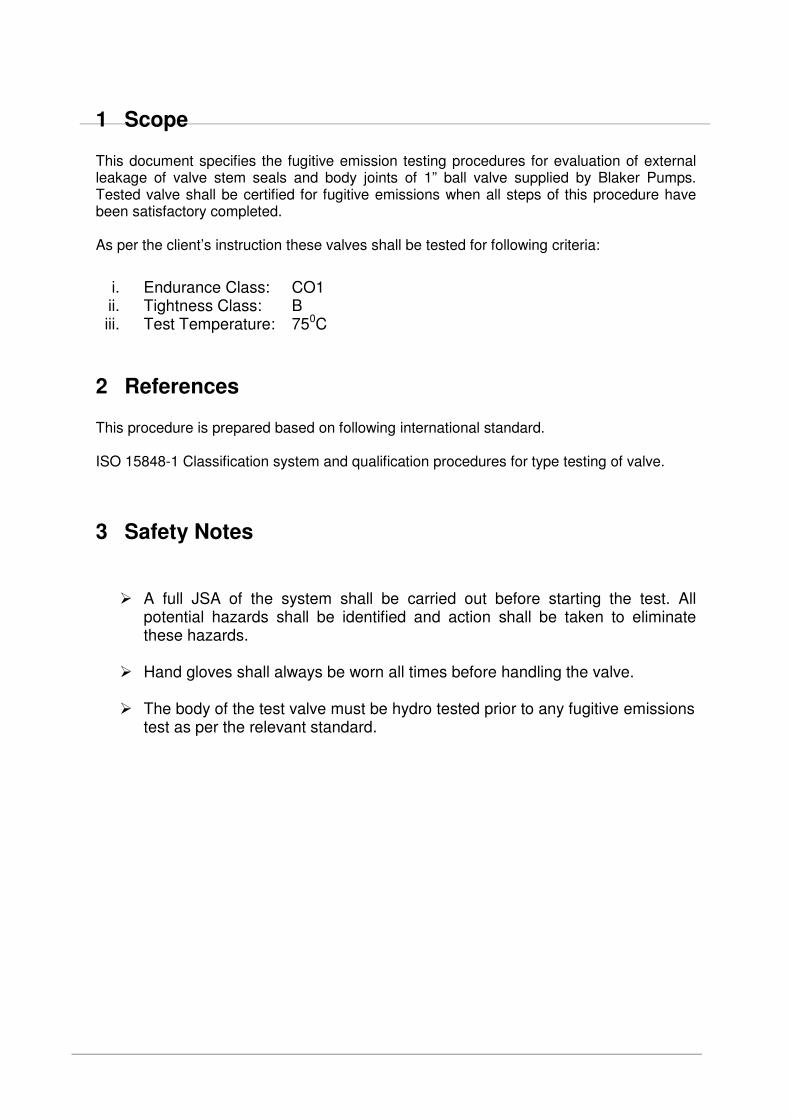
� The temperature of the test valve shall be measured at three locations (X, Y, Z), as
shown in Figure 1, and recorded in a test report. All temperatures at location X, Y
and Z shall be stabilized before leakage is measured. Variation of temperature shall
be within +5%.
1. Location X: Flow Path 2. Location Y: Valve Body 3. Location Z: Stuffing box
Figure 1 – Location for measurement of temperature
� Measurement at location "X" shall be used to determine the test temperature.
� Measurements at locations "Z" and “Y” are recorded for information only.
� (see Figure 1).
� Temperature at location "Z" shall be stabilized for minimum 10 min prior to leakage
measurement.
5 Equipment
� Source of 97% helium which can apply and maintain test pressure within +5% of the
nominal value.
� Hand lever or actuator to mechanically cycle the valve.
� Heating coil to heat the valve to the test temperature, and maintain it within +5% but
not exceeding 75C. Valve shall not be operated during temperature change.
� Data recorder to record time, pressure, temperature, leakage and duration of a valve
mechanical cycle.
� Torque wrench to measure the actuation torque of the valve.
� Standard capillary leak for calibration of mass spectrometer.
6 Preparation of Test
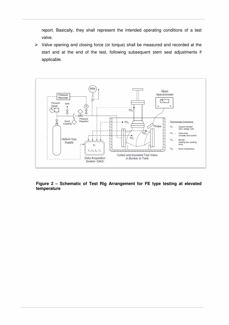
� The test valve shall be mounted on a test rig, according to the arrangement as shown
in Fig 2.
� All sealing systems shall have been properly adjusted beforehand, according to the
manufacturer's instructions. For valves using packings as a stem seal, the tightening
torque of the gland boltings shall be measured and recorded after any stem seal
adjustment. Mechanical adjustments of stem (or shaft) sealing system during the
type test shall be permitted only once for class CO1, if stem (or shaft) leakage has
been measured in excess of the target tightness class B.
� If a stem (or shaft) sealing arrangement fails to achieve the target tightness class, or
it is not possible to continue mechanical cycling, the test shall be considered
terminated, and the test valve shall be evaluated for qualification of lower tightness
and endurance classes, if applicable.
� Leakage from the stem (or shaft) seal and from the body seals shall be separately
measured. If the valve does not allow such a separate measurement the total
leakage of both stem (or shaft) and body seals shall be measured at the same time
according to Section 8 of this procedure.
� Actual methods of mechanical cycles shall be in accordance with the manufacturer's
instructions, and opening, closing and dwelling time shall be recorded in the test
report. Basically, they shall represent the intended operating conditions of a test
valve.
� Valve opening and closing force (or torque) shall be measured and recorded at the
start and at the end of the test, following subsequent stem seal adjustments if
applicable.
Figure 2 – Schematic of Test Rig Arrangement for FE type testing at elevated temperature
7 Test Procedure Sequence Template of test record table is recorded in Annex 3.
7.1 Measurement of valve torque before testing
� Record the valve operating torque in the test report.
7.2 Preliminary test at room temperature (test 1)
� Pressurize a test valve with the test fluid to the test pressure as specified Annex-1 of
this procedure.
� After the test pressure has been stabilized, measure leakages both from the flushing
chamber, in accordance with Section 8 of this procedure.
� Do not over pressurize the valve
� Record the test results (nominal and max leakage measurements) in the test report.
7.3 Mechanical cycle test at the room temperature (test 2)
� Perform 150 no. of mechanical cycles at room temperature while the test valve is
kept pressurized.
� Measure the leakage from the flushing chamber only, in accordance with Section 8 of
this procedure.
� Do not over pressurize the valve
� Record the test results (nominal and max leakage measurements) in the test report.
7.4 Static test at the selected test temperature (test 3)
� By heating the valve in the oven, increase the temperature of the valve to 750C.
� Pressurize the test valve with the test fluid to the test pressure as specified in Annex-
1 of this procedure the test temperature of 750C.
� After the test pressure has been stabilized at location X, adjust the valve temperature
to the selected test temperature, ensuring that the test pressure does not exceed the
level specified in Annex 1.
� Record test temperature at location X, Y, Z into test report.
� After the valve temperature has been stabilized with an allowance of +5% with a
maximum of 150C, measure the leakage from the flushing chamber only in
accordance with Section 8 of this procedure.
� Do not over pressurize the valve
� Record the test results (nominal and max leakage measurements) in the test report.
7.5 Mechanical cycle test at the selected test temperature (test 4)
� Perform 100 no. of mechanical cycles at the test temperature of 750C while the test
valve is kept pressurized.
� Measure the leakage from the flushing chamber only in accordance with Section 8 of
this procedure.
� Do not over pressurize the valve
� Record the test results (nominal and max leakage measurements) in the test report.
7.6 Intermediate static test at the room temperature (test 5)
� Allow a test valve to return to the room temperature, without artificial cooling.
� After the valve temperature has been stabilized, measure the leakage from the
flushing chamber only in accordance with Section 8 of this procedure.
� Do not over pressurize the valve
� Record the test results (nominal and max leakage measurements) in the test report.
7.7 Mechanical cycle test at the room temperature (test 2 – repeat)
� Repeat the test as per 7.2 of this procedure.
7.8 Static test at the selected test temperature (test 3 – repeat)
� Repeat the test as per 7.3 of this procedure.
7.9 Mechanical cycle test at the selected test temperature (test 4 – repeat)
� Repeat the test as per 7.4 of this procedure.
7.10 Final test at the room temperature (test 6)
� Allow a test valve to return to the room temperature, without artificial measures.
� After the valve temperature has been stabilized, measure the leakage from the
flushing chamber in accordance with Section 8 of this procedure.
� Record the test results (nominal and max leakage measurements) in the test report.
7.11 Measurement of valve torque after testing
� Record the valve operating torque in the test report.
7.12 Post-test examination
� After all the tests have been successfully completed, the test valve shall be
disassembled and all sealing components shall be visually examined to record
notable wear and any other significant observations for information.
7.13 Qualification
� Tested valves shall be qualified when all
I. steps of test procedures have been satisfactorily performed for the target
performance class;
II. All leakage measurements are verified equal or lower than the values specified in
Annex-2 of this procedure.
8 Stem seal leak measurement using Flushing method
This section specifies the use of a helium leak detector, fitted with a detector probe to
measure the concentration due to emissions from stem seals. The test medium shall be 97%
helium.
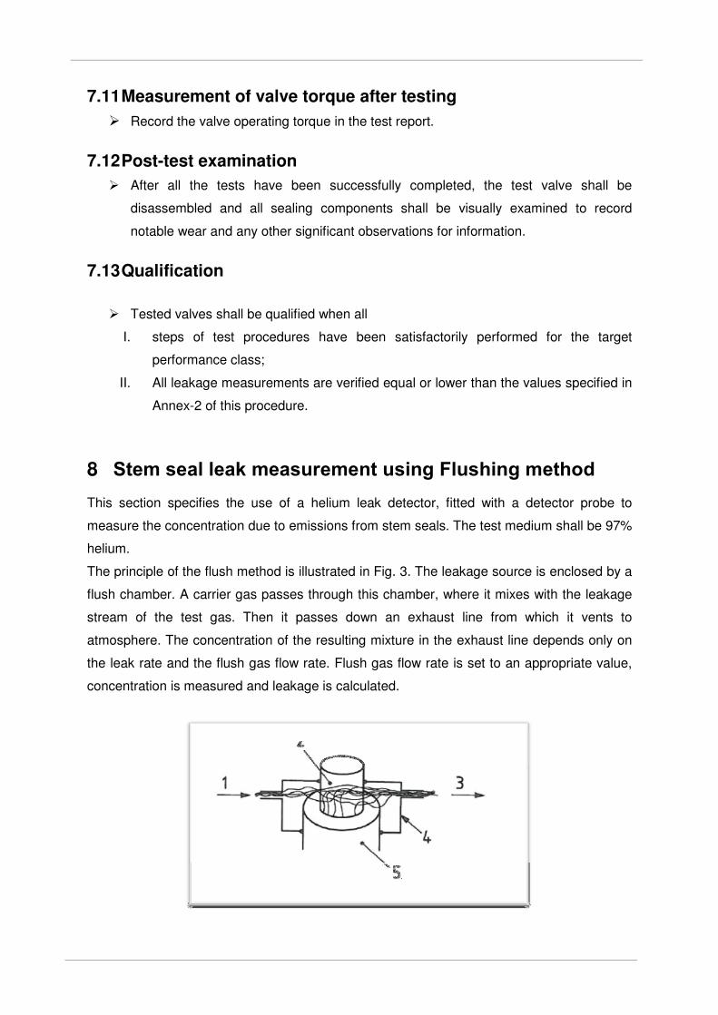
The principle of the flush method is illustrated in Fig. 3. The leakage source is enclosed by a
flush chamber. A carrier gas passes through this chamber, where it mixes with the leakage
stream of the test gas. Then it passes down an exhaust line from which it vents to
atmosphere. The concentration of the resulting mixture in the exhaust line depends only on
the leak rate and the flush gas flow rate. Flush gas flow rate is set to an appropriate value,
concentration is measured and leakage is calculated.
Figure 3 – Principle of flush method
The flush chamber may be devised from a rigid cover, from flexible material taped in place or
by making use of a suitable feature of the valve. The enclosed volume should be kept to the
minimum possible to minimise the time taken for a measurement to reach a steady value.
Equipment set up procedures (with flow rate detector):
1. Assemble and start up detector according to the manufacturer’s instructions and run
for an appropriate warm-up period.
2. If the detector has the facility of self-internal calibration function, use this function
according to manufacturer’s procedure.
3. Determination of probe flow rate. Connect the detector’s probe to the downstream
side of a calibrated flow meter. Leave the upstream side open to the atmosphere.
With the instrument running and warmed up, note the flow rate indicated on the flow
meter. Record Probe Flow Rate into test report.
4. Flush Gas Supply. Flush gas flow meter should be downstream of the pressure and
flow regulators. Pressure regulator situated upstream of the flow meter. Flush gas
flow rate can be adjusted by flow control valve. Record Flush Gas Flow Rate into test
report.
5. Set Up Diagram.
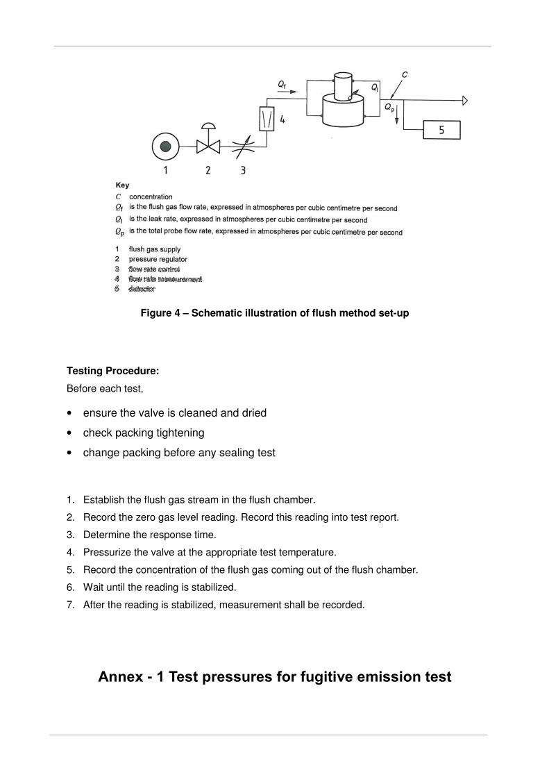
Figure 4 – Schematic illustration of flush method set-up
Testing Procedure:
Before each test,
• ensure the valve is cleaned and dried
• check packing tightening
• change packing before any sealing test
1. Establish the flush gas stream in the flush chamber.
2. Record the zero gas level reading. Record this reading into test report.
3. Determine the response time.
4. Pressurize the valve at the appropriate test temperature.
5. Record the concentration of the flush gas coming out of the flush chamber.
6. Wait until the reading is stabilized.
7. After the reading is stabilized, measurement shall be recorded.
Annex - 1 Test pressures for fugitive emission test
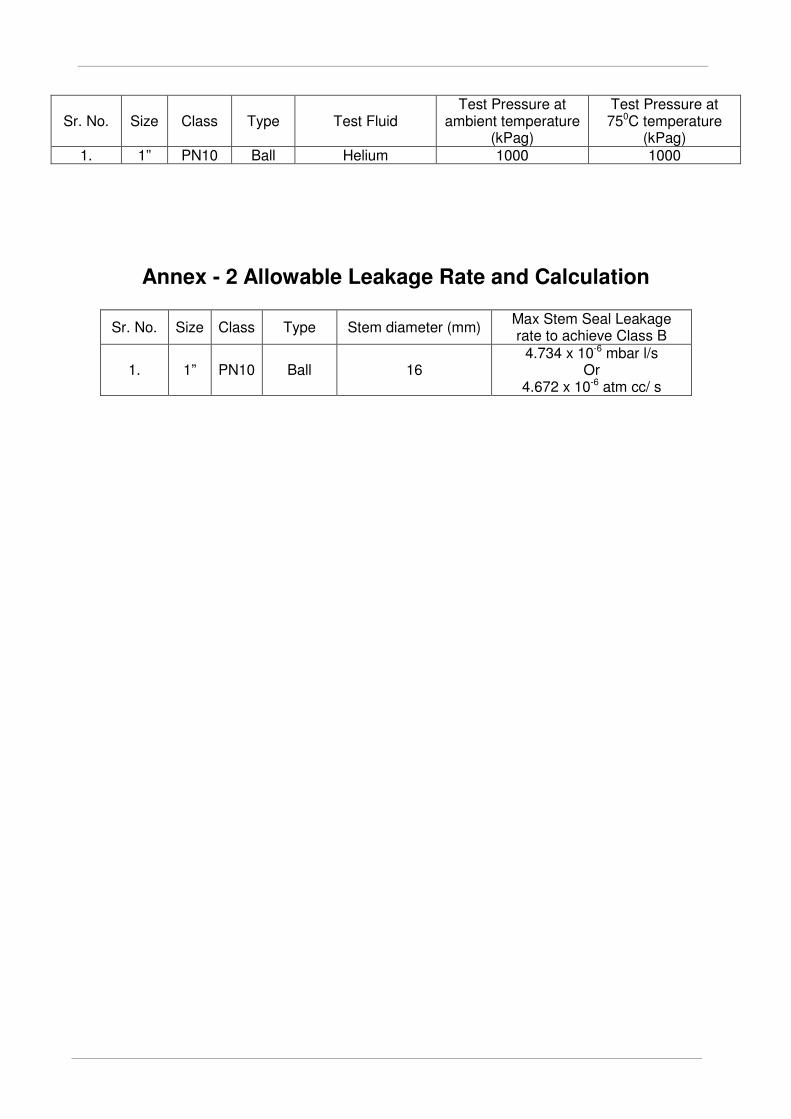
Sr. No. Size Class Type Test Fluid Test Pressure at
ambient temperature (kPag)
Test Pressure at 750C temperature
(kPag) 1. 1” PN10 Ball Helium 1000 1000
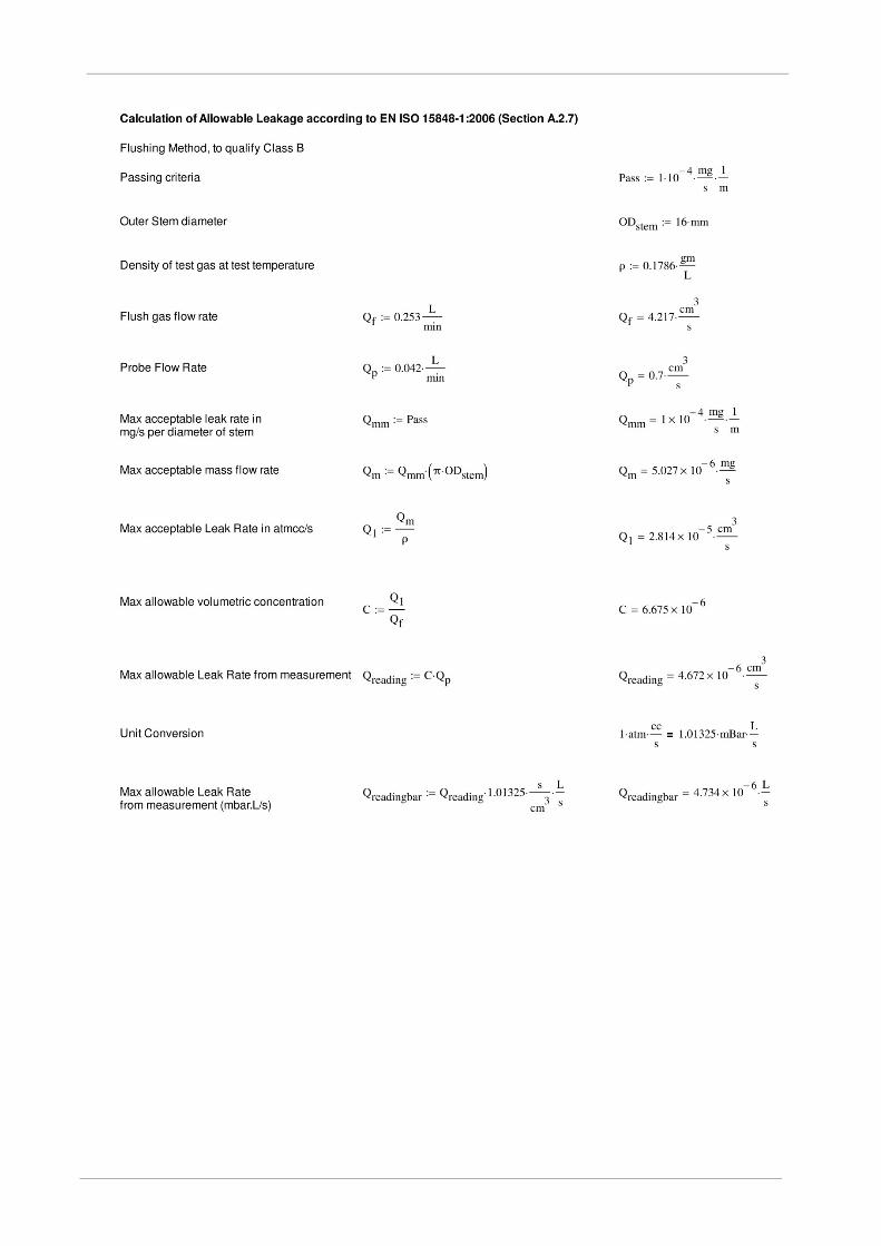
Annex - 2 Allowable Leakage Rate and Calculation
Sr. No. Size Class Type Stem diameter (mm) Max Stem Seal Leakage rate to achieve Class B
1. 1” PN10 Ball 16 4.734 x 10⁻⁶ mbar l/s
Or 4.672 x 10⁻⁶ atm cc/ s
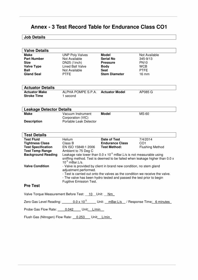
Annex - 3 Test Record Table for Endurance Class CO1
Job Details
Valve Details Make UNP Poly Valves Model Not Available Part Number Not Available Serial No 345-9/13 Size DN25 (1inch) Pressure PN10 Valve Type Lined Ball Valve Body WCB Ball Not Available Seat PTFE Gland Seal PTFE Stem Diameter 16 mm
Actuator Details Actuator Make ALPHA POMPE S.P.A. Actuator Model AP085 G Stroke Time 1 second
Leakage Detector Details Make Vacuum Instrument
Corporation (VIC) Model MS-60
Description Portable Leak Detector
Test Details Test Fluid Helium Date of Test 7/4/2014 Tightness Class Class B Endurance Class CO1 Test Specification EN ISO 15848:1 2006 Test Method: Flushing Method Test Temp Range Ambient to 75 Deg C Background Reading Leakage rate lower than 0.0 x 10
-5 mBar.L/s is not measurable using
sniffing method. Test is deemed to be failed when leakage higher than 0.0 x 10
-5 mBar.L/s.
Valve Condition - Valve is provided by client in brand new condition, no stem gland adjustment performed. - Test is carried out onto the valves as the condition we receive the valve. - The valve has been hydro tested and passed the test prior to begin Fugitive Emission Test.
Pre Test Valve Torque Measurement Before Test: __10__Unit: __Nm_ Zero Gas Level Reading: ______0.0 x 10
-5_____ Unit: __mBar.L/s__ / Response Time: _6 minutes_
Probe Gas Flow Rate: ____0.042____ Unit:__L/min__ Flush Gas (Nitrogen) Flow Rate: __0.253___ Unit:__L/min_
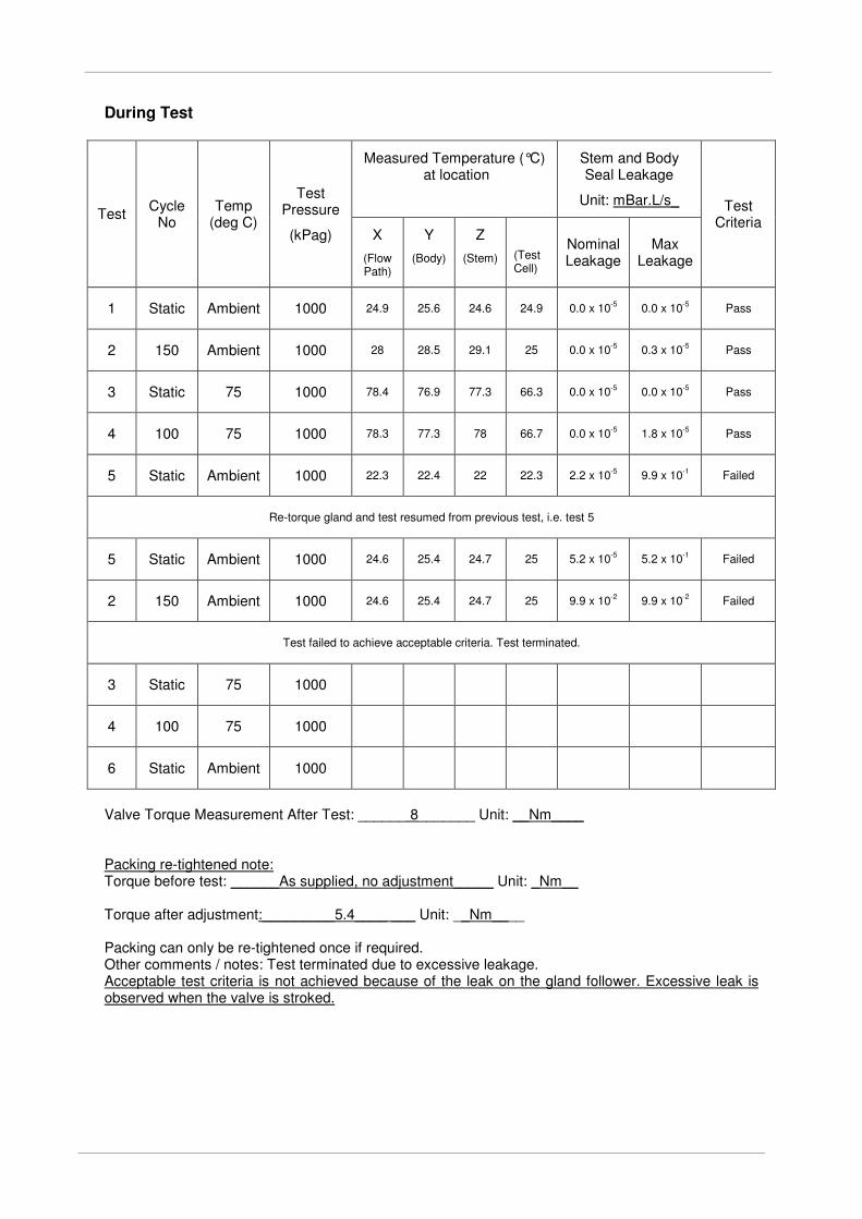
During Test
Test Cycle
No Temp
(deg C)
Test Pressure
(kPag)
Measured Temperature (°C) at location
Stem and Body Seal Leakage
Unit: mBar.L/s_ Test Criteria
X
(Flow Path)
Y
(Body)
Z
(Stem)
(Test Cell)
Nominal Leakage
Max Leakage
1 Static Ambient 1000 24.9 25.6 24.6 24.9 0.0 x 10⁻⁵ 0.0 x 10
-5 Pass
2 150 Ambient 1000 28 28.5 29.1 25 0.0 x 10⁻⁵ 0.3 x 10
-5 Pass
3 Static 75 1000 78.4 76.9 77.3 66.3 0.0 x 10⁻⁵ 0.0 x 10
-5 Pass
4 100 75 1000 78.3 77.3 78 66.7 0.0 x 10⁻⁵ 1.8 x 10
-5 Pass
5 Static Ambient 1000 22.3 22.4 22 22.3 2.2 x 10⁻⁵ 9.9 x 10
-1 Failed
Re-torque gland and test resumed from previous test, i.e. test 5
5 Static Ambient 1000 24.6 25.4 24.7 25 5.2 x 10⁻⁵ 5.2 x 10
-1 Failed
2 150 Ambient 1000 24.6 25.4 24.7 25 9.9 x 10⁻² 9.9 x 10
-2 Failed
Test failed to achieve acceptable criteria. Test terminated.
3 Static 75 1000
4 100 75 1000
6 Static Ambient 1000
Valve Torque Measurement After Test: ______ 8_______ Unit: __Nm____ Packing re-tightened note: Torque before test: ______As supplied, no adjustment_____ Unit: _Nm__ Torque after adjustment:_________5.4____ ___ Unit: __Nm____ Packing can only be re-tightened once if required. Other comments / notes: Test terminated due to excessive leakage. Acceptable test criteria is not achieved because of the leak on the gland follower. Excessive leak is observed when the valve is stroked.
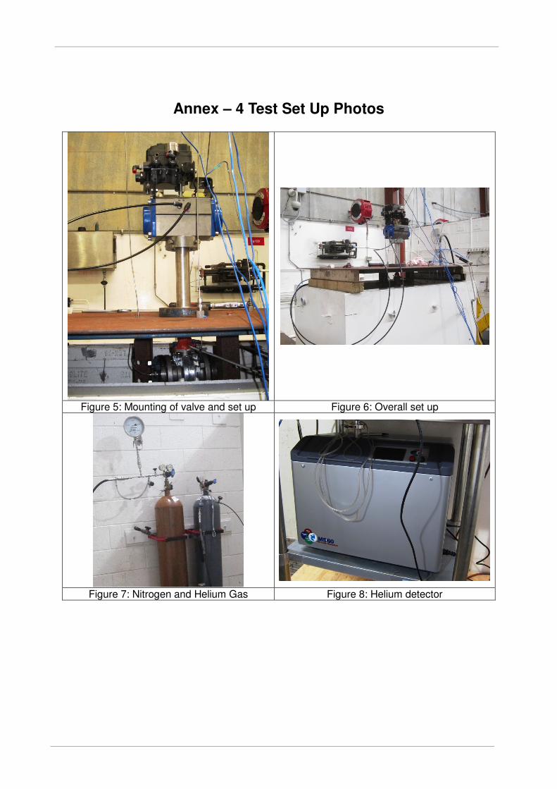
Annex – 4 Test Set Up Photos
Figure 5: Mounting of valve and set up Figure 6: Overall set up
Figure 7: Nitrogen and Helium Gas Figure 8: Helium detector
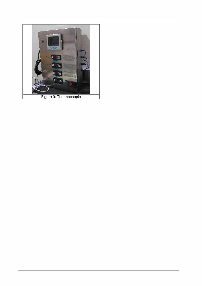
Figure 9: Thermocouple


![Fugitive Emission Frequently Asked Questions - … · Title: Microsoft Word - Fugitive Emissions - FAQ's_2014Feb19_draft3[3].docx Author: Freelance Station 2 Created Date: 2/20/2014](https://img.pdfslide.us/doc/110x75/5b33e0bf7f8b9a8b4b8b7d23/fugitive-emission-frequently-asked-questions-title-microsoft-word-fugitive.jpg)