Embed Size (px)
Citation preview
Fuel Spray Research on Light-Duty Injection Systems
Project ID ACE10
Christopher PowellAlan Kastengren, Jin Wang
2010 OVT Merit Review8 June 2010
Washington, DC
Team Leader: Gurpreet Singh
This presentation does not contain any proprietary, confidential, or otherwise restricted information
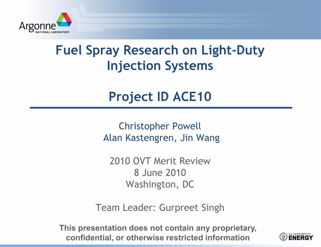
Overview
Project Start: FY2000
2
Timeline
Budget
Barriers
Partners
Lifetime Project Funding• $4M Since FY05
Recent Funding• FY2009: $645K• FY2010: $835K
Bosch, ERC Sandia, Delphi
“Inadequate understanding of the fundamentals of fuel injection”
“Inadequate capability to simulate this process”
“Inadequate understanding of fuel injector parameters (timing, spray type, orifice geometry, injection pressure, single-pulse vs. multi-pulse)”
These barriers impact:• Low-Temperature Combustion• Thermal Efficiency• System Cost
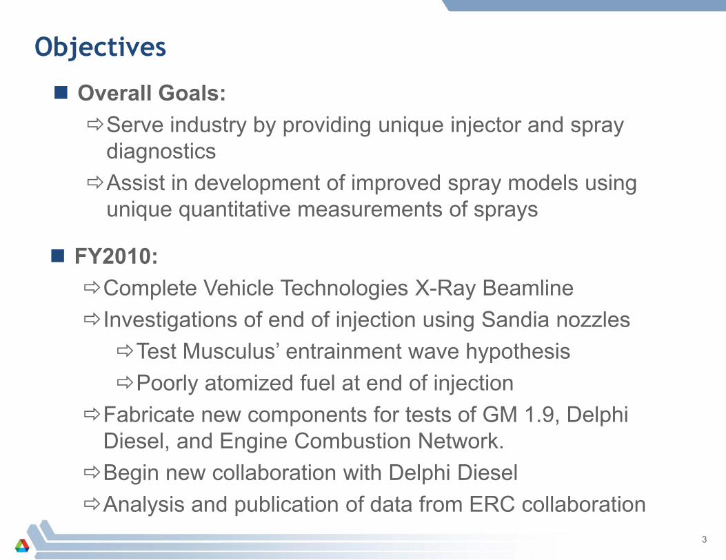
Objectives
3
Overall Goals:Serve industry by providing unique injector and spray
diagnosticsAssist in development of improved spray models using
unique quantitative measurements of sprays
FY2010:Complete Vehicle Technologies X-Ray BeamlineInvestigations of end of injection using Sandia nozzlesTest Musculus’ entrainment wave hypothesisPoorly atomized fuel at end of injection
Fabricate new components for tests of GM 1.9, Delphi Diesel, and Engine Combustion Network.
Begin new collaboration with Delphi DieselAnalysis and publication of data from ERC collaboration
Milestones, FY2009 and FY2010
4
Sep 2009: Measurements of End of Injection Effects June 2010: Complete fabrication of GM 1.9 fuel system July 2010: Measurements of GM 1.9 sprays Sep 2010: Measurements in support of Engine
Combustion Network
Sep 2010: Vehicle Technologies X-Ray Beamline opens to General User Proposals
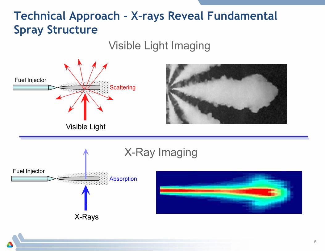
Technical Approach – X-rays Reveal Fundamental Spray Structure
5
Visible Light Imaging
X-Ray Imaging
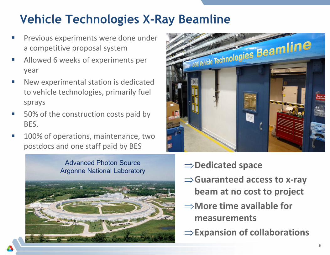
Vehicle Technologies X-Ray Beamline
6
Previous experiments were done under a competitive proposal system
Allowed 6 weeks of experiments per year
New experimental station is dedicated to vehicle technologies, primarily fuel sprays
50% of the construction costs paid by BES.
100% of operations, maintenance, two postdocs and one staff paid by BES
Advanced Photon SourceArgonne National Laboratory
⇒Dedicated space
⇒Guaranteed access to x-ray beam at no cost to project
⇒More time available for measurements
⇒Expansion of collaborations
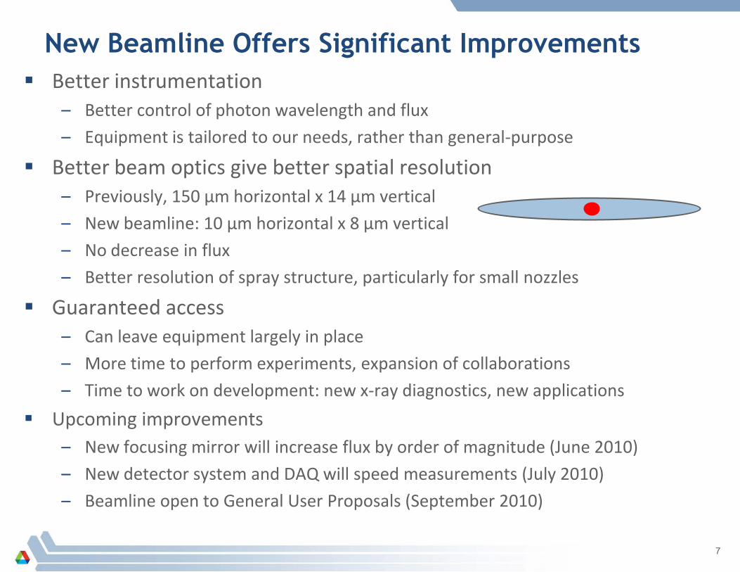
New Beamline Offers Significant Improvements Better instrumentation
– Better control of photon wavelength and flux
– Equipment is tailored to our needs, rather than general-purpose
Better beam optics give better spatial resolution– Previously, 150 µm horizontal x 14 µm vertical
– New beamline: 10 µm horizontal x 8 µm vertical
– No decrease in flux
– Better resolution of spray structure, particularly for small nozzles
Guaranteed access– Can leave equipment largely in place
– More time to perform experiments, expansion of collaborations
– Time to work on development: new x-ray diagnostics, new applications
Upcoming improvements– New focusing mirror will increase flux by order of magnitude (June 2010)
– New detector system and DAQ will speed measurements (July 2010)
– Beamline open to General User Proposals (September 2010)
7

Investigations of End of Injection Phenomena
Recent papers by Musculus et al. suggest very rapid mixing at end of injection
– “Entrainment Wave” travels downstream very quickly after EOI
– Can lead to overly lean mixtures and UHC’s
– Might be used to advantage
X-ray radiography can observe the end of injection without interference from fog of droplets
– Measure changes in density at EOI
– Measure propagation speed
Advanced Engine Combustion Working Group Meeting, February 20108
“Entrainment waves in decelerating transient turbulent jets”, M. P. B. Musculus, Journal of Fluid Mechanics 638, pp. 117-140, 2009.
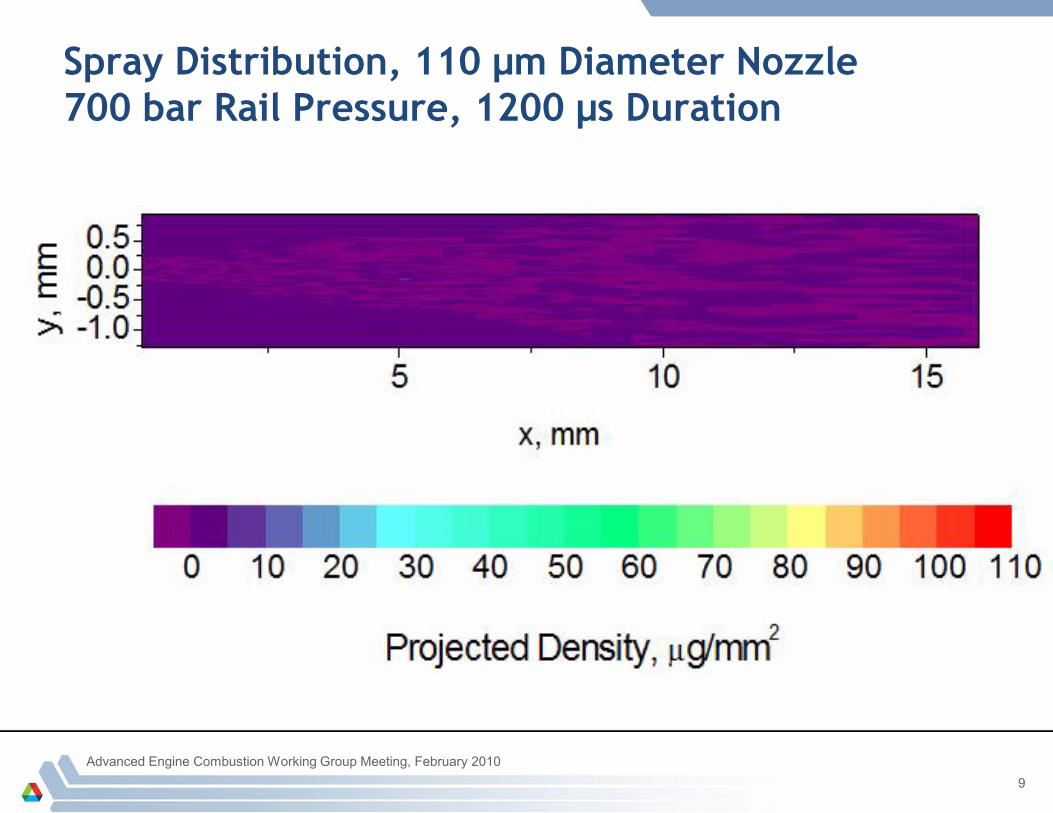
Spray Distribution, 110 µm Diameter Nozzle700 bar Rail Pressure, 1200 µs Duration
Advanced Engine Combustion Working Group Meeting, February 20109
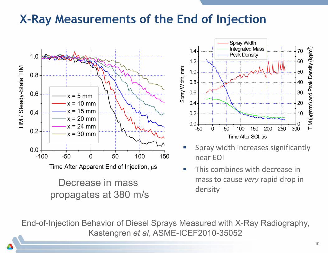
X-Ray Measurements of the End of Injection
10
End-of-Injection Behavior of Diesel Sprays Measured with X-Ray Radiography, Kastengren et al, ASME-ICEF2010-35052
Decrease in mass propagates at 380 m/s
Spray width increases significantly near EOI
This combines with decrease in mass to cause very rapid drop in density
-50 0 50 100 150 200 250 3000.0
0.2
0.4
0.6
0.8
1.0
1.2
1.4
0
10
20
30
40
50
60
70 Spray Width Integrated Mass Peak Density
Spra
y W
idth
, mm
Time After SOI, µs
TIM
(µg/
mm
) and
Pea
k De
nsity
(kg/
m3 )
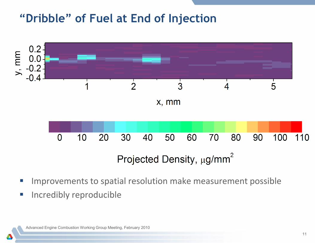
“Dribble” of Fuel at End of Injection
Improvements to spatial resolution make measurement possible
Incredibly reproducible
Advanced Engine Combustion Working Group Meeting, February 201011

Tracking Fuel Parcels After End of Injection
12
Parcels can be tracked to measure their speed
Density can be used to calculate their size: All are approximately equal to nozzle diameter
Rate of deceleration will depend on motion of ambient gas
– Consistent with stagnant environment
These parcels are important! Likely to contribute to soot or UHC’s
UHC’s are a target for tighter regulation
Source of these parcels:
Emptying of sac?
Needle bounce?
0.0 0.2 0.4 0.6 0.8 1.0 1.2 1.40
2
4
6
8
10 First Dribble Second Dribble Third Dribble
Peak
Pos
ition,
mm
Time After EOI, ms
0.0 0.1 0.2 0.3 0.4 0.50
1
2
3
4
5
6
7 Measurement Calculation
Peak
Pos
ition,
mm
Time After EOI, ms
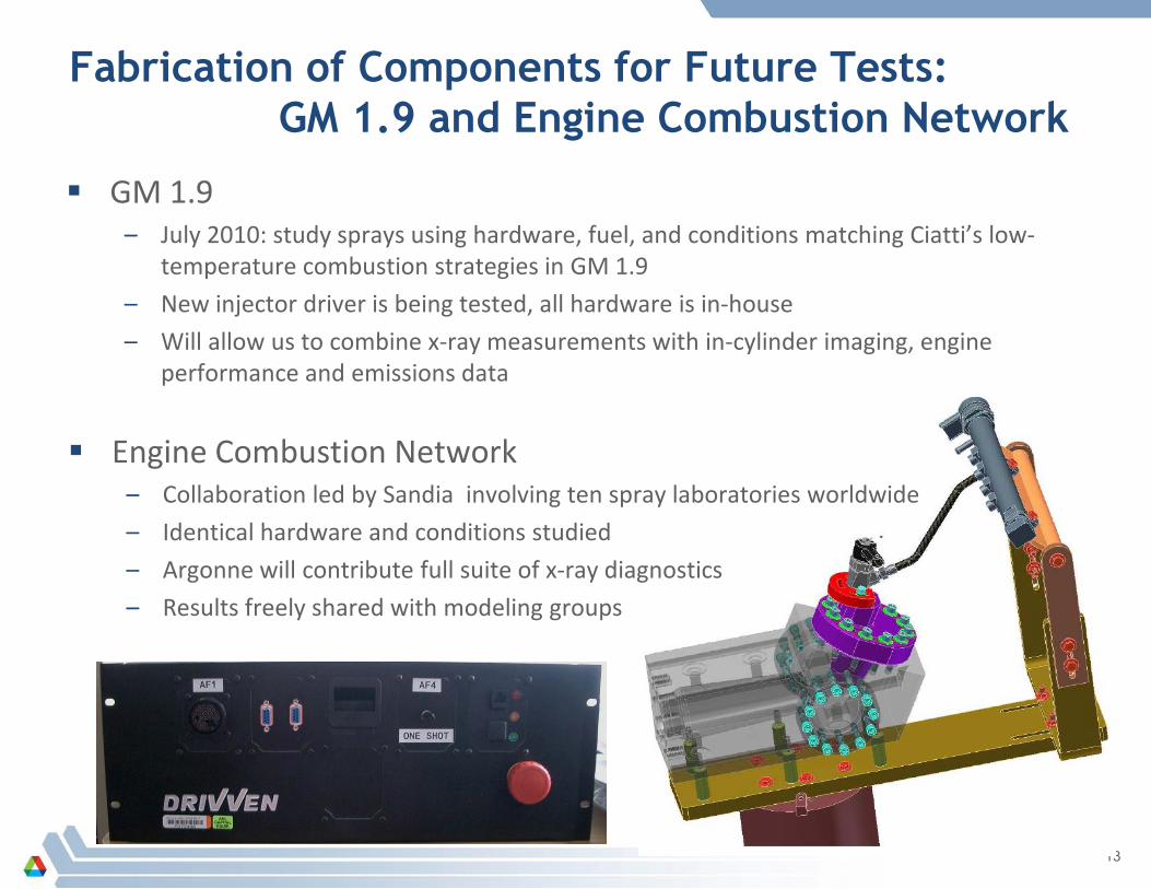
Fabrication of Components for Future Tests: GM 1.9 and Engine Combustion Network
GM 1.9– July 2010: study sprays using hardware, fuel, and conditions matching Ciatti’s low-
temperature combustion strategies in GM 1.9
– New injector driver is being tested, all hardware is in-house
– Will allow us to combine x-ray measurements with in-cylinder imaging, engine performance and emissions data
13
Engine Combustion Network– Collaboration led by Sandia involving ten spray laboratories worldwide
– Identical hardware and conditions studied
– Argonne will contribute full suite of x-ray diagnostics
– Results freely shared with modeling groups
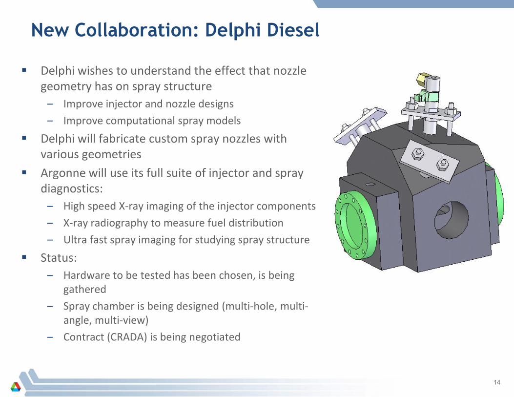
New Collaboration: Delphi Diesel
Delphi wishes to understand the effect that nozzle geometry has on spray structure
– Improve injector and nozzle designs
– Improve computational spray models
Delphi will fabricate custom spray nozzles with various geometries
Argonne will use its full suite of injector and spray diagnostics:
– High speed X-ray imaging of the injector components
– X-ray radiography to measure fuel distribution
– Ultra fast spray imaging for studying spray structure
Status:– Hardware to be tested has been chosen, is being
gathered
– Spray chamber is being designed (multi-hole, multi-angle, multi-view)
– Contract (CRADA) is being negotiated
14
15
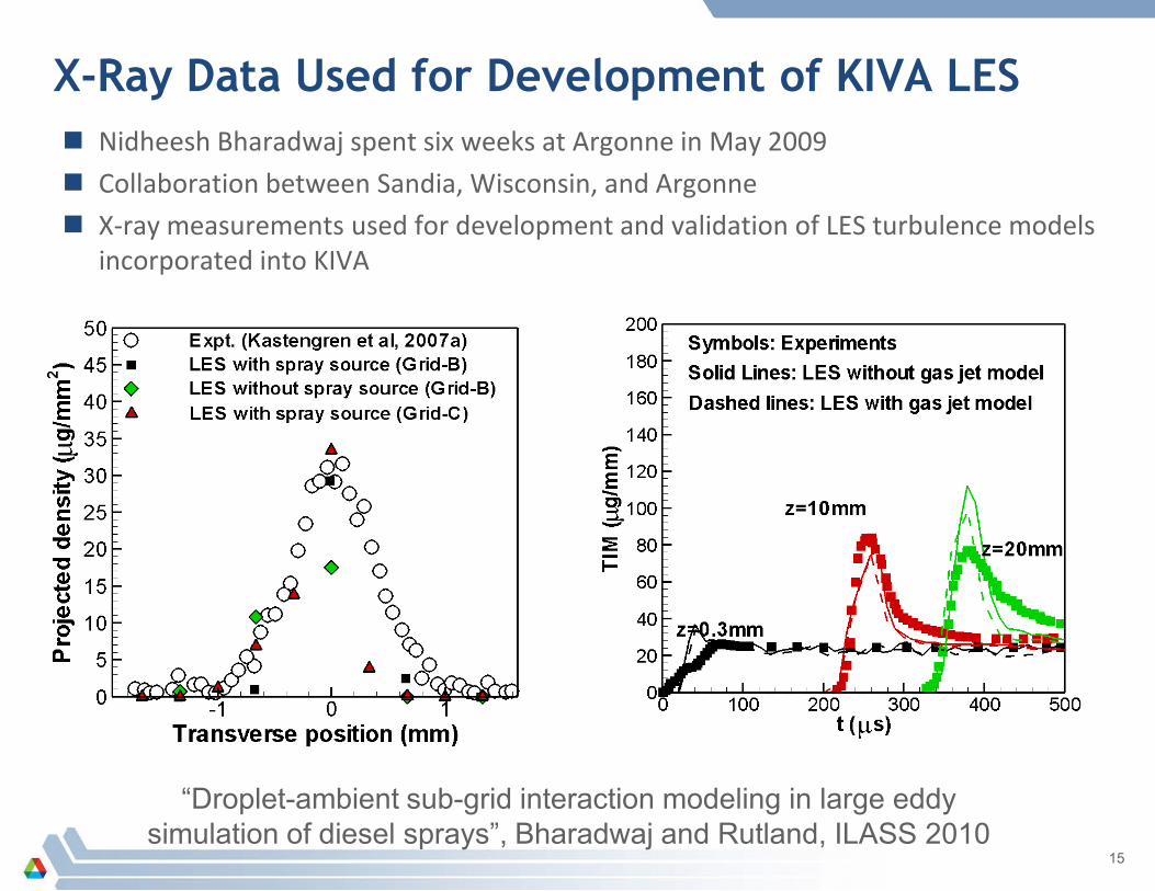
“Droplet-ambient sub-grid interaction modeling in large eddy simulation of diesel sprays”, Bharadwaj and Rutland, ILASS 2010
X-Ray Data Used for Development of KIVA LES Nidheesh Bharadwaj spent six weeks at Argonne in May 2009
Collaboration between Sandia, Wisconsin, and Argonne
X-ray measurements used for development and validation of LES turbulence models incorporated into KIVA
Collaboration and Coordination with Other Institutions
University of Wisconsin Engine Research Center– Joint measurements, used x-ray data for modeling, publication
Sandia National Laboratory– Measurements of their nozzles, comparison with combustion
chamber data
– Upcoming work with Engine Combustion Network
Delphi Diesel– New collaboration this year, currently negotiating CRADA
Chrysler– New collaboration later this year
– Funded by ARRA
– Statement of Work is complete, Chrysler currently negotiating with DOE
16
Future Work in FY2010 and FY2011 Strengthen ties between spray experiments and engine experiments
– Measurements supporting Argonne’s work on GM 1.9 – Match hardware, fuel, engine conditions– Comprehensive view of sprays, combustion, engine performance
Experiments supporting Sandia’s Engine Combustion Network– Argonne will provide x-ray measurements of spray and needle motion– Data will be provided to all partners, including spray modelers
Projects with industrial partners– Delphi Diesel– Chrysler
Studies of fuel additive effects– To date, cerium additive was required for measurements– With increased x-ray flux, can we reduce or eliminate additive?
New multi-pixel detector system– Collaboration between Argonne and Fermilab detector groups– Currently being designed to our specifications– 100% of cost paid by BES– Will speed measurements, improve spatial resolution
17
X-Ray diagnostics are being used to address a range of research challenges– Studying sprays under engine-relevant conditions
– Providing data for srpay model development and validation
– Understanding the fundamentals of atomization
– Provide a diagnostic for industrial partners
New experiment station dedicated to our research will make these measurements easier and available to a wider group of collaborators
18
Summary