Embed Size (px)
Citation preview

Fuel Gas SystemsNatural GasNatural Gas
PropanePropane
ButaneButaneBy: Ron George, CPD, President
President, Ron George Design & Consulting Services3525 N. Dixie Hwy., Monroe, MIMonroe, Michigan 48162Ph: (734) 322-0225 Cell: (734) 755-1908
ASPE/ASSE Meeting February 10, 2010Cleveland, OH

Fuel Gas Codes & Standards Mechanical Codes covering Fuel Gasses:Mechanical Codes covering Fuel Gasses: BOCA - Basic Mechanical Code (no longer updated in favor of
The International Codes) IAPMO - Uniform Plumbing Code (UPC) (Coordinated with
NFPA 54) IMC - International Mechanical Code (Prior to 2000) IFGC - International Fuel Gas Code (Fuel gas sections from
IMC were used to develop IFGC in 2000. Standards/Organizations dealing with Fuel Gas:Standards/Organizations dealing with Fuel Gas: AGA - American Gas Association NFPA 54 - National Fire Protection Association CSA - Canadian Standards Association ASME - Power & Process Piping Standards

How do I Size Gas Piping?How do I Size Gas Piping?
Determine the heating and equipment loads in BTU’s, convert to CFH and size the piping based on acceptable pressure drops using the appropriate code approved pipe material.
Equipment Label
CFH Distance Pipe Size ChartBTU/H

What does What does BTU BTU stand for?stand for?
BTU stands for “British Thermal Unit”.
A British Thermal Unit is the amount of heat required to raise one pound of water one degree Fahrenheit.

British Thermal Unit British Thermal Unit (BTU)(BTU)
1 pound of 61 degree water
1 BTU1 BTU
One pound ofOne pound of water water will increase by 1 will increase by 1 degree F when 1 BTU degree F when 1 BTU is added.is added.
Example: One pound of 60 degree F60 degree F water plus 1 BTU = one pound of 61 degrees F61 degrees F water.
1 pound of 60 degree water

What is What is CFHCFH??
CFH is an industry term used to describe the quantity of gas in Cubic Feet delivered during a specified time period. (Usually 1 hour)
So CFH stands for Cubic Feet per Hour.
1 Cubic foot of gas = 1000 BTUs + - (950-1100 BTUs/CF depending on the supplier)

Natural GasNatural Gas Properties Properties
Heat of combustion is measured in BTU’s/cu.ft. Natural Gas = 1,000 1,000 BTU’s/CF (Caloric Value)
Specific Gravity of Nat. Gas = .60 - .65.60 - .65 (Air =1.00)– Natural Gas is Lighter than air. (It will dissipate)
Flammability Limits (% Volume in air) – Lower = 3.9%, <<<<< Flame >>>>> Upper = 15.0%
Below 3.9% too lean for Combustion 9-10% = Good Above 15% too rich for combustion
Combustion air requirements in Cubic Feet: – Per cu. foot of Natural Gas = 10 cubic feet of air. – Per 100 BTU’s = 1 cubic foot of air.
1 Cubic Foot of Natural Gas = 1,000 BTU’s

Fuel Gas Properties Table:Fuel Gas Properties Table:
Source: NFPA 54 Handbook
Odor Additives

Fuel Gas is Explosive!Fuel Gas is Explosive!
Fuel Gas is Explosive!Fuel Gas is Explosive!

Fuel Gas is Explosive!Fuel Gas is Explosive!

Fuel Gas is Explosive!Fuel Gas is Explosive!
On May 19, 2008 a natural gas leak caused an explosion that injured 14 construction workers and damaged four floors on the unfinished hotel.

Fuel Gas is Explosive!Fuel Gas is Explosive!

Fuel Gas is Explosive!Fuel Gas is Explosive!
New Braunfels, TX. 1 dead, 1 seriously burned.

Three Pressure Classifications– High Pressure High Pressure (1,000’s PSI to 100’s)
– Medium Pressure Medium Pressure (5 PSI to 100’s PSI)
– Low Pressure Low Pressure (Less Than 5 PSI)
Natural GasNatural Gas Distribution Pressures Distribution Pressures
High Pressure gas is in typically only utilized in utility distribution lines, so
most plumbing engineers will deal with only MediumMedium or Low PressureLow Pressure Gas

Natural GasNatural Gas High Pressure High Pressure High Pressure - 1,000’s to 100’s PSI
– Transmission mains from pumping stations to Local Transmission mains from pumping stations to Local utility distribution mains. utility distribution mains.
– Typically High Pressures are utilized over long Typically High Pressures are utilized over long distances to reduce pipe sizes.distances to reduce pipe sizes.
Low press. High press. 900 psi+- High press. 900 psi+- Energy Company linesEnergy Company lines
Medium press. 60 psi +-PRV
PRV
1/2 psi +-
Pumping Station
Well

Natural GasNatural Gas Medium Pressure Medium Pressure
Medium PressureMedium Pressure – Local Utility DistributionLocal Utility Distribution– Large Industrial users.Large Industrial users.– Typically 5psi to 100’s of PSITypically 5psi to 100’s of PSI
Low press. High press. 900 psi +-
Medium press. Medium press. 60 psi +-60 psi +-PRV
PRV
1/2 psi +-
Pumping Station
Well
Local Gas Utility Co. Distribution linesLocal Gas Utility Co. Distribution lines

Natural GasNatural Gas Low Pressure Low Pressure
Low PressureLow Pressure – Commonly used inside buildingsCommonly used inside buildings– Commercial and residential users.Commercial and residential users.– Typically less than 5 PSI Typically less than 5 PSI (code requirement indoors)(code requirement indoors)
Low press.Low press. High press. 900 psi +-
Medium press. 60 psi +-PRV
PRV
1/2 psi + - 1/2 psi + -
Pumping Station
furnace
Homeowner ResponsibilityHomeowner Responsibility

Fuel GasFuel Gas Pressure ConversionsPressure Conversions
1 PSI1 PSI = = 2.31 feet of head 2.31 feet of head = = 28 inches of Water Column (WC)28 inches of Water Column (WC)
1 PSI1 PSI = = 16 Ounces 16 Ounces == 28 Inches 28 Inches == 2.31 feet of head2.31 feet of head
1/2 PSI1/2 PSI = = 8 Ounces8 Ounces = = 14 Inches WC 14 Inches WC == 1.16 feet of head1.16 feet of head
1/3 PSI1/3 PSI = = 6 Ounces6 Ounces = = 10 Inches WC 10 Inches WC == .77 feet of head.77 feet of head
1/4 PSI1/4 PSI = = 4 Ounces4 Ounces = = 7 Inches WC 7 Inches WC == .58 feet of head.58 feet of head
Gas pressures in buildings are often given in PoundsPounds, OuncesOunces or InchesInches. Make sure you convert to the proper units for sizing.
Often a manufacturer refers to equipment pressure in inches or ounces of pressure because it is a more accurate measurement.
Gas Pressure Conversion Chart

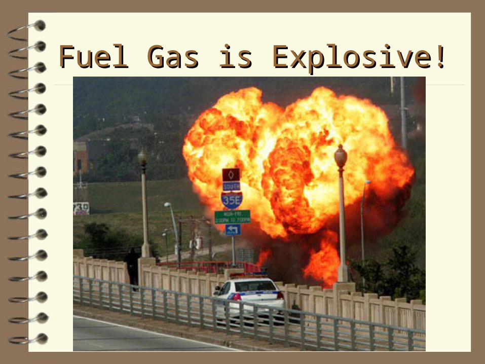
How Do we Change from a High How Do we Change from a High Pressure to a Low Pressure?Pressure to a Low Pressure? Pressure Regulators.

Gas Regulator Operation
1/2 PSI1/2 PSI½ PSI½ PSI
60 PSI60 PSI

Odor Added to Fuel GasOdor Added to Fuel Gas
The physical properties of natural gas include color, odor, and flammability. The principal ingredient of gas is methane, which is colorless, odorless, and highly flammable. Some of the associated gases in natural gas include Mercaptin, a hydrogen sulfide additive, it has a distinct and penetrating sulfur or Rotten EggRotten Egg odor, and a few parts per million is sufficient to impart a decided odor in the gas.A Volcanic Problem - The engineers for the Mirage Casino in Las Vegas needed to use Natural Gas to enhance the special effects for the volcano eruption in front of the casino. The concern was prior to eruption a distinctive odor of of Natural Gas or the sulfury Rotten EggRotten Egg smell would be noticeable to the crowds if gas with Mercaptin was used. The officials insisted on having some kind of odor so they could detect a gas leak. The engineers designed a scrubber to remove the Mercaptin odor and replace it with a Pina’ ColadaPina’ Colada odor.
Odor is added by most gas companies so leaks can be detected.

Natural GasNatural Gas Pipe Material Pipe Material Cast Iron Not recommended/allowed on fuel gas piping systems. Older cities used CI (½ PSI limit)
Black Steel (Schedule 40) ASME B36.10, 10M or ASTM A53 or ASTM A106
Polyethylene (PE) Underground outside building where approved)
Stainless Steel (CSST) ANSI/AGA LC 1.
Copper (Not recommended if gas is more than 0.3 Grains of Hydrogen Sulfide/100 CF) Often used as semi rigid tubing for appliance connections.
Aluminum ASTM B241 (Alum. Alloy 5456 is Prohibited)
(All piping material selections should meet the local code’s approved materials list.)
Abv. ground PE or asphalt wrapped Sch 80 - 160 Black steel W/ Cathodic Protection (Pressure often dictates material)
wrapped & coated Black Steel U.G.PRV
PRV
CSSTPumping Station
furnace
Copper orPolyethylene or
Black Steel/CSST

Corrugated Stainless Steel Tubing (CSST)Corrugated Stainless Steel Tubing (CSST)
CSST has made residential and light commercial gas-distribution much easier. Black steel pipe is still preferred for mains and trunks to manifolds. From the manifold the branch piping can be installed with ease.
CSST is lightweight and flexible and will cut down on installation time up to 50%.

Underground Underground Gas Piping InstallationsGas Piping Installations
Clearances - Far enough from U.G. structures to avoid contact and provide protection against damage. U.G. plastic piping shall be clear of or insulated from heat sources. (U.G. Steam mains, Htg HW pipes Etc.)
Protection Against Damage - Unstable soil, Foundation Walls, Heavy vehicles: Provide sufficient depth of cover or a pipe sleeve.
When gas piping is buried in planting areas, bury piping sufficiently below cultivating depth.
Warning Tape/Wire - Always put a tracer wire with plastic piping and bury “WARNING BURIED GAS LINE” tape in trench above all gas piping to warn excavators of pipe below.

Protection Against DamageProtection Against Damage
Provide sufficient depth of cover or a pipe sleeve where there is unstable soil, a foundation wall penetration or heavy vehicle traffic.
When gas piping is buried in planting areas, bury piping sufficiently below cultivating depth.
G

Warning Tape/Tracer WireWarning Tape/Tracer Wire Engineers should always require a tracer wire when using plastic piping
to allow pipe locators to find the pipes. Also specify warning tape that states: “WARNING BURIED GAS LINE
BELOW”. The tape should be in the trench at least 12 inches above the gas piping to warn excavators of the gas pipe below
Caution - Buried Gas Line
(In trench 12”above pipe)
Caution - Buried Gas Line
Tracer Wire (In trench above plastic pipe)
Buried Gas Line
Warning Tape

Underground Underground Gas Piping InstallationsGas Piping Installations
Cover Depth - Should be installed with at least 18 inches of cover. Can be 12 inches in areas where external damage is not likely. If less than 12 inches provide a protective conduit or bridging. Always use warning tape. & tracer wire for plastic piping.
Backfilling Trenches - Pipe should have a firm, continuos bearing on trench bottom. When installing gas piping, especially plastic, in a flooded trench care should be exercised to prevent the pipe from floating up in the
trench during backfilling operations.
Tracer Wire (for plastic pipe)
Gas PipeContinuous pipe bedding
Caution Tape

Underground Underground Gas Piping InstallationsGas Piping Installations
Protect Against Corrosion - Ferrous metal piping that is in contact with earth should be protected from corrosion by asphalt coating and wrapping piping below grade.
Protect Against Freezing - If the fuel gas supplier indicates, hydrates or moisture is high, the gas piping should be protected from freezing. Freezing of water in drip legs or low points in the piping can split piping and lead to gas leaks and possibly and explosion or fire.
Wet gas condenses water to this point
Boomallowing gas to leak out of pipe
Freezing can crack pipe
Locate Gas line below frost line or in a heated space.
If Gas line is subject to freezing provide heat tracing and Insulation.

Dirt Leg Dirt Leg (For Dry Gas)(For Dry Gas)
Sediment falls
Clean Gas
Source: NFPA 54
Handbook

Emergency Gas Shut-off Valve (Earthquake valve)Emergency Gas Shut-off Valve (Earthquake valve)
Some seismic areas of the country require an Emergency Gas shut-off valve that automatically closes when there is an earthquake.
The Earthquake Valve Industry has emerged because of the recent earthquakes and ensuing fires that have struck California and other parts of the world. Designers, Building Officials and Utility companies have become aware of the need for Earth Quake
Valves (EQVs) after experiencing and viewing these disasters.
Source: Safe-T-Quake Co.

Gas Pipe through Foundation Wall Below Gas Pipe through Foundation Wall Below Grade not allowed in most areas!Grade not allowed in most areas!
Piping through foundation walls below grade should have a sleeve with the annular space sealed from the building.
M
Gas Pipe
Section at Foundation Wall
Sealed sleeve
Expansive or Clay Soil
Gas Meter/ Regulator
Void space
End view U.G. Pipe
Foundation Wall

Gas Pipe Should enter Building above Gas Pipe Should enter Building above Grade!Grade!
Piping walls should have a sleeve sealed from inside the building.
M
Section at Foundation Wall
Sealed sleeve
Gas Meter/ Regulator
Foundation Wall

Bonding of CSST Gas Pipe Inside Bonding of CSST Gas Pipe Inside BuildingsBuildings Proper bonding and grounding of Corrugated Stainless Steel Tubing
(CSST) systems may reduce the risk of damage and fire from a lightning strike. Lightning is a highly destructive force. Even a nearby lightning strike that does not strike a structure directly can cause systems in the structure to become electrically energized. Differences in potential between systems may cause the charge to arc between systems.
Such arcing can cause damage to CSST, including blowing holes that can leak flammable gasses.
Bonding and grounding should reduce the risk of arcing and related damage.
Arcing from lightning strikes has been known to blow holes in un grounded CSST fuel gas lines causing Gas leaks and Fires.
The building owner should confirm that a qualified contractor has properly bonded the CSST gas system to the grounding electrode system of the premises. Refer to the manufacturers installation manual for bonding and grounding instructions for CSST. – (Section 4.10 Electrical Bonding/Grounding in the Gastite Design &
Installation Guide for details on bonding & grounding CSST.)

Lightning Protection Systems for CSST PipingLightning Protection Systems for CSST Piping
All owners should consult a lightning safety consultant to determine whether installation of a lightning protection system would be required to achieve sufficient protection for all building components from lightning. Factors to consider include whether the area is prone to lightning. Areas with high lightning risk include but are not limited to: Alabama, Arkansas, Florida, Georgia, Illinois, Indiana, Iowa, Kentucky, Louisiana, Maryland, Michigan, Mississippi, Missouri, New Mexico, North Carolina, Ohio, Oklahoma, Pennsylvania, South Carolina, Tennessee, Texas, Virginia and West Virginia.
One currently available source of information regarding areas more prone to lighting than others is the flash density map provided by the National Weather Service which can be found at http://www.lightningsafety.noaa.gov/lightning_map.htm.
Lightning protection systems are beyond the scope of this presentation and the manufacturers installation guidelines, and are covered by National Fire Protection Association, NFPA 780, the Standard for the Installation of Lightning Protection Systems, and other standards.

Dielectric Connections in all Gas PipesDielectric Connections in all Gas Pipes
The owner should confirm with the local gas supply utility company that a suitable dielectric union is installed at the service entry of the structure between underground metallic piping and the gas pipes going into the building as required by code.

National Electrical Code National Electrical Code
National Electric Code (NEC), Section 250.104b, states that “bonding all piping and metal air ducts within the premises will provide additional safety”. Manufacturer’s recommend that all continuous metallic systems be bonded and grounded. The owner should confirm with an electrical or construction specialist that each continuous metallic system in a structure has been bonded and grounded by an electrical professional in accordance with local building codes. This should include, but is not limited to metallic chimney liners, metallic appliance vents, metallic ducting and piping, electrical cables, and structural steel.

Separation of Fuel Gas Pipe from Separation of Fuel Gas Pipe from Electrically conductive systems.Electrically conductive systems. Care should be taken when installing any type of fuel gas
piping (including CSST, iron, or copper) to maintain as much separation as reasonably possible from other electrically conductive systems in the building. Refer to the manufacturers’ Installation Manual. (Gastite D&I Guide sec. 4.3 Routing, for installation techniques.) Consult local building codes as to the required separations for CSST from such conductive systems including metallic chimney liners, metallic appliance vents, metallic ducting and piping, and electrical cables. See for instance the Indiana Residential Code, section 675 IAC 14-4.3-155.5 Section G2411.1; gas pipe bonding.

Local Building Codes Have JurisdictionLocal Building Codes Have Jurisdiction
Local building codes have jurisdiction, however, as a general practice, fuel gas piping, including CSST, should not be installed within a chase or enclosure that houses a metallic chimney liner or appliance vent that protrudes through the roof. In the event such an installation is necessary and conforms to local building codes, the metallic chimney liner or vent must be bonded and grounded by a qualified electrical professional, and a separation distance, as specifically permitted by the applicable local building code between the CSST and the metallic chimney liner or vent, is required. Physical contact between CSST and the metallic chimney liner and/or vent is prohibited. If this physical separation cannot be specifically identified in the local building code and achieved or any local building code requirements cannot be met along the entire length, then rerouting of the CSST is required unless such installation is specifically permitted by the local building inspector.

2009 National Fuel Gas Code Update2009 National Fuel Gas Code Update
As of October 2008 – the National Fuel Gas Code requires bonding of ALL CSST systems per section 7.13 – Electrical Bonding and Grounding.

CSST Coils and FittingsCSST Coils and Fittings

CSST Pipe LayoutsCSST Pipe Layouts

CSST Pipe LayoutsCSST Pipe Layouts

CSST Pipe LayoutsCSST Pipe Layouts

Hybrid Multi-Unit Condo BuildingHybrid Multi-Unit Condo Building
Steel Riser
CSST Branches

IP OP
CAP.
1/4 PSI
5 PSI
(4) 50,000 BTU/H
Hybrid System w/ Local Gas Hybrid System w/ Local Gas Regulator and CSSTRegulator and CSST

Multiple Manifold SystemMultiple Manifold System

Gas Pipe Inside BuildingsGas Pipe Inside Buildings
Gas Piping Prohibited Locations:Gas Piping Prohibited Locations:
In Circulating Air Duct
Through Circulating Air Duct
Clothes chutes
In Chimney
In Gas Vent
In Ventilation duct
In Dumb Waiter
In Elevator Shaft
Boom
Leaks in concealed locations can allow explosive gasses to accumulate unnoticed

Gas Pipe Inside BuildingsGas Pipe Inside Buildings
Gas Piping in concealed Locations:Gas Piping in concealed Locations:
Should have a casing or chase for solid walls
No unions, valves or joints in concealed spaces
No compression couplings
No Bushings
No swing joins made by multiple fittings
Exceptions:Exceptions:
Brazed Tubing
Fittings listed for concealed locations
Boom
Leaks in concealed locations can allow explosive gasses to accumulate unnoticed

How Do You Test For A Gas Leak?How Do You Test For A Gas Leak?
With a Match? No With Soap? Sometimes (Must be non-corrosive)
With a Gas Detector? Yes

How Do Purge Fuel Gas Lines?How Do Purge Fuel Gas Lines?
Disconnect from the equipment at a union. Connect a grounded purge hose the end of
the pipe. Use a Gas Detector at the end of the hose.
(Odor Fade) Route the end of the hose outdoors to a well
ventilated space away from any ignition sources.

Fuel Gas ValvesValves
Identification of service should be on each gas shut-off Valve. A listed shut-off valve should be installed ahead of each regulator. Equipment shut-off valve should be installed upstream of the union
and within 6 feet of gas equipment. (There are exceptions for vented decorative appliances and gas fireplaces)
Valves above 0.5 psi should meet ANSI/ASME B16.33 (Ball Va, Plug Va.)
Valves below 0.5 psi should meet ANSI Z21.15 (Lubricated Plug) or ANSI/ASME B16.33
Access should be provided to each valve (No Va’s in Concealed Spaces) Protect valves from Damage Provide a valve prior to the Gas Meter Shut off valve locations:
– Each building or tenant


Lubricated Plug Valve exposed to more than ½ PSI


Fuel Gas Valve TypesFuel Gas Valve Types
Ball Valve Lubricated Plug Valve
Plug
Grease Seal

Gas Pressure RegulatorsGas Pressure Regulators
Regulator should be selected for inlet and outlet pressures for the application.
Regulator should maintain a reduced outlet pressure at no-flow condition.
Capacity of the regulator should be determined by the manufacturers published flow rates.
Access to the regulator should be provided. Sediment trap and test plug upstream of Regulator after 1st shut-off
valve. Test Plug 10 diameters downstream of regulator before 2nd shut-off
valve. Regulator should be protected from damage. Indoor Regulators should be vented to the outdoors.

Gas Meter with Protection PostGas Meter with Protection Post

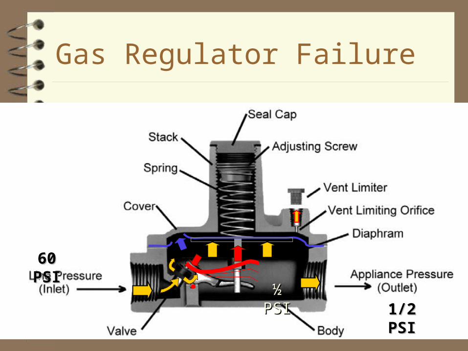
Gas Regulator Failure
1/2 PSI1/2 PSI½ PSI½ PSI
60 PSI60 PSI
2 PSI – 1/2 PSI Regulator
60 PSI - 2 PSI Regulator

Kitchen Hood
199,000 BTU/h at 6 in’s WC = ¼ PSI
2 PSI gas
Gas Shut-off Valve
50,000 BTU/h at 6 in’s WC = ¼ PSI

Local Gas Regulator w/ CSSTLocal Gas Regulator w/ CSST
IP OP
CAP.
1/4 PSI
5 PSICSST
(4) 50,000 BTU/H CSST

Vented Indoor Gas RegulatorVented Indoor Gas Regulator
Downstream shut-off valve
Gas regulator vent to outside provide weatherproof cap or gooseneck with insect screen
Truss Space
Plugged tee in dirt leg for upstream pressure measurement
Upstream Shut-off valve
Plugged tee for downstream pressure measurement
Gas Pressure Regulator located indoors
Roof

Rooftop PipingRooftop Piping

Typical Gas Appliance Piping ConnectionTypical Gas Appliance Piping Connection

Typical Gas AppliancesTypical Gas Appliances
Consult Manufacturer’s Literature for BTU’s/H Input
Donut Fryer

Typical Gas AppliancesTypical Gas Appliances
AGA Appliance Nameplate
Consult manufacturer’s literature for BTU’s/H input

Typical AGA Appliance NameplateTypical AGA Appliance Nameplate
Min. Clearances
Max. Press.
Min. Press.
Units (In. WC)
Fuel Type
Input BTUH
Manifold Press.
Venting Category
Source: NFPA 54 Handbook

Typical Water Heater InstallationTypical Water Heater Installation
Appliance Regulator/Controls
Flue to Category I Type “B” ventSource: NFPA 54 Handbook

Single vs Double wall FlueSingle vs Double wall Flue
Double wall provides a safer installation
Source: NFPA 54 Handbook
Single wall more susceptible to carbon monoxide leaks

Corroded Flue Pipe from High Efficiency Corroded Flue Pipe from High Efficiency Condensing Equipment.Condensing Equipment.

Typical Appliance Flue InstallationTypical Appliance Flue InstallationSource: NFPA 54 Handbook

Combustion AirCombustion Air
Transfer Grille
Ventilation louvers through ceiling & floors
Source: NFPA 54 Handbook

Combustion AirCombustion Air
Transfer grille / combustion air duct from attic to one foot above floor.
Ducted to outside walls.
Source: NFPA 54 Handbook

Commercial Commercial PropanePropane PropertiesProperties
Heat of combustion is measured in BTU’s/cu.ft. Propane = 2,500 2,500 BTU’s/CF (Caloric Value)
Specific Gravity of Propane = 1.521.52 (Air =1.00)– Propane is heavier than air. (It will pool in low places)
Flammability Limits (% Volume in air) – Lower = 2.4%, <<<<< Flame >>>>> Upper = 9.6%– Below 2.4% too lean for Combustion Above 9.6% too rich for
combustion
Combustion air requirements in Cubic Feet: – Per cu. foot of Propane = 25 cubic feet of air. – Per 100 BTU’s = 1 cubic foot of air.
1 Cubic Foot of Propane = 2,500 BTU’s

Commercial Commercial ButaneButane Properties Properties
Heat of combustion is measured in BTU’s/cu.ft. Butane = 3,200 3,200 BTU’s/CF (Caloric Value)
Specific Gravity of Butane = 1.951.95 (Air =1.00)– Butane is heavier than air. (It will pool in low places)
Flammability Limits (% Volume in air) – Lower = 1.9%, <<<<< Flame >>>>> Upper = 8.6%– Below 1.9% too lean for Combustion Above 8.6% too rich for
combustion
Combustion air requirements in Cubic Feet: – Per cu. foot of Propane = 32 cubic feet of air. – Per 100 BTU’s = 1 cubic foot of air.
1 Cubic Foot of Butane = 3,200 BTU’s

Multipliers for Gases other than .6 Specific GravityMultipliers for Gases other than .6 Specific Gravity
Propane
Butane
Nat. Gas
Convert CFH in Gas pipe sizing tables to CFH for a fuel with a specific gravity other than 0.6

Sizing Exercise #1Sizing Exercise #1

Approximate Gas input for Typical Gas AppliancesApproximate Gas input for Typical Gas Appliances
Source: NFPA 54 Handbook

Determining Gas Loads for sizingDetermining Gas Loads for sizing
Gas pipe sizing is accomplished by converting the gas input loads for HVAC, domestic water heating, cooking equipment and process equipment from BTUH to CFH of gas.
A delivery pressure and acceptable pressure drop are selected and the proper sizing chart or calculation can be used to size the pipe.

Determine heat load by calculating demand in BTU’s
Convert BTUH into CFH by dividing by 1000 for Natural Gas
Example: 2,500,000 BTUH divided by 1000 = 2,500 CFH
Converting from BTU’s/H to CFH of Converting from BTU’s/H to CFH of
Natural GasNatural Gas

HVAC Heating Load CalculationHVAC Heating Load Calculation
Engineer determines temperature to maintain Engineer calculates BTUH heat loss through
walls, floors and ceiling exposures. This is basis of BTU’s/Hour required to
maintain space heating. (Heating Load)

Domestic HW load Calc.Domestic HW load Calc.
Determine HW demand in GPH or GPM: For the following sizing examples we will assume 500
GPH demand of 140 degree HW Determine if Storage, Semi-instantaneous or
Instantaneous Water heaters will be used. Instantaneous Heaters require greater fuel loads.
500 Gallon
Review

Calculating HW DemandCalculating HW Demand
Multiply: (Gallons Per Hour) x (8.33 pounds per gallon) = (pounds of water/hr. at 1 deg. rise)– Example:Example: 500 GPH x 8.33 pounds per gallon = 4165 Pounds of 500 GPH x 8.33 pounds per gallon = 4165 Pounds of
HW per hour at 1 degree rise.HW per hour at 1 degree rise.
Multiply pounds of HW per hour by Temperature Rise (40
Degree to 140 degree rise = 100 degree rise) to get BTU’s/H.– Example:Example: 4165 Pounds of HW x 100 degree rise = 416,500 4165 Pounds of HW x 100 degree rise = 416,500
BTU’s/H BTU’s/H
Convert BTU’s to CFH– Example:Example: 416,500 BTU’s/H divided by 1000 BTU’s / Cubic Foot = 416,500 BTU’s/H divided by 1000 BTU’s / Cubic Foot =
416.5 CFH416.5 CFH
Review

Fuel Gas Pipe SizingFuel Gas Pipe Sizing
Determine the total developed length of pipe from the Gas Regulator to farthest the appliance connection.
Select a delivery pressure and determine allowable pressure drop. (0.3 - 0.5 in WC for low press. Up to 10% for medium pressure)
Total the CFH and select appropriate pipe sizes from the appropriate gas sizing tables.
For Branch sizing you can continue using the same developed length column for sizing or you can measure the actual developed length to the farthest fixture in each branch and use the appropriate developed length table for sizing only the branch piping.

Gas Pipe SizingGas Pipe SizingLongest Run MethodLongest Run Method
Determine length of piping from farthest appliance to gas pressure regulator and refer to sizing chart column that exceeds that length. (2,400 CFH total load @ 250 feet)
2,000,000 BTUH / 2,000 CFH burner
RegulatorWater
Heater
400,000 BTUH / 400 CFH burner
Meter
Furnace
Total developed length = 250 feet.
250 feet includes equivalent length allowance for fittings and valves.
See following page for equivalent length allowances table.

Nat. Gas Pipe sizing Table - 1/2 psi1/2 psiCFH of Gas at .6 specific gravity, Press. drop = 0.3 in WC
Length of tubing, FeetPipe
185 127 871-1/4”
100 250 500 100050
304
Diam.
442
277 191 1311-1/2” 455662
534 367 2522” 8771275
8990 6178 42466” 1475821472
90 62 431” 148215
1505 1034 7113” 24703594
3069 2109 14504” 50387330
Distance from RegulatorDistance from RegulatorTo farthest outletTo farthest outlet
Source: NFPA 54All sizing should be done from this column for 250’ systemAll sizing should be done from this column for 250’ system

Equivalent Lengths in Feet of Straight pipe. Equivalent Lengths in Feet of Straight pipe. For fittings and ValvesFor fittings and Valves
Source: NFPA 54 Handbook

1/2 PSI1/2 PSI Example:Example:

Gas Pipe Sizing - Gas Pipe Sizing - 1/2 PSI1/2 PSI
Determine length of piping from branch piping appliance to gas the pressure regulator and refer to sizing chart column that exceeds the branch length for sizing only the branch piping. (2,000 CFH branch load @ 100 feet)
2,000,000 BTUH = 2,000 CFH
RegulatorWater Heater
400,000 BTUH = 400 CFH
Meter
Furnace
Total developed length = 250 feet.
Length for Branch Sizing = 100’
4”4” @ 2,400 CFH (250’ Column)
2”@ 400 CFH
3” @ 2,000 CFH
(See sizing charts on following page for pipe sizing for 1/2 PSI gas.)

Nat. Gas Pipe sizing Table - 1/2 psi1/2 psiCFH of Gas at .6 specific gravity, Press. drop = 0.3 in WC
Length of tubing, FeetPipe
185 127 871-1/4”
100 250 500 100050
304
Diam.
442
277 191 1311-1/2” 455662
534 367 2522” 8771275
8990 6178 42466” 1475821472
90 62 431” 148215
1505 1034 7113” 24703594
3069 2109 14504” 50387330

5 PSI5 PSI Example:Example:

Gas Pipe Sizing - Gas Pipe Sizing - 5 PSI5 PSI
Determine length of piping from branch piping appliance to gas the pressure regulator and refer to sizing chart column that exceeds the branch length for sizing only the branch piping. (2,000 CFH branch load @ 100 feet)
2,000,000 BTUH = 2,000 CFH
RegulatorWater Heater
400,000 BTUH = 400 CFH
Meter
Furnace
Total developed length = 250 feet.
Length for Branch Sizing = 100’
1-1/2”1-1/2” @ 2,400 CFH (250’ Column)
1”@ 400 CFH
1-1/4” @ 2,000 CFH
(See sizing charts on previous pages for pipe sizing for 5 PSI gas.)

Nat. Gas Pipe sizing, Table - 5 psi5 psiCFH gas at .6 specific gravity, Press. drop = 10% or 1/2 psi
Length of tubing, FeetPipe
1710 1175 8081-1/4”
100 250 500 100050
2807
Diam.
4084
2562 1761 12101-1/2” 42046120
4934 3391 23312” 810111768
28358 19490 133964” 4655567736
833 572 3931” 13671989
7865 5405 37152-1/2” 1291118785
13903 9556 65683” 2282433209

Sizing Exercise #2Sizing Exercise #2
Place Sizing Chart on Overhead Projector
Use 1/2 PSI Table to Size Gas Piping to Gas Roof Top Units on a the roof of the “ASPE Industrial Building”

Nat. Gas Pipe sizing Table - 1/2 psi1/2 psiCFH of Gas at .6 specific gravity, Press. drop = 0.3 in WC
Length of tubing, FeetPipe
185 127 871-1/4”
100 250 500 100050
304
Diam.
442
277 191 1311-1/2” 455662
534 367 2522” 8771275
8990 6178 42466” 1475821472
90 62 431” 148215
1505 1034 7113” 24703594
3069 2109 14504” 50387330

Big Box Industrial Bldg. - Mech. Roof PlanBig Box Industrial Bldg. - Mech. Roof PlanNorth
Gas Pipe Sizing Exercise Gas Pipe Sizing Exercise #2#2
Size the Natural Gas Piping for 1/2 PSI1/2 PSI Gas at .03 PSI Press. Drop..03 PSI Press. Drop.
Roof Top AHU 200,000 BTUH (Typical) Regulator
100’
100’
100’
100’
100’
100’
100’
80’
200 CFH - 2”
Total feet of piping from PRV to last appliance = _____________
100’
Pipe Guard(Typical)
20’ down to Regulator
(PRV)
400
600
800
900’+90’(10% Fit’gs) =990’
1200
1400
1600
3
200
1800
3
4
4
4
4
6
66
2
1000
200 CFH - 2” 200 CFH 520’ - 2” 200 CFH 420’ - 2”
Use 1000’ Column on 1/2 PSI Chart
200 CFH 210’ 1-1/2”
200 CFH
1000’- 2”
No Scale
Meter
200 CFH 320’ - 2”
200 CFH 150’ - 1-1/2”
______ CFH / ___”
______ CFH / ___”
________ CFH / ___”
______ CFH / ___” ______ CFH / ___”
______ CFH / ___”
________ CFH / ___”
________ CFH / ___”
______ CFH / ___”

Nat. Gas Pipe sizing Table - 1/2 psi1/2 psiCFH of Gas at .6 specific gravity, Press. drop = 0.3 in WC
Length of tubing, FeetPipe
185 127 871-1/4”
100 250 500 100050
304
Diam.
442
277 191 1311-1/2” 455662
534 367 2522” 8771275
8990 6178 42466” 1475821472
90 62 431” 148215
1505 1034 7113” 24703594
3069 2109 14504” 50387330
1800 CFH

Sizing Exercise #3Sizing Exercise #3
Use 5 PSI Table to Size Gas Piping to the same Gas Roof Top Units on a the roof of the “ASPE Industrial Building”

Nat. Gas Pipe sizing, Table - 5 psi5 psiCFH gas at .6 specific gravity, Press. drop = 10% or 1/2 psi
Length of tubing, FeetPipe
1710 1175 8081-1/4”
100 250 500 100050
2807
Diam.
4084
2562 1761 12101-1/2” 42046120
4934 3391 23312” 810111768
28358 19490 133964” 4655567736
833 572 3931” 13671989
7865 5405 37152-1/2” 1291118785
13903 9556 65683” 2282433209

ASPE Industrial Bldg. - Mech. Roof PlanASPE Industrial Bldg. - Mech. Roof PlanNorth
Gas Pipe Sizing Exercise Gas Pipe Sizing Exercise #3#3
Size the Natural Gas Piping for 5 PSI5 PSI Gas at 10% (0.5 PSI) Press. Drop.10% (0.5 PSI) Press. Drop.
Roof Top AHU 200,000 BTUH (Typical) Regulator
100’
100’
100’
100’
100’
100’
100’
80’
200 CFH
710’ = 1”
Total feet of piping from PRV to last appliance = _____________
100’
Pipe Guard(Typical)
20’ down to Regulator
(PRV)
400
600
800
900’+90’(10% Fit’gs) =990’
1200
1400
1600
1-1/4”
200
1800
1-1/4”
1-1/4”
1-1/2”
1-1/2”
2”
2”
2”2”
1”
1000200 CFH -
620’ = 1” 200 CFH 520’ = 1” 200 CFH 420’ = 1”
Use 1000’ Column on 5 PSI Chart
200 CFH 210’ = 1”
200 CFH
810’= 1”
No Scale
Meter
200 CFH 320’ = 1”
200 CFH 150’ = 1”
______ CFH / ____
______ CFH / ____
________ CFH / ____
______ CFH / _____ ______ CFH / ____
______ CFH / ______
________ CFH / ____
________ CFH / ____
______ CFH / ____

Nat. Gas Pipe sizing, Table - 5 psi5 psiCFH gas at .6 specific gravity, Press. drop = 10% or 1/2 psi
Length of tubing, FeetPipe
1710 1175 8081-1/4”
100 250 500 100050
2807
Diam.
4084
2562 1761 12101-1/2” 42046120
4934 3391 23312” 810111768
28358 19490 133964” 4655567736
833 572 3931” 13671989
7865 5405 37152-1/2” 1291118785
13903 9556 65683” 2282433209
1800 CFH1/2 PSI gas required 6 inch pipe size1/2 PSI gas required 6 inch pipe size.

Gas Sizing TablesGas Sizing Tables

Increasing Gas Pressure
Increasing gas pressure can increase the pipe CFH capacity and reduce pipe sizes.
The following are some examples of ¾ inch pipe and 1 inch pipe at various pressures.
Note the one inch pipe capacity at ½ PSI = 100 CFH and at 50 PSI = 6,138 CFH.

Capacity of Semi-Rigid Tubing in CFH for Capacity of Semi-Rigid Tubing in CFH for 0.5 PSI0.5 PSI or less or less gas pressure and gas pressure and pressure drop of 0.3 Inches WCpressure drop of 0.3 Inches WC (0.60 Specific Gravity Gas)(0.60 Specific Gravity Gas)
0.5 PSI - 3/4” Pipe @ 200 feet = 0.5 PSI - 3/4” Pipe @ 200 feet = 30 CFH30 CFH
Source: NFPA 54 Handbook

Capacity of Semi-Rigid Tubing in CFH for Capacity of Semi-Rigid Tubing in CFH for 0.5 PSI0.5 PSI or less or less gas pressure and gas pressure and pressure drop of 0.5 Inches WCpressure drop of 0.5 Inches WC (0.60 Specific Gravity Gas)(0.60 Specific Gravity Gas)
0.5 PSI - 3/4” Pipe @ 200 feet = 0.5 PSI - 3/4” Pipe @ 200 feet = 39 CFH39 CFH
Source: NFPA 54 Handbook

Maximum Capacity of Pipe in CFH for Maximum Capacity of Pipe in CFH for 0.5 PSI0.5 PSI or less gas or less gas pressure and pressure and pressure drop of 0.3 Inches WCpressure drop of 0.3 Inches WC (0.60 Specific Gravity Gas)(0.60 Specific Gravity Gas)
1 PSI - 1” Pipe @ 200 feet = 1 PSI - 1” Pipe @ 200 feet = 100 CFH100 CFH
Source: NFPA 54 Handbook

Maximum Capacity of Pipe in CFH for Maximum Capacity of Pipe in CFH for 0.5 PSI0.5 PSI or less gas or less gas pressure and pressure and pressure drop of 0.5 Inches WCpressure drop of 0.5 Inches WC (0.60 Specific Gravity Gas)(0.60 Specific Gravity Gas)
0.5 PSI - 1” Pipe @ 200 feet = 0.5 PSI - 1” Pipe @ 200 feet = 135 CFH135 CFH
Source: NFPA 54 Handbook

Maximum Capacity of Pipe in CFH for Maximum Capacity of Pipe in CFH for 1 PSI1 PSI gas pressure gas pressure and a and a pressure drop of 10%pressure drop of 10% (0.60 Specific Gravity Gas)(0.60 Specific Gravity Gas)
1 PSI - 1” Pipe @ 200 feet = 1 PSI - 1” Pipe @ 200 feet = 338 CFH338 CFH
Source: NFPA 54 Handbook

Maximum Capacity of Pipe in CFH for Maximum Capacity of Pipe in CFH for 2 PSI2 PSI gas pressure gas pressure and a and a pressure drop of 10%pressure drop of 10% (0.60 Specific Gravity Gas)(0.60 Specific Gravity Gas)
2 PSI - 1” Pipe @ 200 feet = 2 PSI - 1” Pipe @ 200 feet = 525 CFH525 CFH
Source: NFPA 54 Handbook
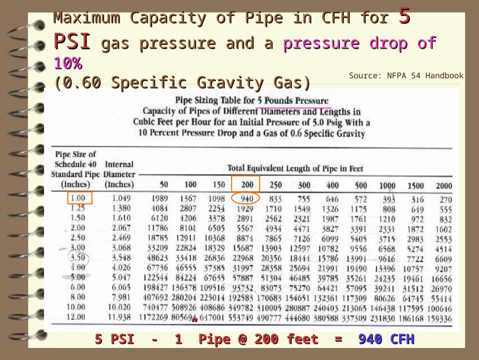
Maximum Capacity of Pipe in CFH for Maximum Capacity of Pipe in CFH for 5 PSI5 PSI gas pressure gas pressure and a and a pressure drop of 10%pressure drop of 10% (0.60 Specific Gravity Gas)(0.60 Specific Gravity Gas)
5 PSI - 1” Pipe @ 200 feet = 5 PSI - 1” Pipe @ 200 feet = 940 CFH940 CFH
Source: NFPA 54 Handbook

Maximum Capacity of Pipe in CFH for Maximum Capacity of Pipe in CFH for 10 PSI10 PSI gas pressure gas pressure and a and a pressure drop of 10%pressure drop of 10% (0.60 Specific Gravity Gas)(0.60 Specific Gravity Gas)
10 PSI - 1” Pipe @ 200 feet = 10 PSI - 1” Pipe @ 200 feet = 1,539 CFH1,539 CFH
Source: NFPA 54 Handbook

Maximum Capacity of Pipe in CFH for Maximum Capacity of Pipe in CFH for 20 PSI20 PSI gas pressure gas pressure and a and a pressure drop of 10%pressure drop of 10% (0.60 Specific Gravity Gas)(0.60 Specific Gravity Gas)
20 PSI - 1” Pipe @ 200 feet = 20 PSI - 1” Pipe @ 200 feet = 2,680 CFH2,680 CFH
Source: NFPA 54 Handbook

Maximum Capacity of Pipe in CFH for Maximum Capacity of Pipe in CFH for 50 PSI50 PSI gas pressure gas pressure and a and a pressure drop of 10%pressure drop of 10% (0.60 Specific Gravity Gas)(0.60 Specific Gravity Gas)
50 PSI - 1” Pipe @ 200 feet = 50 PSI - 1” Pipe @ 200 feet = 6,138 CFH6,138 CFH
Source: NFPA 54 Handbook

Questions?Questions?Fuel Gas Systems
by: Ron George, CPD
Ron George Design & Consulting Services
5818 Newport South Rd.
Newport, MI 48166
Ph: 734-322-0225
Cell: 734-755-1908