Embed Size (px)
Citation preview

Fuel Cell Modeling In AMESim
IMAGINE Specific Thermodynamic Applications 04/2006 Cédric ROMAN – [email protected]

ROMAN Cédric – [email protected]
2 Introduction
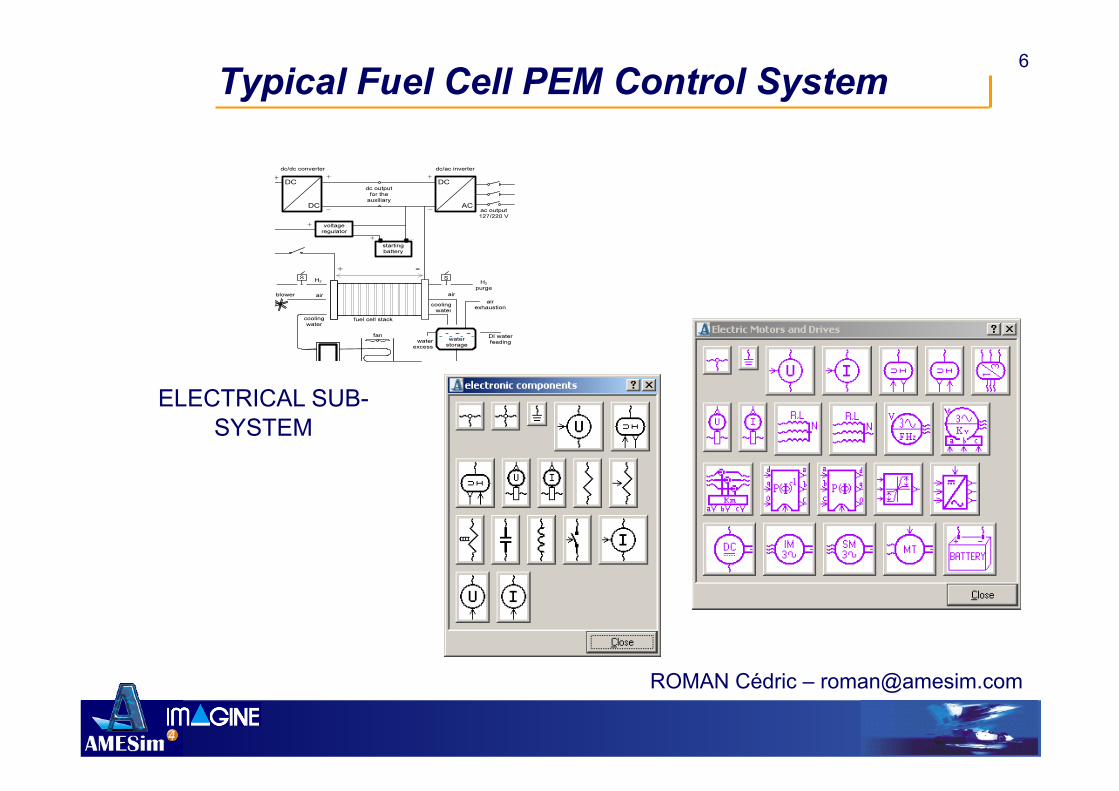
Fuel Cells are complex multi-domain dynamic systems Electrical, electrochemical, fluidic, thermal
phenomena are coupled Controlling such systems is a challenge to
ensure efficiency and reliability Modelling fuel cells systems implies
Interoperability Multi-disciplinary and dynamic simulation
environment
ROMAN Cédric – [email protected]
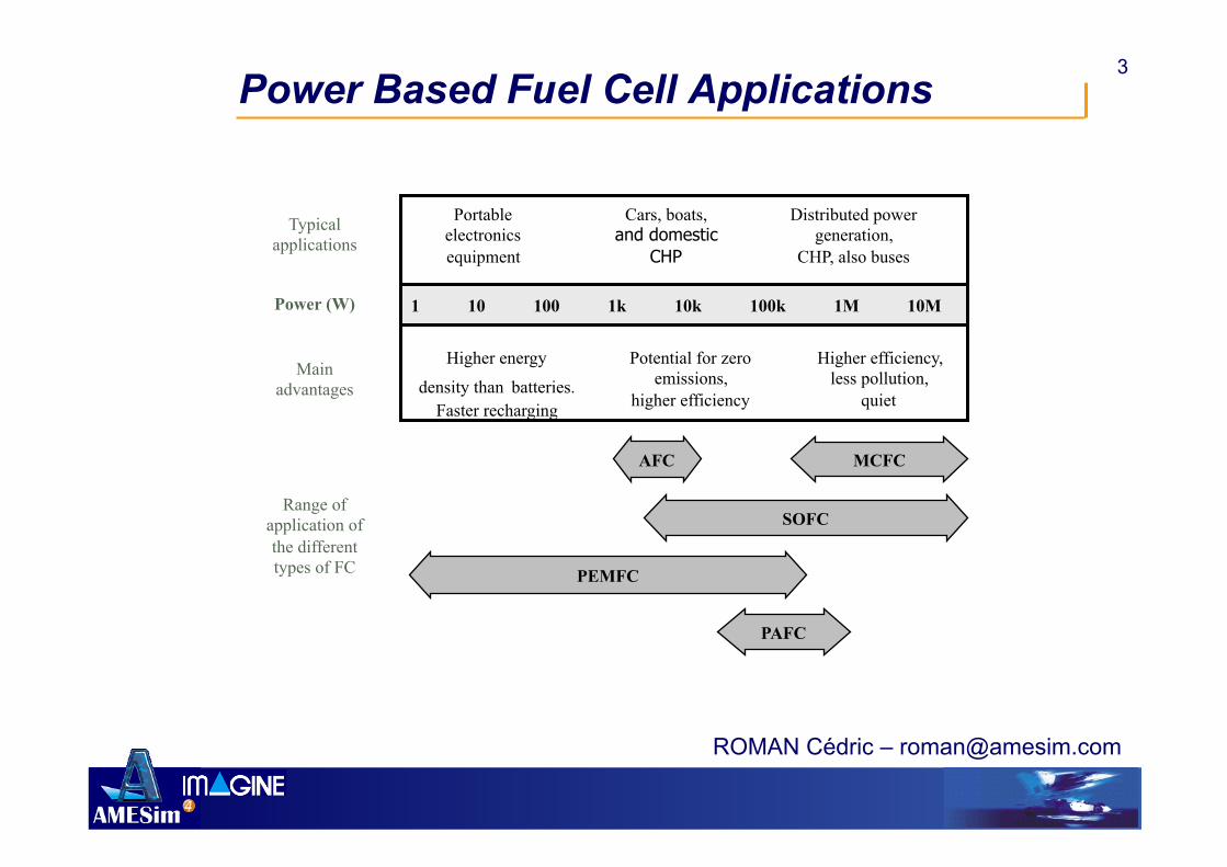
3 Power Based Fuel Cell Applications
1 10 100 1k 10k 100k 1M 10M
Portable electronics equipment
Cars, boats, and domestic
CHP
Distributed power generation,
CHP, also buses
Potential for zero emissions,
higher efficiency
Higher efficiency, less pollution,
quiet
AFC
PEMFC
SOFC
MCFC
Typical applications
Power (W)
Main advantages
Range of application of the different types of FC

ROMAN Cédric – [email protected]
12 Introduction
State of the art of PEMFC stack numerical models Dynamic model of analogic electrical equivalent
system Pneumatics and chemicals are modelled with equivalent
electric elements
Quasi-steady state model based on CFD code Limited by boundary conditions CPU cost: days on parallelized clusters
Bond-Graph model Multi-domain (electrical/chemical/pneumatic)

ROMAN Cédric – [email protected]
13 Stack System AMESim Model for stack modelling
Inspired from Bond Graph Physical model of electrical, electrochemical,
pneumatic and thermal phenomena Stack design and optimization Dynamic modelling of pneumatics, chemical
reactions, etc…

ROMAN Cédric – [email protected]
14
Diffusion Protonic resistance
PEM cell Model structure (Explanations)
membrane CL GDL
width
length/nel
heigth
x
y
H+ H+ H+ H+ H+
O2
O2 O2 O2
O2
Porous media
Catalyst
Conductive
flow rate
Protons from anodic reaction
gas mixture (O2,N2,H2O)
Cathode side

ROMAN Cédric – [email protected]
15
Current prediction
&
Ohmic losses
PEM cell Model structure (Explanations)
membrane CL GDL
e- e- e- e- e-
H2O H2O H2O H2O H2O
Electrochemical reaction
Nernst equation
Reaction kinetic
Diffusion

ROMAN Cédric – [email protected]
16 PEMFC Stack Model
Core of model electrochemical reaction
Interfaces Electrical circuit Electrolyte Catalyst layer
Electrical circuit
Catalyst layer
Electrolyte (membrane)
Reaction parameters Stoechiometry in data file
Reference heat of formation, standard entropy Kinetic parameters in data file
Partial orders, kinetic constant Assymetry parameter

ROMAN Cédric – [email protected]
17 PEMFC Stack model
PEMFC cathode Electrochemical reaction Gas mixture equilibrium
potential Nernst equation
Overpotential Activation Voltage
– Equilibrium potential = Disequilibrium
Reaction kinetic Butler-Volmer equation

ROMAN Cédric – [email protected]
18 PEMFC Stack model
Gas mixture description Dynamic description Mixture of N species Perfect gas equation of state
Real gas possible Thermodynamic description
JANAF 71: Cp, h, u, s given by 5 order polynomial of temperature Validity domain (200<->5000K)
Diffusion Binary coefficients / Wilke formula
Water condensation/vaporisation (to come…)
Predefined species

ROMAN Cédric – [email protected]
19 PEMFC Stack model
Add-on Gas Mixture
Basic Elements approach
Powerful features Initialisation facility
Compatibility with PCD/PN/THPN

ROMAN Cédric – [email protected]
20 PEMFC Stack model
Add-on Fuel Cells
Basic Elements approach
Compatible with Add-on Gas Mixture
Thermal libraries

ROMAN Cédric – [email protected]
21 PEMFC Stack model
Possible Discretizations
Catalyst layer Gas diffusion layer
Channel
7 nodes 13 nodes

ROMAN Cédric – [email protected]
22 PEMFC Stack model
Diffusion in
porous media
Thermal Exchange
Diffusion in
porous media
Electrochemical reaction
Ohmic losses
Double Capacitanc
e layer
Laminar flow in channel

ROMAN Cédric – [email protected]
24
AMESim Simulation Comparison of different architectures (different flowcharts) Design of the control of the PEMFC System Start-up process
freeze start Change of load
Drive cycle Power demand
PEMFC system simulation
Power demand

ROMAN Cédric – [email protected]
25 PEMFC AMESim model
Allow quick results Physical model Transient behaviour Gas diffusion efficiency Thermal management
Robustness & Risk analysis AMESim features
Monte-Carlo simulation Design of experiment Optimization
Sensitivity Analysis

ROMAN Cédric – [email protected]
26 PEMFC AMESim model
Gain Time & Performance
Have a better understanding of physics
Use all powerfuls AMESim applications Compatible with standard libraries Activity index Linear analysis (Bode, Nyquist, Nichols,…) Design of Experiment / Optimization Real-time