Embed Size (px)
Citation preview

Flash Technology, 332 Nichol Mill Lane, Franklin, TN 37067 (615) 261-2000
FTW 174-2 GPRS
Wireless Monitoring System Reference Manual
Part Number F7911742GPRS
SERIAL NUMBER

ii Revision 1 – 8-10-2012 FTW 174-2 GPRS
Front Matter
Abstract
This manual contains information and instructions for installing, operating and maintaining
the FTW 174-2 Wireless Monitoring System.
Copyright
Copyright © 2012, Flash Technology®, Franklin, TN, 37067, U.S.A.
All rights reserved. Reproduction or use of any portion of this manual is prohibited without
express written permission from Flash Technology and/or its licenser.
Trademark Acknowledgements
Flash Technology® is a registered trademark name.
ElectroFlash™, Flash Tech™, Flash Technology™, FTCA™, Flash™ and the Flash
Technology Logo are all trademarks of Flash Technology.
All trademarks and product names mentioned are properties of their respective companies
and are recognized and acknowledged as such by Flash Technology.
Disclaimer
While every effort has been made to ensure that the information in this manual is complete,
accurate and up-to-date, Flash Technology assumes no liability for damages resulting from
any errors or omissions in this manual, or from the use of the information contained herein.
Flash Technology reserves the right to revise this manual without obligation to notify any
person or organization of the revision.
In no event will Flash Technology be liable for direct, indirect, special, incidental, or
consequential damages arising out of the use of or the inability to use this manual.
Warranty
Flash Technology warrants all components, under normal operating conditions, for 1 year.

FTW 174-2 GPRS Revision 1 – 8-10-2012 iii
Table of Contents
Front Matter .............................................................................................................................. ii
Abstract ................................................................................................................................. ii
Copyright .............................................................................................................................. ii
Trademark Acknowledgements ............................................................................................ ii
Disclaimer ............................................................................................................................. ii
Warranty ............................................................................................................................... ii
List of Figures .......................................................................................................................... iv
List of Tables ........................................................................................................................... iv
Section 1 – Introduction ............................................................................................................ 1
Introduction ........................................................................................................................... 1
Description ............................................................................................................................ 1
Specifications ........................................................................................................................ 1
Section 2 – Initial On-Site Wireless Service Check ................................................................. 3
Unpacking ............................................................................................................................. 3
Important ............................................................................................................................... 3
Finding the Best Install Location .......................................................................................... 3
Section 3 – Mounting and Installation ...................................................................................... 4
Mounting ............................................................................................................................... 4
Installation............................................................................................................................. 4
AC Power Wiring ............................................................................................................. 4
Dry Contact Input Wiring ................................................................................................. 4
RS-485 Wiring .................................................................................................................. 4
Antenna Mounting Bracket ............................................................................................... 4
Grounding ......................................................................................................................... 4
Status Indicator LED’s .......................................................................................................... 6
Section 4 – Activation ............................................................................................................. 12
Monitoring .......................................................................................................................... 12
Section 5 – Recommended Spare & Replaceable Parts .......................................................... 13
Customer Service ................................................................................................................ 13
Ordering Parts ..................................................................................................................... 13
Disconnecting Power .......................................................................................................... 13
Return Material Authorization (RMA) Policy ........................................................................ 14

iv Revision 1 – 8-10-2012 FTW 174-2 GPRS
List of Figures
Figure 1-1 – FTW 174-2 Internal Wiring & Component Layout ............................................. 2
Figure 2-1 – Wireless Service Label ......................................................................................... 3
Figure 3-1 – AC Termination ................................................................................................... 5
Figure 3-2 – Dry Contact Input Label....................................................................................... 5
Figure 3-3 – PCB 9039 Layout and External Wiring ............................................................... 7
Figure 3-4 – Enclosure Mounting Footprint ............................................................................. 8
Figure 3-5 – RS-485 Installation with FTB Strobe System ...................................................... 9
Figure 3-6 – RS-485 Installation with FLC 36XX ................................................................. 10
Figure 3-7 – Antenna Universal Mounting Bracket ............................................................... 11
Figure 4-1 – Wireless Number ................................................................................................ 12
List of Tables
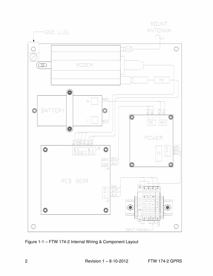
Table 3-1 – PCB 9039 LED’s ................................................................................................... 6
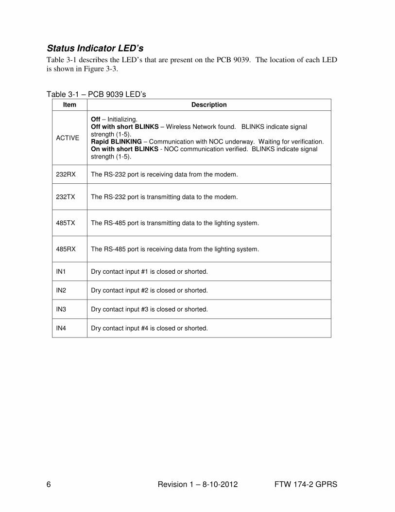
Table 5-1 – Major Replaceable Parts ...................................................................................... 13
Table 5-2 – Optional Items ..................................................................................................... 13

FTW 174-2 GPRS Revision 1 – 8-10-2012 1
Section 1 – Introduction
Introduction
The FTW 174-2 provides wireless
monitoring through RS-485
communications and/or four (4) dry
contact inputs. The unit also monitors site
power.
Equipment monitoring through RS-485
communications is available with all Flash
Technology FLC series controllers and
any FTB strobe system equipped with a
9038 or 4747 (Ver. 6.9 or higher) PCB.
Dry contacts are typically alarm relays
provided by equipment for external
monitoring of alarm conditions. Each
input of the FTW 174-2 can be configured
by Flash Technology’s National
Operations Center (NOC) to alarm on
either open or closed status. Alarm on
open is preferred for fail safe
monitoring.
All alarm and communication monitoring
is handled by the NOC.
PLEASE NOTE
Before permanently installing and/or
wiring the wireless monitoring unit,
power-up the system on-site to ensure
wireless service in your area. Refer to
Section 2 for detailed instructions.
Description
The component layout and internal wiring
of the unit is shown in Figure 1-1. The dry
contact inputs are located on J2 of PCB
9039 as shown in Figure 3-3.
Specifications
Physical
13.33H x 11.30W x 5.60D inches
(External)
10 lbs.
Electrical
AC Voltage 120 VAC, 60 Hz
Power 7VA
Battery Operation 24+ hrs
2 Revision 1 – 8-10-2012 FTW 174-2 GPRS
Figure 1-1 – FTW 174-2 Internal Wiring & Component Layout

FTW 174-2 GPRS Revision 1 – 8-10-2012 3
Section 2 – Initial On-Site Wireless Service Check
Unpacking
Inspect shipping cartons for signs of
damage before opening them. Check
package contents against the packing list
and inspect each item for visible damage.
Report damage claims promptly to the
freight handler.
Important
The following steps will verify wireless
service in your area and must be
performed at the location where the unit is
to be installed. A label located on the
inside front cover of the monitoring unit is
provided to call attention to this process.
Figure 2-1 depicts the label noted above.
Prior to installation, the on-site technician
should apply 120 VAC to the unit and then
monitor the green LED indicator labeled
“ACTIVE” on PCB 9039 for status. See
Figure 3-3 for location of the LED. If
wireless service is available, the LED will
indicate signal strength by a series of short
blinks (1-5). Once a wireless signal is
found, the unit will attempt to connect to
the NOC. This operation is indicated by
rapid blinking of the LED. If
communication is achieved, the
“ACTIVE” LED will be solid on with
short blinks to indicate signal strength (1-
5). This process may take several minutes.
See Figure 2-1 for complete details of the
“Active” LED.
Finding the Best Install Location
Move the external antenna to different
locations to find the maximum signal
strength available at the site, as indicated
by the number of ACTIVE LED blinks.
This will help determine the location
where the FTW 174-2 should be mounted.
Upon successful completion of these steps,
shut off power to the unit and proceed
with installation.
Prior to installation, apply power to the unit and observe the "ACTIVE" LED to verify service.
Please note that this sequence may take several minutes to complete.
OFF - Initializing.
OFF with short BLINKS - Wireless network found. Number of short blinks
indicates signal strength (1 - 5).
RAPID BLINKING - Communication with NOC underway. Waiting for verification.
ON with short BLINKS - Communication with NOC verified. Number of short blinks
indicates signal strength (1 - 5). Begin installation.
Contact the NOC at (800) 821-5825 for technical support.
ATTENTION
P/N 3905210Rev A
Figure 2-1 – Wireless Service Label

4 Revision 1 – 8-10-2012 FTW 174-2 GPRS
Section 3 – Mounting and Installation
Mounting
The base of the unit has four (4) mounting
feet as shown in Figure 3-4. Mounting
hardware is not included.
Installation
AC Power Wiring
AC Power terminal block TB1
incorporates MOV1 and Fuse F1 for
increased protection against AC Power
transients. Also, fuseholder TB1 acts as a
power disconnect to the unit. Grasp the
fuseholder on the sides and pull forward to
disconnect power.
Connect 120 VAC power to terminal
block TB1 (L, N, GND) as shown in
Figure 3-1, but leave power turned off
until you are ready for activation (see
Section 4). The terminal block uses
spring-cage contacts to provide rugged,
trouble-free connections which are
vibration-proof and gas-tight, thus
providing long-term stability. The
conductor contact force is determined by
the spring tension and so is independent of
the user tightening torque as with screw
type terminals.
To install a wire, follow these steps:
1. Strip the insulation, exposing 0.4 inch
(10 mm) or more of conductor.
2. Insert a standard 1/8” width
screwdriver (supplied) into the
rectangular slot and push. This causes
the spring clip to open.
3. Insert the conductor fully into the
round terminal compartment and then
remove the screwdriver. The
conductor automatically makes
contact.
4. Check that contact is made to
conductor metal and not insulation.
Dry Contact Input Wiring
Connect the equipment to be monitored
via dry contact inputs as shown in Figure
3-3. A label has been provided on the
inside cover of the unit to record each
input, up to four (4), that is connected.
Figure 3-2 depicts the dry contact input
label.
RS-485 Wiring
Connect the equipment to be monitored
via RS-485 as shown in Figures 3-5 or 3-6.
Figure 3-3 shows the layout of the PCB
9039 board.
Antenna Mounting Bracket
The supplied Antenna Universal Mounting
Bracket Kit (PN 1905353) provides
multiple mounting options for the
magnetic mount antenna, permitting
installation in the optimum location for
best signal strength and reliable
communication. The bracket permits
mounting on wall, Uni-strut, or pole
(Figure 3-7) and the bracket material is
galvanized for long life and ferrous for
firm attraction of the antenna’s magnetic
base. The bracket also permits mounting
of a photocell in either of two holes on the
top plate.
Grounding
To provide increased immunity from
lightning damage to the FTW 174-2, it is
essential that the Ground Lug located in
the upper left corner of the FTW baseplate
(Figure 1-1) be properly connected by a
No. 2 AWG conductor to the site
Grounding System. Observe proper
Grounding Procedures.

FTW 174-2 GPRS Revision 1 – 8-10-2012 5
Figure 3-1 – AC Termination
Figure 3-2 – Dry Contact Input Label
6 Revision 1 – 8-10-2012 FTW 174-2 GPRS
Status Indicator LED’s
Table 3-1 describes the LED’s that are present on the PCB 9039. The location of each LED
is shown in Figure 3-3.
Table 3-1 – PCB 9039 LED’s
Item Description
ACTIVE
Off – Initializing. Off with short BLINKS – Wireless Network found. BLINKS indicate signal strength (1-5). Rapid BLINKING – Communication with NOC underway. Waiting for verification. On with short BLINKS - NOC communication verified. BLINKS indicate signal strength (1-5).
232RX The RS-232 port is receiving data from the modem.
232TX The RS-232 port is transmitting data to the modem.
485TX The RS-485 port is transmitting data to the lighting system.
485RX The RS-485 port is receiving data from the lighting system.
IN1 Dry contact input #1 is closed or shorted.
IN2 Dry contact input #2 is closed or shorted.
IN3 Dry contact input #3 is closed or shorted.
IN4 Dry contact input #4 is closed or shorted.

FTW 174-2 GPRS Revision 1 – 8-10-2012 7
Figure 3-3 – PCB 9039 Layout and External Wiring

8 Revision 1 – 8-10-2012 FTW 174-2 GPRS
Figure 3-4 – Enclosure Mounting Footprint

FTW 174-2 GPRS Revision 1 – 8-10-2012 9
Figure 3-5 – RS-485 Installation with FTB Strobe System

10 Revision 1 – 8-10-2012 FTW 174-2 GPRS
Figure 3-6 – RS-485 Installation with FLC 36XX

FTW 174-2 GPRS Revision 1 – 8-10-2012 11
Figure 3-7 – Antenna Universal Mounting Bracket
Wall Mount
Use screws to mount to the inside or outside wall of a
shelter.
(Screws are not included in the kit.)
Horizontal Uni-strut Mount
Use spring-nuts to mount to Uni-strut.
(Spring-nuts are not included in the kit.)
Vertical Pole or H-frame post Mount
Use 3” U-bolt (included) to mount to pole or H-frame post.
The bracket permits use of larger U-bolts, up to 5”.

12 Revision 1 – 8-10-2012 FTW 174-2 GPRS
Section 4 – Activation
Monitoring
Once the installation is complete, follow
the procedure below to activate the service
and begin monitoring:
1. Please be prepared to provide the
following information:
The wireless number for this unit. See
Figure 4-1. The card is located on the
inside front cover.
Your name, contact number and
company.
If monitoring an FCC registered tower
site, the site number and FCC number.
Descriptions of the items being
monitored by each input.
2. Re-apply power to the equipment and
observe the “Active” LED shown in
Figure 3-3. Once the LED is “On with
short BLINKS”, communication with
the NOC has been established. This
process may take several minutes.
Refer to Figure 2-1 and Table 3-2 for
complete details of the “Active” LED.
3. Secure the external antenna on the
Antenna Mounting Bracket in a
location which provides maximum
signal strength as indicated by the
number of ACTIVE LED blinks
4. Connect the red wire to + (Positive)
and the black wire to – (Negative) on
the battery as shown in Figure 1-1.
5. Call 1-800-821-5825 to initiate
monitoring while on-site. The NOC
technician will request several tests to
be performed to verify correct
installation and operation of the
system.
6. Please note that once the unit is
powered and communication is
established, it will automatically send
a message to the NOC to initiate
service and billing will begin.
Figure 4-1 – Wireless Number
FTW 174-2 GPRS Revision 1 – 8-10-2012 13
Section 5 – Recommended Spare & Replaceable Parts
Customer Service
Customer Service: (800) 821-5825
Telephone: (615) 261-2000
Facsimile: (615) 261-2600
Shipping Address:
Flash Technology
332 Nichol Mill Lane
Franklin, TN 37067
Ordering Parts
To order spare or replacement parts, contact customer service at 1-800-821-5825.
Table 5-1 – Major Replaceable Parts
Reference Description Part Number
MODEM Wireless Modem (GPRS) 5905200
HARNESS Harness, FTW 174, Modem Signal 4905205
BATTERY 12V Battery 4991875
POWER Power Supply 5905202
POWER Fuse 2 Amp Slow Blow 5x20 mm 11000008012
PCB 9039 Board, Modem Interface 2903911
ANTENNA External w/ 12’ (ft) cable 4905227
ANTENNA Kit Antenna Mounting Bracket 1905353
TB1 FUSE 3 AMP 3AB 4150218
TB1 Varistor 130V 6901079
Table 5-2 – Optional Items
Reference Description Part Number
CABLE RS-485; Single Pair, 22 AWG, Red/Black 5905302
CABLE Dry Contacts; 4 Pair, 22 AWG, Red/Black 5993101
Disconnecting Power
When removing power from the equipment, ensure that the red wire to the battery is
disconnected first. Reconnect battery after work is completed.

14 Revision 1 – 8-10-2012 FTW 174-2 GPRS
Return Material Authorization (RMA) Policy IF A PRODUCT PURCHASED FROM FLASH TECHNOLOGY MUST BE RETURNED FOR ANY REASON (SUBJECT TO THE WARRANTY POLICY), PLEASE FOLLOW THE PROCEDURE BELOW:
Note: An RMA number must be requested from Flash Technology prior to shipment of any product. No returned product will be processed without an RMA number. This number will be the only reference necessary for returning and getting information on the product’s progress.
Failure to follow the below procedure may result in additional charges and delays. Avoid unnecessary screening and evaluation charges by contacting Technical Support prior to returning material.
1. To initiate an RMA, customers should call Flash Technology’s Network Operation Center at (800-821-5825) to receive technical assistance and a Service Notification number. The following information is required before a Service Notification number can be generated:
• Site Name/Number / FCC Registration number/ Call Letters or Airport Designator
• Site Owner (provide all that apply – owner, agent or subcontractor) o Contractor Name o Contractor Company
• Point of Contact Information: Name, Phone Number, Email Address, Fax Number and Cell Phone (or alternate phone number)
• Product’s Serial Number
• Product’s Model Number or part number
• Service Notification Number (if previously given)
• Reason for call, with a full description of the reported issue
2. The Service Notification number will then serve as a precursor to receiving an RMA number if it is determined that the product or equipment should be returned. To expedite the RMA process please provide:
• Return shipping method
• Purchase Order (if non-warranty repair)
• Shipping Address
• Bill To Address
• Any additional information to assist in resolving the issue or problem
3. A P.O. is required in advance for the replacement of product that may be under warranty. Flash will then, at its discretion issue a credit once the validity of the warranty has been determined.
4. A purchase order (P.O.) is also required in advance for all non-warranty repairs. NOTE: the purchase order is required prior to the issuance of the RMA number.
• If the P.O. number is available at the time of the call, an RMA number will be issued and the customer must then fax or email the P.O. with the RMA number as the reference, to ensure prompt processing.
• If the P.O. number is NOT available at the time of the call, a Service Notification Number will be given to the customer and should be referenced on the P.O. when faxed or emailed to RMA Rep.
• Flash will then, at its discretion repair or replace the defective product and return the product to the customer based on the shipping method selected.
• The customer may purchase a new product before sending in the existing product for repair. If Flash Technology determines the existing product is still covered under warranty a credit will be issued to the customer for the new product.
5. After receiving the Flash Technology RMA number, please adhere to the following packaging guidelines:
• All returned products should be packaged in a way to prevent damage in transit. Adequate packing should be provided taking into account the method of shipment.
Note: Flash Technology will not be responsible for damaged items if product is not returned in appropriate packaging.
6. All packages should clearly display the RMA number on the outside of all RMA shipping containers. RMA products (exact items and quantity) should be returned to:
Flash Technology Attn: RMA #XXX 332 Nichol Mill Lane Franklin, TN 37067
7. All RMA numbers:
• Are valid for 30 days. Products received after may result in extra screening and delays.
• Must have all required information provided before an RMA number is assigned.
Return to Stock Policy • Parts can be returned within 60 days of ship date and will be subject to a 25% restocking fee. Product
must: o Be in the original packaging o Not be damaged
• After 60 days no parts can be returned