Embed Size (px)
Citation preview
APPLICATION OF THE VORTEX-LATTICE TECHNIQUE TO THE ANALYSIS OF THIN WINGS WITH VORTEX SEPARATION AND THICK MULTI-ELEMENT WINGS
Charles FT. Smith and Ishwar C. Bhateley Fort Worth Division of General Dynamics
SUMMARY
Two techniques f o r extending the range of app l i cab i l i ty of the basic vor tex- la t t ice method a r e discussed. The f i r s t tech- nique improves the computation of aerodynamic forces on th in , low-aspect-ratio wings of a r b i t r a r y planforms a t subsonic Mach numbers by including the e f f e c t s of leading-edge and t i p vortex separation, cha rac te r i s t i c of t h i s type wing, through use of the well-known suction-analogy method of E. C. Polhamus. Comparisons with experimental data fo r a var ie ty of planforms a r e presented.
The second technique cons is t s of the use of the vortex- l a t t i c e method t o predic t pressure d i s t r ibu t ions over thick multi- element wings (wings with leading- and t rai l ing-edge devices). A method of laying out the l a t t i c e i s described which gives accurate pressures on the top and pa r t of the bottom surface of the wing. Limited comparisons between the r e s u l t predicted by t h i s method, the conventional l a t t i c e arrangement method, experi- mental data , and 2-D po ten t i a l flow analysis techniques a re presented.
INTRODUCTION
Vortex-lat t ice methods are known to give reasonable r e s u l t s f o r th in wings of moderate to high aspect r a t i o . However, use of these methods to predic t the aerodynamic forces on low-aspect- r a t i o wings has not been p r a c t i c a l due to the s ign i f i can t vortex l i f t generated by these wings. The analysis and predict ion of the nonl inear i t ies associated with the vortex l i f t has received con- s iderable a t t en t ion i n the l i t e r a t u r e f o r many years. Methods of solut ion based on complex mathematical models have generally f a i l e d . However, within the past several years, E. C. Polhamus of the NASA Langley Research Center has proposed and ve r i f i ed through comparison with experimental data an ana ly t i ca l method f o r sharp-leading-edge wings of zero taper r a t i o (reference 1 ) . The
https://ntrs.nasa.gov/search.jsp?R=19760021089 2018-05-23T23:00:10+00:00Z
method is based on a leading-edge suction analogy proposed by Polhamus in reference 2. Extension of the suction analogy to ; /
I
plane rectangular rings has been accomplished by J. E. Lamar in reference 3. A method for calculating the lift, drag, and pitching moment of cambered, sharp-edged wings of arbitrary plan- . ... form is presented here as a logical extension of the suction- i analogy concept. A vortex-lattice program is utilized to provide the potential-flow force coefficients required by the suction- analogy concept and to provide the foundation for development of a computer procedure which incorporates the methods developed.
The accurate calculation of pressure dis tributions near the leading edge of thick multi-element wings is of considerable interest to the aerodynamicist. Vortex-lattice methods using the conventional vortex-lattice arrangement of distributing the vor- ticity on the camber surface yield pressure coefficients which approach infinity at the leading edge due to the singularity at the leading edge. An alternate method of laying out the lattice is described which circumvents this difficulty and gives reason- able predictions for the pressures on the top surface and a part of the bottom surface of wings.
SYMBOLS
Values are given in both SI and U.S. Customary Units. The measurements and calculations were made in U.S. Customary Units.
AR aspect ratio
mean aerodynamic chord, cm (in. )
axial- force coefficient
drag-due-to-lift coefficient
total lift coefficient ( C L ~ + CL~)
zero-suction potential-flow lift coefficient
vortex-lift coefficient
total pitching-moment coefficient
zero-suction potential-flow pitching-moment coefficient for half-span wing
CN normal-force coefficient
potential-flow normal-force coefficient for half- span wing
pressure coefficient
potential-flow leading-edge suction coefficient for half-span wing
potential-flow leading-edge thrust coefficient for half-span wing
20 tential-flow side-force coefficient for half- span wing
potential-flow side-force-coefficient contribution from streamwise members of the vortex lattice for half-span wing
Ccc nozzle momentum coefficient
KP potential-f low normal-force slope
(Kp)m potential-flow constant used in pitching-moment calculation
Kv vortex- lif t constant
K~~~ leading-edge vortex-lift constant used in lift calculation
(Kv~~)m leading-edge vortex-lift constant used in pitching- moment calculations
K v ~ ~ ~ tip vortex- lif t constant used in lift calculations
( K v ~ ~ ~ ) m tip vortex- lif t constant used in pi tching-moment calculations
M Mach number
pitching-moment arm for tip vortex-lift contribu- tions, cm (in.)
pitching-moment arm for leading-edge vortex-lift contributions, cm (in.)
nondimensionalized chordwise locat ion 8 pitching-moment arm f o r leading-edge suct ion force, cm ( i n . )
' L
angle of a t tack , degrees i
planform taper r a t i o
leading-edge sweep angle, degrees
slope of the mean l i n e perpendicular t o the planform leading edge, degrees
THEORETICAL DEVELOPMENT FOR THIN WINGS
The Po lhamus Suc t ion h a logy
The General Dynamics vor tex - l a t t i ce method has been modi- f i e d t o incorporate the calculat ion of vortex separat ion e f fec t s . , '
The basis f o r t h i s modification t o the vor tex - l a t t i ce pro- cedure is the Polhamus leading-edge suct ion analogy, which is de ta i led i n reference 2. Brief ly , i t i s based on the postulate t h a t the normal force on the upper surface i s the same f o r attached vortex flow as the leading-edge suction force f o r attached potent ia l flow. The t o t a l l i f t of sharp-edged, pointed- t i p wings is given as :
CL = c ~ p + Cs cos a
is the potential-flow l i f t and CS i s the leading-edge suct ion orce. Polhamus wri tes the l i f t i n terms of K-factors, where K and Kv, which a re functions of planform and Mach number only. At is,
2 2 CL = Kp s i n a cos a + Kvv s i n a cos a LE
where Kp i s , by de f in i t ion , the normal-force slope given by potent ia l - f low theory,
rr a C N ~
"P a s i n a cos a
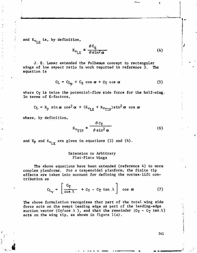
I i and Kv i s , by def in i t ion , LE
J. E . Lamar extended the Polhamus concept to rectangular wings of low aspect r a t i o i n work reported i n reference 3. The equation i s
CL ' c ~ p 4- cs COS a + Cy C J S Or
where Cy i s twice the potential-flow s i d e force f o r the half-wing. In terms of K-factors,
2 CL = Kp s i n a cos a + (KVLE + KvTIp ) s i n 2 a cos a
where, by de f in i t ion ,
CY
and Kp and Kv a re given i n equations (3) and (4) . LE
Ex tension to Arbitrary Fla t -Pla te Wings
The above equations have been extended (reference 4) to more complex planforms. For a trapezoidal planform, the f i n i t e t i p e f f e c t s a re taken i n t o account f o r defining the v o r t e x - l i f t con- t r ibu t ion as
CT + Cy - CT tan '4 cos a cos ,4 I The above formulation recognizes tha t pa r t of the t o t a l wing s ide force a c t s on the swept leading edge as pa r t of the leading-edge i suct ion vector (CT/COS A ) , and t h a t the remainder (Cy - CT tan A ) a c t s on the wing t i p , as shown i n f igure l ( a ) .
[ &
i
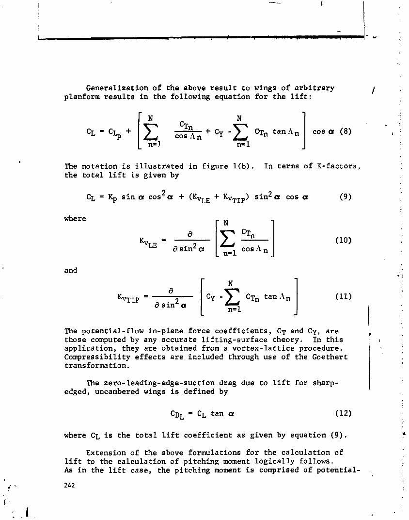
Generalization of the above r e s u l t to wings of a r b i t r a r y planform r e s u l t s i n the following equation f o r the l i f t :
I N . . - %
CTn + Cy -c C tan A cos a (8) cos A ' ;.
n=1
The notation i s i l l u s t r a t e d i n f igure l ( b ) . In terms of K-factors, >
the t o t a l l i f t is given by
where
2 CL = Kp s i n a cos a + (KvLE + KvTIp) s i n 2 a cos a (9)
and
The potential-flow in-plane force coeff ic ients , CT and Cy, a re those computed by any accurate l i f t ing-surface theory. In t h i s appl icat ion, they are obtained from a vor tex - l a t t i ce procedure. Compressibility e f f e c t s a r e included through use of the Goethert transformation.
The zero-leading-edge-suction drag due to l i f t fo r sharp- edged, uncambered wings is defined by
where CL i s the t o t a l l i f t coef f ic ient a s given by equation (9) .
Extension of the above formulations fo r the calculat ion of l i f t to the calculat ion of pitching moment logica l ly foll.ows. As i n the l i f t case, the pitching moment i s comprised of potent ial-
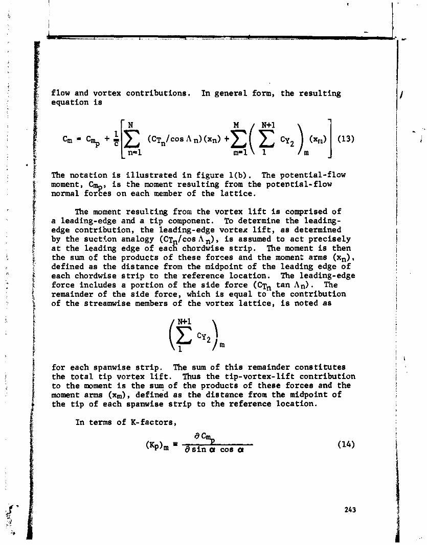
flow and vortex contributions. In general form, the r e su l t ing equation is
The notat ion i s i l l u s t r a t e d i n f igure l ( b ) . The potential-flow moment, Cmpy i s the moment r e su l t ing from the potential-flow normal forces on each member of the l a t t i c e .
The moment r e su l t ing from the vortex l i f t is comprised of a leading-edge and a t i p component. To determine the leading- edge contribution, the leading-edge vortex l i f t , a s determined by the suct ton analogy (C~,/cos An), i s assumed to a c t precisely a t the leading edge of each chordwise s t r i p , The moment is then the sum of the products of these forces and the moment arms (xn), defined as the dis tance from the midpoint of the leading edge of each chordwise s t r i p t o the reference locat ion. The leading-edge force includes a portion of the s ide force (CT* tan An). The remainder of the s ide force, which is equal t o the contribution of the streamwise members of the vortex l a t t i c e , i s noted as
fo r each spanwise s t r i p . The sum of t h i s remainder cons t i tu tes the t o t a l t i p vortex l i f t . Thus the tip-vortex- l i f t contribution to the moment i s the sum of the products of these forces and the moment arms ( x ~ ) , defined as the dis tance from the midpoint of the t i p of each spanwise s t r i p to the reference locat ion.
I n terms of K-factors,
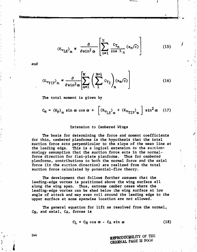
d c ' ~ n (xn/C)
( K v ~ ~ ) m ds in2 a 15 cos A J
The t o t a l moment i s given by
] s i n 2 a (17) Cm - (Kp), s i n a cos a +
Extension to Cambered Wings
The bas is f o r determining the force and moment coe f f i c i en t s f o r thin, cambered planforms i s the hypothesis t h a t the t o t a l suction force a c t s perpendicular to the slope of the mean l i n e a t the leading edge. This i s a logica l extension to the suztion- analogy assumption t h a t the suct ion force a c t s i n the normal-
#
force d i rec t ion f o r f la t -p la t e planforms . Thus f o r cambered planforms, contributions t o both the normal force and the a x i a l force ( i n the s x t i o n d i rec t ion) a re rea l ized from the t o t a l i
suction force calculated by potential-flow theory.
The development tha t follows fu r the r assumes t h a t the leading-edge vortex is positioned above the wing surface a l l along the wing span. Thus, extreme camber cases where the leading-edge vortex can be shed below the wing surface a t low angle of a t t ack and may even r o l l around the leading edge t o the upper surface a t some spanwise locat ion a re not allowed.
The general equation fox l i f t a s resolved from the normal, CN, and a x i a l , CA, forces is
CL = CN cos a - CA s i n a (18)
REpRoDUCIcBILW OF THE ORIOZNfi PAGE E POOR
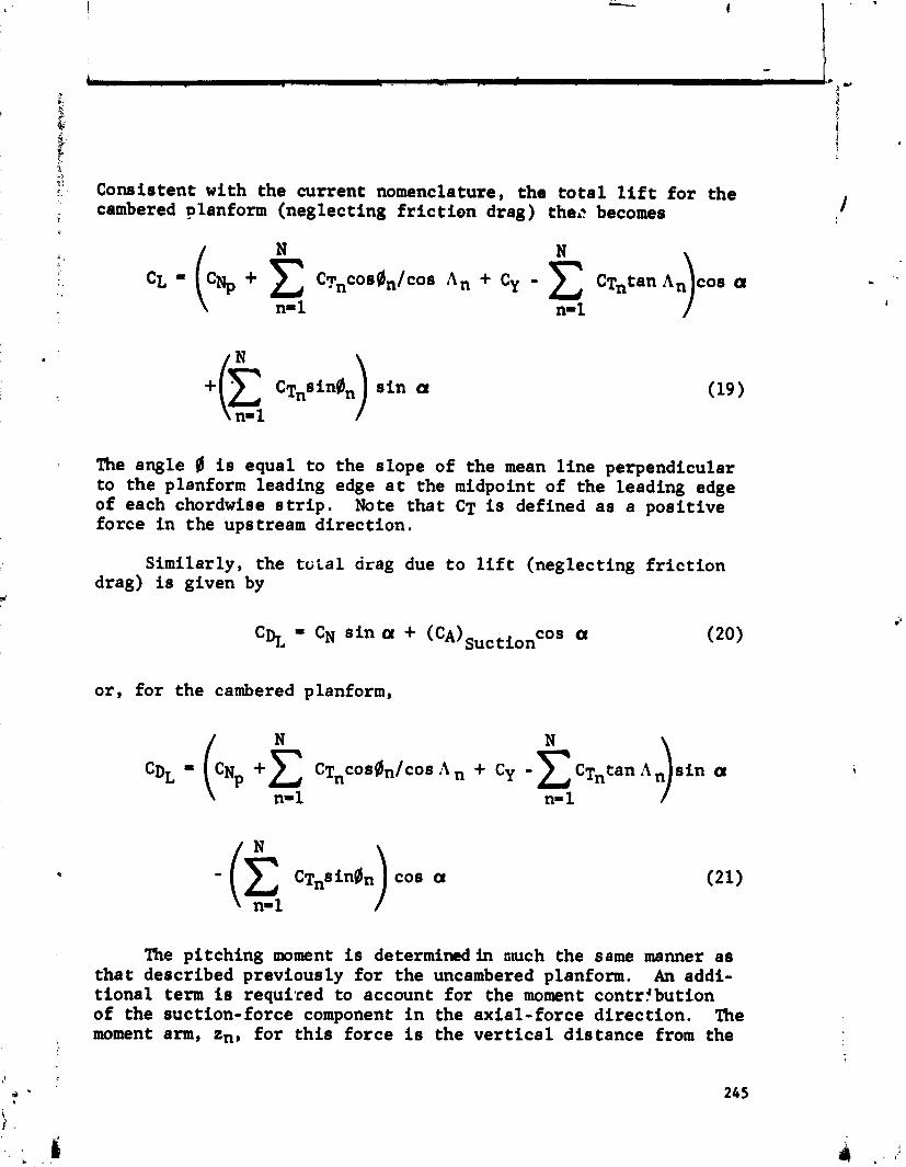
Consistent with the current nomenclature, the t o t a l l i f t f o r the cambered ~ l a n f o r m (neglecting f r i c t i o n drag) the.? becomes
+ C cTnsingn s i n a c1 1 The angle 0 is equal to the slope of the mean l i n e perpendicular to the planform leading edge a t the midpoint of the leading edge of each chordwise s t r i p . Note tha t CT is defined a s a posi t ive force i n the upstream di rec t ion ,
Similarly, the t o t a l drag due t o l i f t (neglecting f r i c t i o n drag) is given by
or , fo r the cambered planform,
The pitching moment i s determinedin ntuch the same manner a s tha t described previously f o r the uncambered planform. An addi- t iona l term is required to account f o r the moment contrfbution of the suction-force component i n the axial-force d i rec t ion . h e moment arm, zn, fo r t h i s force i s the v e r t i c a l dis tance from the
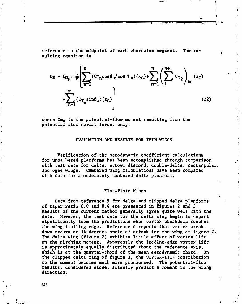
reference t o the midpoint of each chordwise segment. The re- su l t ing equation is
is the potential-flow moment resul t ing from the potentia -flow normal forces only. where
EVALUATION AND RESULTS FOR THIN WINGS
Verif icat ion of the aerodynamic coeff ic ient calculat ions f o r unca,: 5ered planforms has been accomplished through comparison $ with t e s t data fo r de l t a , arrow, diamond, double-delta, rectangular , and ogee wings. Cambered wing calculat ions have been compared with data f o r a moderately cambered de l t a planform.
Fla t-Pla t e Wings f
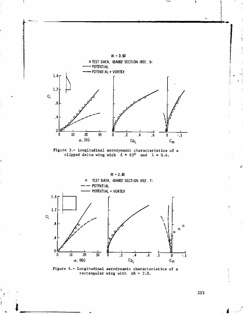
Data from reference 5 f o r d e l t a and clipped de l t a planforms t
of taper r a t i o 0.0 and 0 . 4 a re presented i n f igures 2 and 3. Results of the current method generally agree qui te well with the data. However, the t e s t data f o r the de l t a wing begin to depart t
s ign i f i can t ly from the predict ions when vortex breakdown reaches the wing t r a i l i n g edge. Reference 6 reports tha t vortex break- down occurs a t 14 degrees angle of a t t ack f o r the wing of f igure 2 . The de l t a wing ( f igure 2 ) exhib i t s l i t t l e e f f e c t of vortex l i f t on the pitching moment. Apparently the leading-edge vortex l i f t is approximately equally d i s t r ibu ted about the reference ax i s , which is a t the quarter-chord of the mean aerodynamic chord. On the clipped de l t a wing of f igure 3, the v o r t e x - l i f t contr ibut ion to the moment becomes much more pronounced. The potential-flow r e s u l t s , considered alone, ac tua l ly predict a moment i n the wrong direc t ion .
Comparisons between the theore t ica l r e s u l t s and data from reference 7 f o r an aspect-ratio-2.0 rectangular wing a r e presented i n f igure 4. Even though the predicted t o t a l l i f t agrees well with the data up to an angle of a t tack of 12 degrees, the data depart from the predicted moment a t 8 degrees. This i s a t t r ibu ted to the progression of the vortex across the planform a s angle of a t tack i s increased.
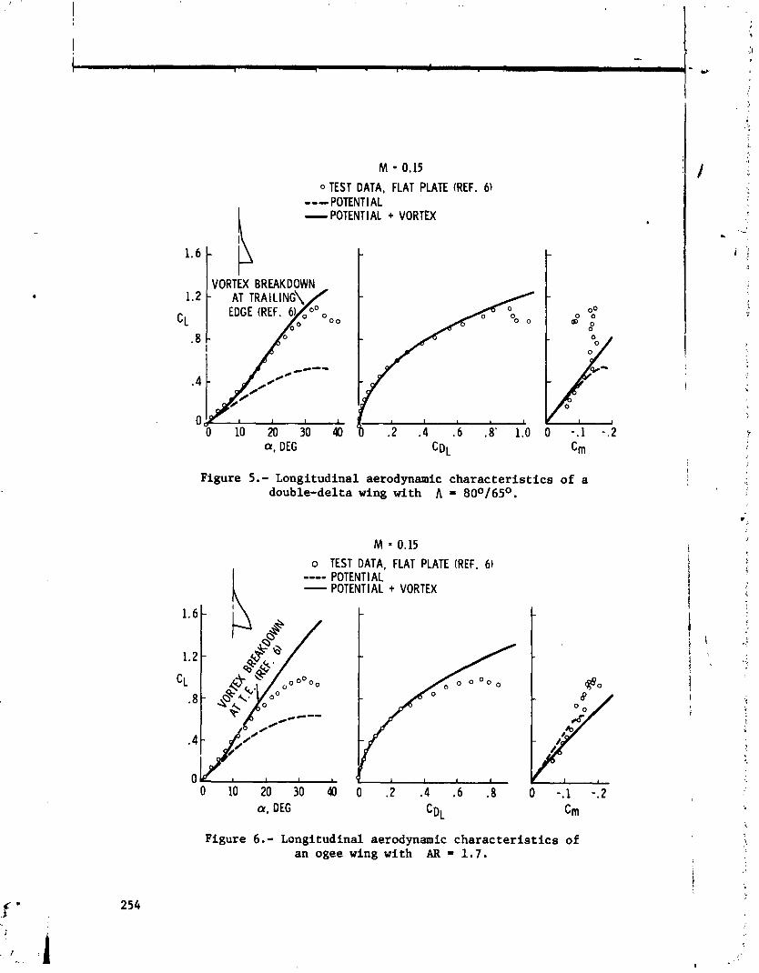
. Comparisons with reference 6 data f o r an 80-165-degree double- de l ta planform and an ogee planform a re presented i n f igures 5 and 6. Excellent agreement with the l i f t and drag predictions i s apparent t o the angle of a t tack f c r vortex breakdown. Good agreement with the pitching moment i s obtained a t the lower angles of a t tack , but the data break away from theory before the angle of a t tack fo r vortex breakdown is reached. This could be caused by a complex flow in terac t ion resu l t ing from the formation of multiple leading-edge vor t ices on t h i s type planform.
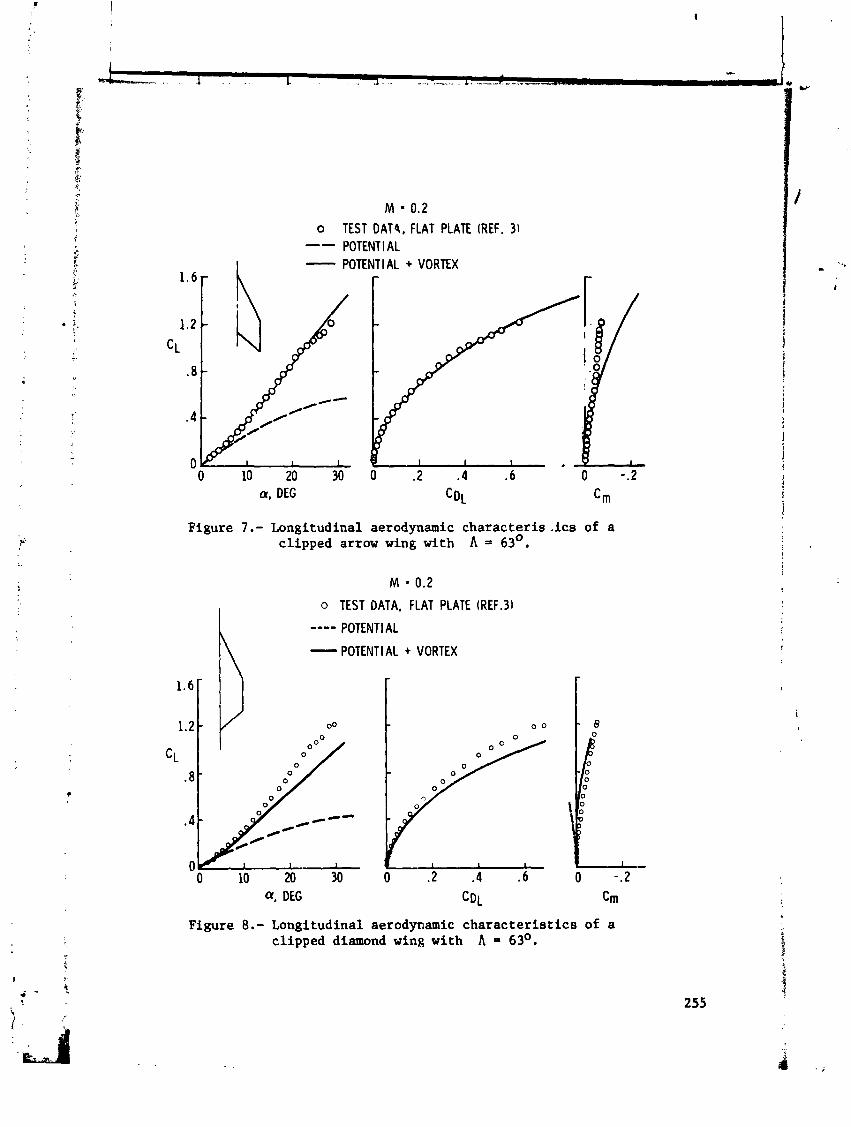
Figures 7 and 8 present t e s t - to- theory comparisons f o r two planforms (reference 3) which help inves t iga te the a b i l i t y of the method to evaluate the e f f e c t s of trail ing-edge sweep. The l i f t of the clipped arrow wing of f igure 7 i s predicted very well , however the l i f t of the clipped diamond wing of f igure 8 i s under-predicted. This i s a t t r ibu ted to the induced l i f t e f f e c t of the shed vo tex on the addi t ional surface area a f t of the t r a i l i n g edge of the diamond wing t i p .
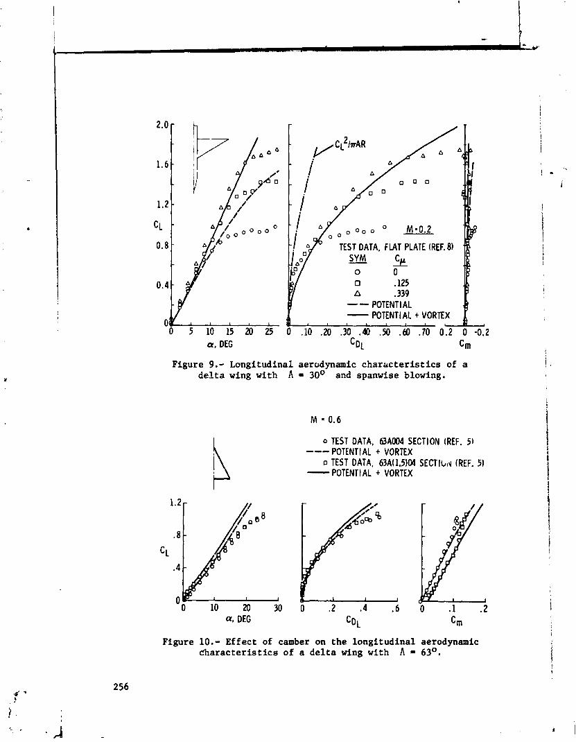
Test data from a model which employs spanwise blowing on the wing upper surface (reference 8) is presented i n f igure 9 f o r a 30-degree dc l t a wing. Comparison with predict ions i l l u s t r a t e s the potent ia l of t h i s method a s a tool f o r estimating the bene- f i t s which can be rea l ized from vortex augmentation of t h i s type. The a b i l i t y of the spanwise blowing t o extend the leading-edge vortex l i f t to higher angles of a t t a c k i s most pronounced. Agree- ment with the predicted l i f t - cu rve slope i s apparent to angles of a t t ack much above the no-blowing vortex breakdown region. There is a blowing-induced camber e f f e c t which i s , of course, not predicted by the theory.
Cambered Wings
The cambered-wing equations havt been used t o predict the charac ter i s t ics of a moderately cambered (C = 0.15) d e l t a wing R i for which reference 5 presents t e s t data. The comparisons of
l i f t , drag, and moment shown i n f igure 10 indica te good agreement. i, The reference 5 data f o r the same wing with an uncambered sect ion : have been included i n f igure 10 t o i l l u s t r a t e the method's a b i l i t y t o predict the incremental camber e f f e c t accurately. It i s a l s o noteworthy tha t the incremental. vor tex- l i f t contr ibut ion due to - camber i s very small. Thus, a t l e a s t f o r small o r moderate amounts of camber, the po ten t i a l flow increment due to camber
1
gives a good approximation f o r the incremental e f f e c t s of camber.
VORTEX-LATTICE ARRANGEMENT FOR THICK WINGS
Vortex-lat t ice methods a re best su i ted f o r the analysis of th in wirgs with sharp leading edges which can be approximated by camber surfaces. The predicted r e s a l t s i n general f o r t h i s type of wing show good agreement with experimental data. How- ever, when the vor tex- la t t ice method i n d i r e c t l y applied to thick wings (including multi-element wings) the cdlculated r e s u l t s do not agree with experimental data.
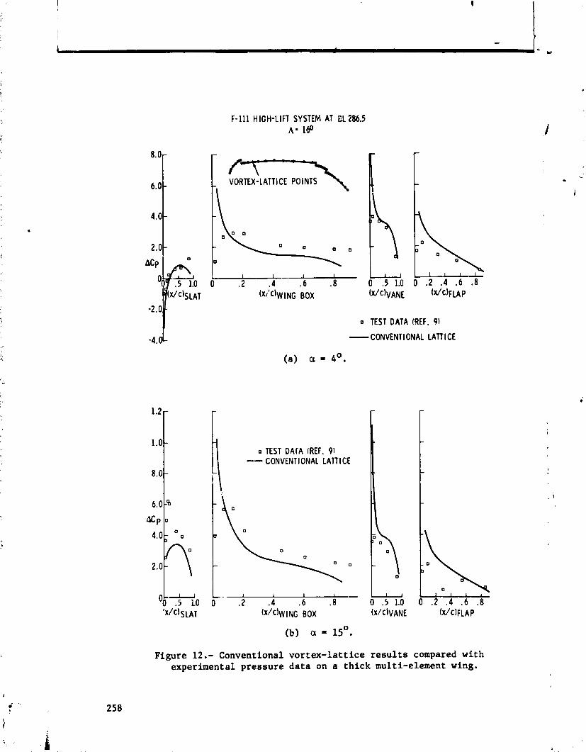
A typica l conventional vor t ex - l a t t i ce layout f o r multi- element wings is s3own i n f igure 11. Each wing element is re- presented by a network of horseshoe vor t ices lying on the camber surface and t r a i l i n g behind the surface. A s can be seer from t h i s f igurz a bound vortex l i e s along the leading edge of each com- ponent of the multi-element system. This causes i n f i ~ i t e ve loc i t i e s t o be generated a t the leading edge which produce very large negative pressure coeff ic ients (unrea l i s t i c ) a t poin ts i n the iamediate v i c i n i t y of the leading edge. This phenomenon i s acceptable f o r t h i n sharp-leading-edge wings but f a i l s t o give acceptable predict ions f o r thick wings. For example, the loads calculated f o r the F-111 wing i n the h i g h - l i f t configuration a t angles of a t tack of 4 and 15 degrees a re compared with experimental data (reference 9) i n f igures 12(a) and 12(b), respect ively. Large discrepancies between experimental and theore t ica l loads a re evident near the leading edge of the wing and f laps .
A technique f o r laying out the l a t t i c e has been developed a t General Dynamics which g rea t ly improves the pressure d i s t r i - butions predicted by the vor tex- la t t ice method f o r thick m u l t i - element wings. A typica l example of t h i s l a t t i c e i s shown i n f igure 13. Each element of the multi-element wing i s represented by a network of horseshoe vor t ices lying on and t r a i l i n g behind a surface which i s composed of the top surface and p a r t of the
bottom surface, and wraps around the leading edge of the wing. The surface on the bottom is extended downstream of the a n t i c i - pated stagnation point . I f the surface i s extended to the t r a i l i n g edge the problem becomes s ingular and meaningless r e s u l t s a re obtained. No large differences i n predicted pressures have been noted fo r var ia t ions i n the extent of the vortex sheet on the lower surface.
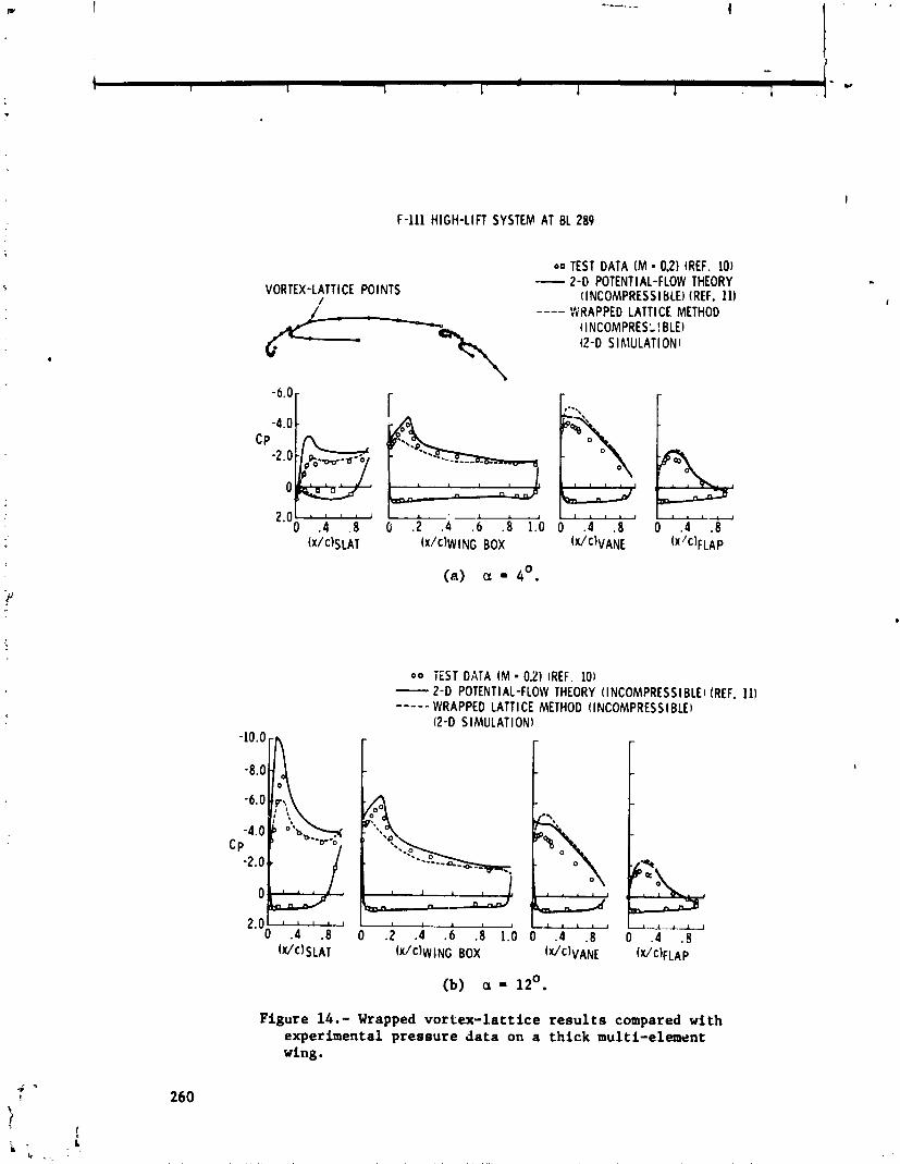
A large-aspect-rat io , unswept, untapered wing having the same sect ion as the F-111 wing sect ion a t BL 289 was analyzed using t h i s wrapped l a t t i c e arrangement. The pressure d i s t r ibu t ions ca l - culated a t the center l ine of t h i s wing a re shown i n f igures 14(a) and 14(b) fo r angles of a t tack of 4 and 12 degrees, respectively. The chordwise d i s t r ibu t ion of the vortex l i n e s is a l s o shown i n these f igures . Since the pressures a t the center l ine of a large- aspect-rat io wing a r e compatible with two-dimensional flow r e s u l t s they a r e compared with two-dimensional experimental data (reference LO) and two-dimensional theore t ica l r e s u l t s (reference 11) i n these f igures . The predict ions show good agreement with both the experimental and theore t i ca l r e s u l t s . The two-dimensional theore t ica l pressure d i s t r ibu t ions shown were obtained with a much denser chordwise d i s t r i b u t i o n of points . A b e t t e r predict ion should be obtained with the vor tex - l a t t i ce method i f a denser chordwise portioning of the l a t t i c e i s employed.
CONCLUDING REMARKS
A method has been formulated f o r determining the l i f t , zero- leading-edge-suction drag due t o l i f t , and pi tching moment of th in , sharp-edged, low-aspect-ratio wings with camber. This method u t i l i z e s a vor tex- la t t ice procedure modified to include v o r t e x - l i f t induced e f f e c t s by including an extension of the Polhamus suction-analogy concept. Good agreement with experiment i s obtained for simple highly swept planforms below the angle of a t t ack a t which vortex breakdown reaches the t r a i l i n g edge of the wing and a t somewhat lower angles of a t tack f o r wings with more complex flow pat te rns , such as double-delta and ogee planforms.
The method shows promise as a tool fo r evaluation of the po ten t i a l of vortex augmentation systems.
To obtain more accurate predictions fo r :he more complex planforms, i t i s necessary t o include the e f f e c t s of the
- Y
t .
1 !
h
progression of the vor t ices away from the leading edge and t i p of the planform and t o include the vortex in terac t ions on plan- forms which emanate multiple leading-edge vor t i ces , 1
A method has a l s o been developed f o r laying out the vortex l a t t i c e f o r th ick multi-element wings which gives accurate pressure predict ions on the top and pa r t of the bottom surface - of the wing. Comparison with experimental data and other 1
theore t ica l methods subs tant ia tes the accuracy of the r e s u l t s .
REFERENCES
1. Poihamus, E. C. : Predictions of Vortex-Lift Charac ter i s t ics by a Leading-Edge Suction Analogy. Journal of Ai rc ra f t , volume 8, no. 4, April 1971, pp. 193-199.
2. Polhamus, E. C. : A Concept of the Vortex L i f t of Sharp-Edge Delta Wings Based on a Leading-Edge Suction Analogy. NASA TN D-3767, December 1966.
3. Lamar, J. E. : Extension of Leading-Edge-Suction Analogy t o Wings with Separated Flow Around the Side Edges a t Subsonic Speeds. NASA TR R-428, October 1974.
4. Bradley, R. G. ; Smith, C. W. ; and Bhateley, I. C. : Vortex- L i f t Prediction f o r Complex Wing Planforms . Journal of <
Aircraf t , volume 10, no. 6, June 1973, pp. 379-381.
5. Emerson, H. F.: Wind-Tunnel Investigat'on of the Effect of , ,
Clipping the Tips of Triangular Wings 0.' I f f e ren t Thickness, Camber, and Aspect Ratio - Transonic Bun, iqethod. NACA TN 3671, June 1956.
6. Wentz, W. H. , Jr. ; and Kohlman, D. L. : Wind Tunnel Inves t i - gations of Vortex Breakdown on Slender Sharp-Edged Wings. NASA CR-98737, November 1968.
7. Nelson, W. H. ; and McDevitt, J. B. : The Transonic Charac- t e r i s t i c s of 22 Rectangular, Symmetrical Wing Models of Varying Aspect Ratio and Thickness. NACA TN 3501, June 1955.
8. Bradley, R. G . ; Wray, W. 0.; Smith, C. W . : An Experimental Investigation of Leading-Edge Vortex Augmentation by Blowing. NASA CR-132415, 1 April 1974.
Goss, W. J .: Report of Fourth Ser ies Wind Tunnel Tests of 1 the 116-scale F-111 Semi-span lbde l . Grumman Aircraf t Report i
GW.TT 184 (310-4), October 1963.
Goodwin, L. C. : Wind Tbnnel Tests on a 2-D Model of a NACA - . . +
64A210 (bbdified) Section with Various Leading and Trai l ing Edge Devices, Using the Canadair 2-D Blowing Walls, i n the NAE 6x9-Ft Low-Speed Wind Tunnel, NAE Test 6x910140, D I R
I
Project All-Phase 11, volumes 1, 2, and 3. Canadair Report ERR-CL-RAA-228-010, Sept. 1969.
Bhateley, I. C. : Invest igat ion of Inviscid Incompressible i
Flow, Part I V : Potent ia l Flow Analysis about Arbitrary : Elultiple Two-Dimensional Bodies by the Method of Distributed Singular i t ies . General Dynamics Fort Worth Division Report ERR-FW-669, 31 March 1968.
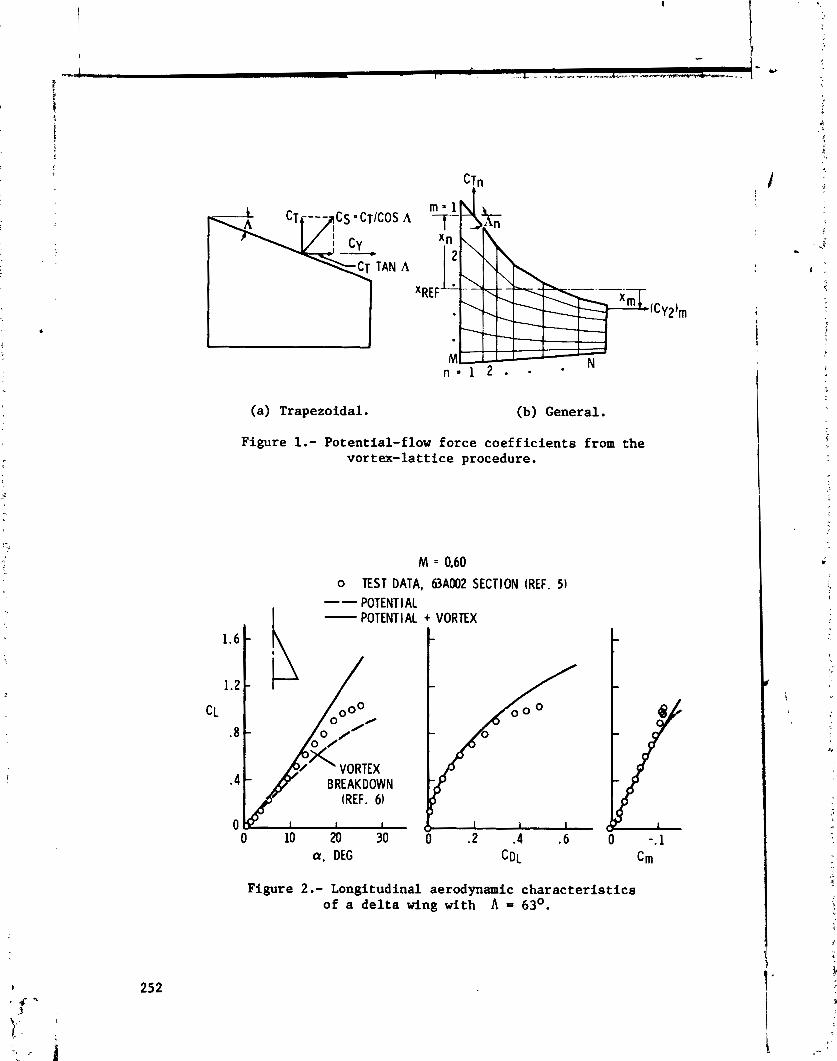
(a) Trapezoidal. (b) General.
Figure 1.- Potential-flow force coefficients from the vortex-lattice procedure.
o TEST DATA, 63A002 SECTION (REF. 5) -- I
POTENT l AL - POTENTIAL + VORTEX
a, DEG
Figure 2.- Longitudinal aerodynamic characteristics of a delta wing with A = 63O.
M = 0.60 OTEST DATA, 63A002 SECTION (REF. 5 ) --- POTENT l AL - POTENTI AL + VORTEX
0 10 M 30 0 . 2 .4 .6 0 -.l
Figure 3.- Longitudinal aerodynamic characterist ics of a clipped de l ta wing with A = 63O and h = 0.4.
Figure 4.- Longitudinal aerodynamic characterist ics of a rectangular wing with AR = 2 . 0 .
M 0.40 0 TEST DATA, 63A002 SECTIOFI (REF. 7 ) -- POTENT I AL -
I POTENTIAL + VORTEX
TEST DATA, FLAT PLATE (REF. 6 ) --- POTENTIAL - POTENTIAL + VORTEX
0 0
-c--
1 1 1 1
0 10 20 30 40 a, DEG
Figure 5.- Longitudinal aerodynamic characteristics of a -
double-delta wing A t h A = 800165O.
o TEST DATA, FLAT PLATE (REF. 6 ) ---- POTENT1 AL - POTENTIAL + VORTEX
a, DEG C~~
Figure 6.- Longitudinal aerodynamic characteristics of an ogee wing with AR = 1.7.
M = 0.2 TEST DAT4, FLAT PLATE (REF. 31 POTENTI AL POTENTIAL + VORTEX
a. DEG
Figure 7.- Longitudinal aerodynamic characteris-ics of a clipped arrow wing with = 63O.
M = 0.2
h o TEST DATA, FLAT PLATE (REF.31
---- POTENT1 AL
- POTENTI AL + VORTEX
Figure 8.- Longitudinal aerodynamic characteristics of a clipped diamond wing with A = 6 3 O .
a, DEG
Figure 9.- Longitudinal aerodynamic characteristics of a delta wing with A = 30° and spanwise blowing.
o TEST DATA, 63A004 SECTION (REF. 51 --- POTENTIAL + VORTEX o TEST DATA, 63A(1.5)04 SECTIbtd (REF. 5 ) - POTENTIAL + VORTEX
Figure 10.- Effect of camber on the longitudinal aerodynamic characteristics of a delta wing with A = 63O.
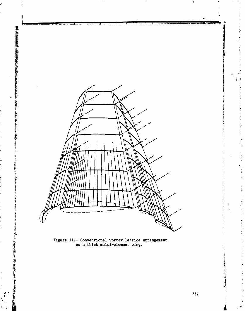
Figure 11.- Conventional vortex-lattice arrangement on a thick multi-element wing.
F-111 HIGH-LIFT SYSTEM AT BL 286.5 A - 160
(a) a = 4'.
o TEST DArA (REF. 91 - CONVENTIONAL LATTl CE
-
IY
-
0 TEST DATA (REF. 91
- CONVENTIONAL LATTl CE
Figure 12.- Conventional vortex-lattice results compared with experimental pressure data on a thick multi-element wing.
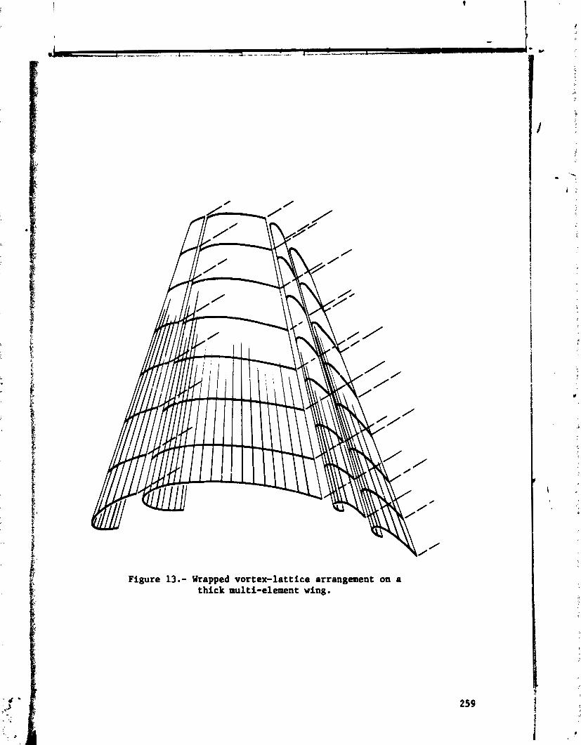
Figure 13.- Wrapped vortex-lattice arrangement on a thick multi-element wing.
F-111 HIGH-LIFT SYSTEM AT 8 1 289
VORTEX-LATTI CE POINTS I
00 TEST DATA ( M = 0.2) (REF. 10) -- 2-0 POTENTI AL-FLOW THEORY (INCOMPRESSI BLEI (REF. 11) ---- WRAPPED LATTICE METHOD (INCOMPRES: I BLE) (2 -0 SIMULATIONI
(a) a = 4'.
0 0 iEST DATA ( M = 0.21 (REF. 101 - 2 - 0 POTENTIAL-FLOW THEORY (INCOMPRESS1 BLEI (REF. 111 ----- WRAPPED LATTl CE METHOD (INCOMPRESS I BLEI
(2-D SIMULATIONI
(b) a = 12'.
Figure 14.- Wrapped vortex-lattice results compared with experimental pressure data on a thick multi-element wing.