Embed Size (px)
Citation preview
AERO-STRUCTURAL WING PLANFORM
OPTIMIZATION
Kasidit Leoviriyakitand
Antony Jameson
Department of Aeronautics and Astronautics
Stanford University, Stanford, CA
45 th Aero/Astro Industrial Affiliates MeetingStanford, April 27-28, 2004
c© K. Leoviriyakit & A. Jameson 2004 1/15 Aero-Structural Wing Planform Optimization
+ Introduction and Motivation
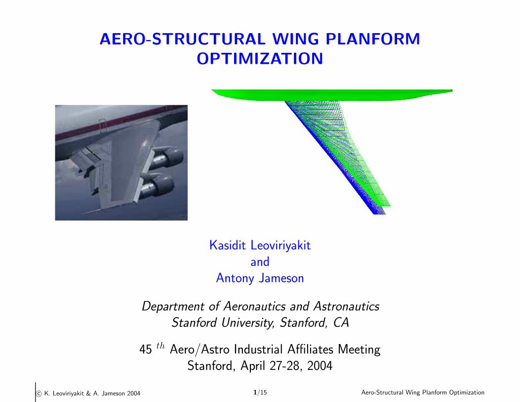
ã Shock drag and vortex drag are the major fraction of the total drag of thelong-rang transport aircraft.
ã Boeing 747 at CL ∼ .47 (including fuselage lift ∼ 15 %)
Item CD Cumulative CD
Wing pressure 120 counts 120 counts(15 shock,105 vortex)
Wing friction 45 165Fuselage 50 215
Tail 20 235Nacelles 20 255
Other 15 270—
Total 270
ã During the last decade aerodynamic shape optimization methods based oncontrol theory have been used to design shock free wings and the methods areperfected for rigid wings with fixed planforms.
ã Wing planform modifications can also reduce vortex drag.
c© K. Leoviriyakit & A. Jameson 2004 2/15 Aero-Structural Wing Planform Optimization
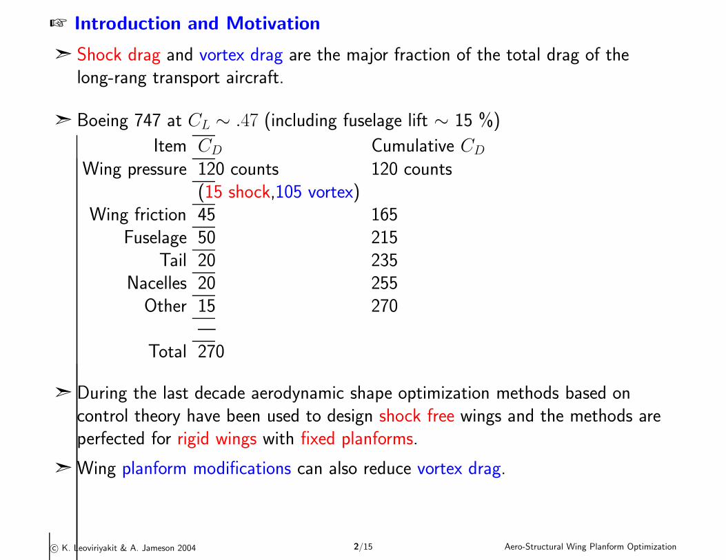
+ Re-design for a shock free wing using adjoint method
SYMBOL
SOURCE SYN88 DESIGN 17SYN88 DESIGN 0
CL 0.420 0.420
CD 0.00939 0.01077
COMPARISON OF CHORDWISE PRESSURE DISTRIBUTIONSBOEING 747 WING-BODY
REN = 0.00 , MACH = 0.870 , ALPHA = 2.20
Kasidit Leoviriyakit21:03 Thu
1 Jan 04COMPPLOT
JCV 1.13COMPPLOT
JCV 1.13COMPPLOT
JCV 1.13COMPPLOT
JCV 1.13COMPPLOT
JCV 1.13COMPPLOT
JCV 1.13COMPPLOT
JCV 1.13COMPPLOT
JCV 1.13COMPPLOT
JCV 1.13COMPPLOT
JCV 1.13
Solution 1 Upper-Surface Isobars
( Contours at 0.05 Cp )
0.2 0.4 0.6 0.8 1.0
-1.5
-1.0
-0.5
0.0
0.5
1.0
Cp
X / C 11.7% Span
0.2 0.4 0.6 0.8 1.0
-1.5
-1.0
-0.5
0.0
0.5
1.0
Cp
X / C 31.6% Span
0.2 0.4 0.6 0.8 1.0
-1.5
-1.0
-0.5
0.0
0.5
1.0
Cp
X / C 50.4% Span
0.2 0.4 0.6 0.8 1.0
-1.5
-1.0
-0.5
0.0
0.5
1.0
Cp
X / C 70.0% Span
0.2 0.4 0.6 0.8 1.0
-1.5
-1.0
-0.5
0.0
0.5
1.0
Cp
X / C 89.8% Span
ã Modify Sections and Fix Planform.
ã Result: Shock free wing (6% airplane-drag reduction) within 5 minutes(using 1 1.7 gHz processor).
c© K. Leoviriyakit & A. Jameson 2004 3/15 Aero-Structural Wing Planform Optimization
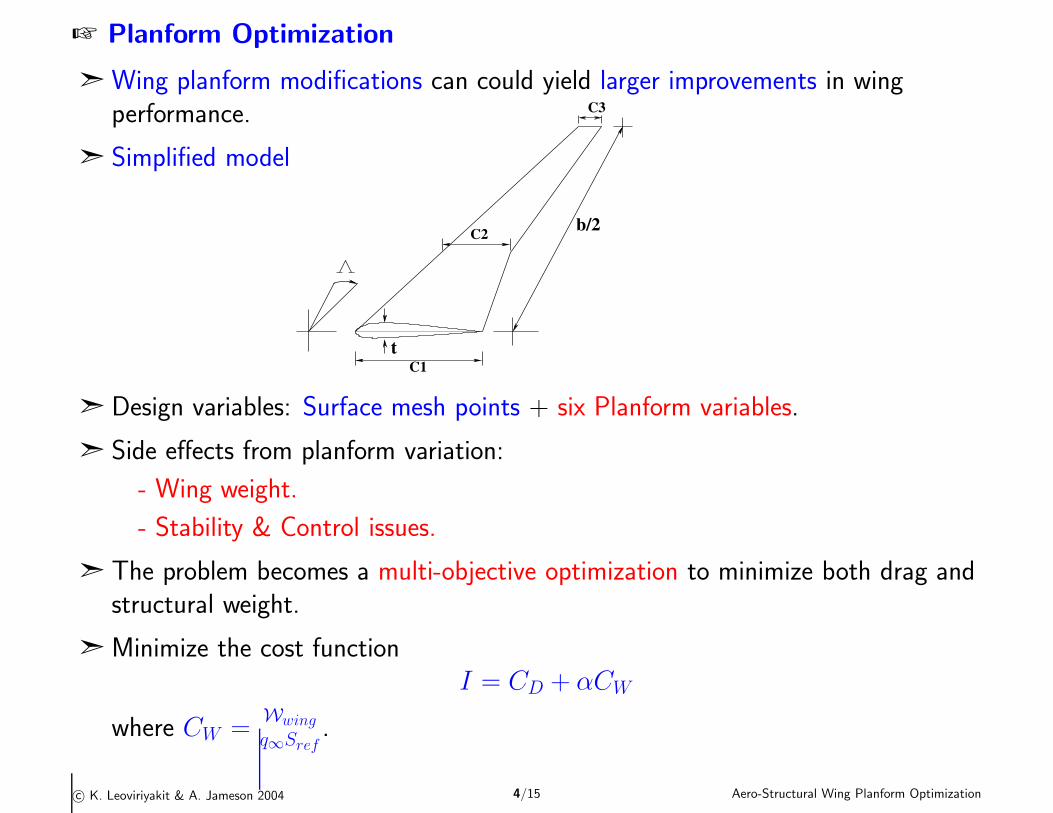
+ Planform Optimization
ã Wing planform modifications can could yield larger improvements in wingperformance.
ã Simplified model
t
b/2C2
C3
C1
ã Design variables: Surface mesh points + six Planform variables.
ã Side effects from planform variation:
- Wing weight.
- Stability & Control issues.
ã The problem becomes a multi-objective optimization to minimize both drag andstructural weight.
ã Minimize the cost functionI = CD + αCW
where CW =Wwing
q∞Sref.
c© K. Leoviriyakit & A. Jameson 2004 4/15 Aero-Structural Wing Planform Optimization
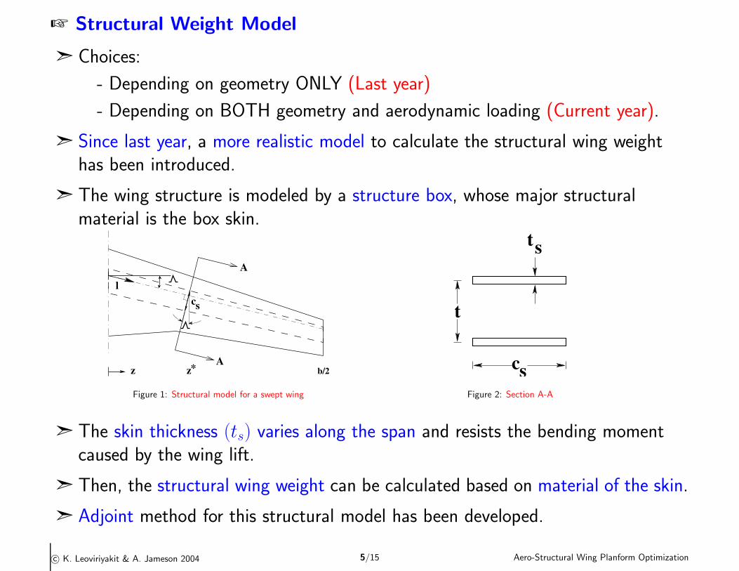
+ Structural Weight Model
ã Choices:
- Depending on geometry ONLY (Last year)
- Depending on BOTH geometry and aerodynamic loading (Current year).
ã Since last year, a more realistic model to calculate the structural wing weighthas been introduced.
ã The wing structure is modeled by a structure box, whose major structuralmaterial is the box skin.
l
A
Ab/2
sc
*zz
Figure 1: Structural model for a swept wing
t
cs
ts
Figure 2: Section A-A
ã The skin thickness (ts) varies along the span and resists the bending momentcaused by the wing lift.
ã Then, the structural wing weight can be calculated based on material of the skin.
ã Adjoint method for this structural model has been developed.
c© K. Leoviriyakit & A. Jameson 2004 5/15 Aero-Structural Wing Planform Optimization
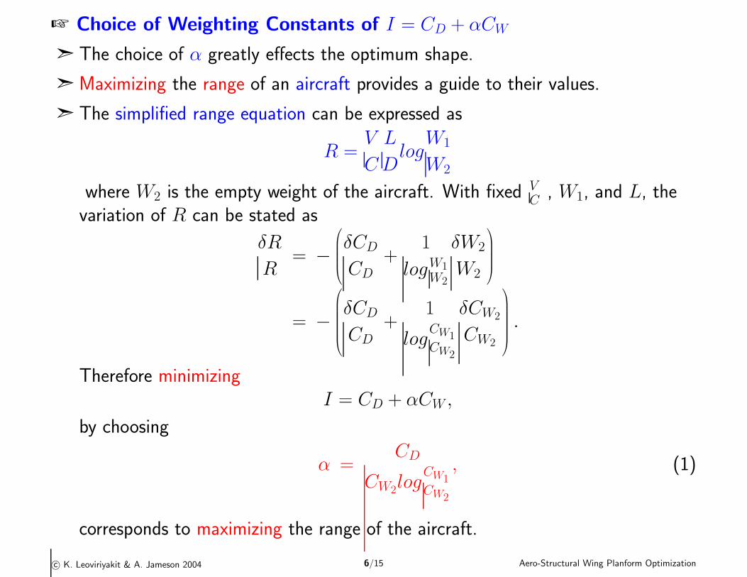
+ Choice of Weighting Constants of I = CD + αCW
ã The choice of α greatly effects the optimum shape.
ã Maximizing the range of an aircraft provides a guide to their values.
ã The simplified range equation can be expressed as
R =V
C
L
Dlog
W1
W2
where W2 is the empty weight of the aircraft. With fixed VC
, W1, and L, thevariation of R can be stated as
δR
R= −
δCD
CD
+1
logW1
W2
δW2
W2
= −
δCD
CD
+1
logCW1
CW2
δCW2
CW2
.
Therefore minimizingI = CD + αCW ,
by choosing
α =CD
CW2log
CW1
CW2
, (1)
corresponds to maximizing the range of the aircraft.
c© K. Leoviriyakit & A. Jameson 2004 6/15 Aero-Structural Wing Planform Optimization
+ Sample of Planform Optimization
ã Test case: Boeing 747 wing-fuselage and modified geometries at the followingflow conditions
M∞ = 0.87
CL = 0.42 (fixed)
Choose α3 according to (1) to maximize range.
ã Test case: MD 11 wing-fuselage and modified geometries at the following flowconditions
M∞ = 0.83
CL = 0.50 (fixed)
Choose α3 according to (1) to maximize range.
c© K. Leoviriyakit & A. Jameson 2004 7/15 Aero-Structural Wing Planform Optimization
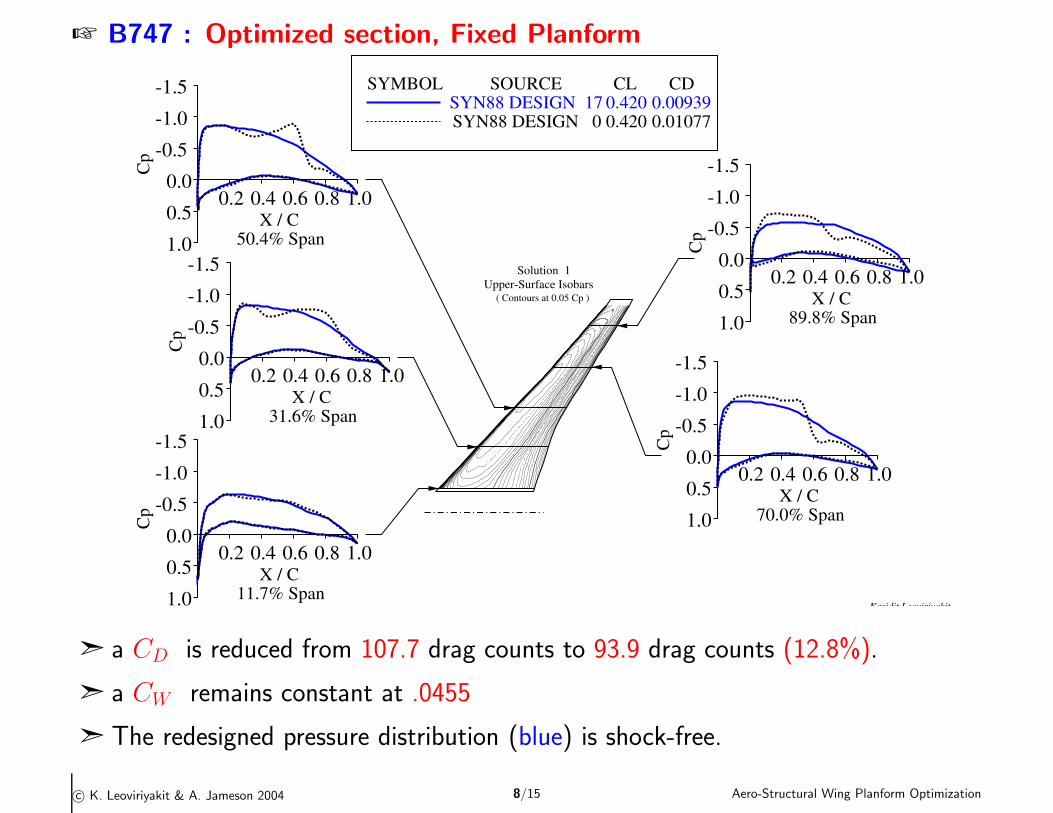
+ B747 : Optimized section, Fixed Planform
SYMBOL
SOURCE SYN88 DESIGN 17SYN88 DESIGN 0
CL 0.420 0.420
CD 0.00939 0.01077
COMPARISON OF CHORDWISE PRESSURE DISTRIBUTIONSBOEING 747 WING-BODY
REN = 0.00 , MACH = 0.870 , ALPHA = 2.20
Kasidit Leoviriyakit21:03 Thu
1 Jan 04COMPPLOT
JCV 1.13COMPPLOT
JCV 1.13COMPPLOT
JCV 1.13COMPPLOT
JCV 1.13COMPPLOT
JCV 1.13COMPPLOT
JCV 1.13COMPPLOT
JCV 1.13COMPPLOT
JCV 1.13COMPPLOT
JCV 1.13COMPPLOT
JCV 1.13
Solution 1 Upper-Surface Isobars
( Contours at 0.05 Cp )
0.2 0.4 0.6 0.8 1.0
-1.5
-1.0
-0.5
0.0
0.5
1.0
Cp
X / C 11.7% Span
0.2 0.4 0.6 0.8 1.0
-1.5
-1.0
-0.5
0.0
0.5
1.0
Cp
X / C 31.6% Span
0.2 0.4 0.6 0.8 1.0
-1.5
-1.0
-0.5
0.0
0.5
1.0
Cp
X / C 50.4% Span
0.2 0.4 0.6 0.8 1.0
-1.5
-1.0
-0.5
0.0
0.5
1.0
Cp
X / C 70.0% Span
0.2 0.4 0.6 0.8 1.0
-1.5
-1.0
-0.5
0.0
0.5
1.0
Cp
X / C 89.8% Span
ã a CD is reduced from 107.7 drag counts to 93.9 drag counts (12.8%).
ã a CW remains constant at .0455
ã The redesigned pressure distribution (blue) is shock-free.
c© K. Leoviriyakit & A. Jameson 2004 8/15 Aero-Structural Wing Planform Optimization
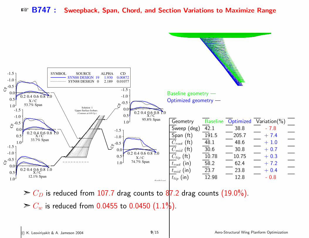
+ B747 : Sweepback, Span, Chord, and Section Variations to Maximize Range
Baseline geometry —
Optimized geometry —
Geometry Baseline Optimized Variation(%)Sweep (deg) 42.1 38.8 - 7.8
Span (ft) 191.5 205.7 + 7.4Croot (ft) 48.1 48.6 + 1.0
Cmid (ft) 30.6 30.8 + 0.7Ctip (ft) 10.78 10.75 + 0.3
troot (in) 58.2 62.4 + 7.2tmid (in) 23.7 23.8 + 0.4
ttip (in) 12.98 12.8 - 0.8
SYMBOL
SOURCE SYN88 DESIGN 19SYN88 DESIGN 0
ALPHA 1.930 2.189
CD 0.00872 0.01077
COMPARISON OF CHORDWISE PRESSURE DISTRIBUTIONSBOEING 747 WING-BODY
REN = 0.00 , MACH = 0.870 , CL = 0.420
Kasidit Leoviriyakit20:48 Thu
1 Jan 04COMPPLOT
JCV 1.13COMPPLOT
JCV 1.13COMPPLOT
JCV 1.13COMPPLOT
JCV 1.13COMPPLOT
JCV 1.13COMPPLOT
JCV 1.13COMPPLOT
JCV 1.13COMPPLOT
JCV 1.13COMPPLOT
JCV 1.13COMPPLOT
JCV 1.13
Solution 1 Upper-Surface Isobars
( Contours at 0.05 Cp )
0.2 0.4 0.6 0.8 1.0
-1.5
-1.0
-0.5
0.0
0.5
1.0
Cp
X / C 12.1% Span
0.2 0.4 0.6 0.8 1.0
-1.5
-1.0
-0.5
0.0
0.5
1.0
Cp
X / C 33.7% Span
0.2 0.4 0.6 0.8 1.0
-1.5
-1.0
-0.5
0.0
0.5
1.0
Cp
X / C 53.7% Span
0.2 0.4 0.6 0.8 1.0
-1.5
-1.0
-0.5
0.0
0.5
1.0
Cp
X / C 74.7% Span
0.2 0.4 0.6 0.8 1.0
-1.5
-1.0
-0.5
0.0
0.5
1.0C
pX / C
95.8% Span
ã CD is reduced from 107.7 drag counts to 87.2 drag counts (19.0%).
ã Cw is reduced from 0.0455 to 0.0450 (1.1%).
c© K. Leoviriyakit & A. Jameson 2004 9/15 Aero-Structural Wing Planform Optimization
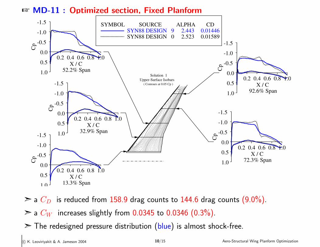
+ MD-11 : Optimized section, Fixed Planform
SYMBOL
SOURCE SYN88 DESIGN 9SYN88 DESIGN 0
ALPHA 2.443 2.523
CD 0.01446 0.01589
COMPARISON OF CHORDWISE PRESSURE DISTRIBUTIONSMD-11 WING/BODY + 4.5FT WINGTIP EXTREN = 0.00 , MACH = 0.830 , CL = 0.500
Kasidit Leoviriyakit21:18 Thu25 Mar 04
COMPPLOTJCV 1.13
COMPPLOTJCV 1.13
COMPPLOTJCV 1.13
COMPPLOTJCV 1.13
COMPPLOTJCV 1.13
COMPPLOTJCV 1.13
COMPPLOTJCV 1.13
COMPPLOTJCV 1.13
COMPPLOTJCV 1.13
COMPPLOTJCV 1.13
Solution 1 Upper-Surface Isobars
( Contours at 0.05 Cp )
0.2 0.4 0.6 0.8 1.0
-1.5
-1.0
-0.5
0.0
0.5
1.0
Cp
X / C 13.3% Span
0.2 0.4 0.6 0.8 1.0
-1.5
-1.0
-0.5
0.0
0.5
1.0
Cp
X / C 32.9% Span
0.2 0.4 0.6 0.8 1.0
-1.5
-1.0
-0.5
0.0
0.5
1.0
Cp
X / C 52.2% Span
0.2 0.4 0.6 0.8 1.0
-1.5
-1.0
-0.5
0.0
0.5
1.0
Cp
X / C 72.3% Span
0.2 0.4 0.6 0.8 1.0
-1.5
-1.0
-0.5
0.0
0.5
1.0
Cp
X / C 92.6% Span
ã a CD is reduced from 158.9 drag counts to 144.6 drag counts (9.0%).
ã a CW increases slightly from 0.0345 to 0.0346 (0.3%).
ã The redesigned pressure distribution (blue) is almost shock-free.
c© K. Leoviriyakit & A. Jameson 2004 10/15 Aero-Structural Wing Planform Optimization
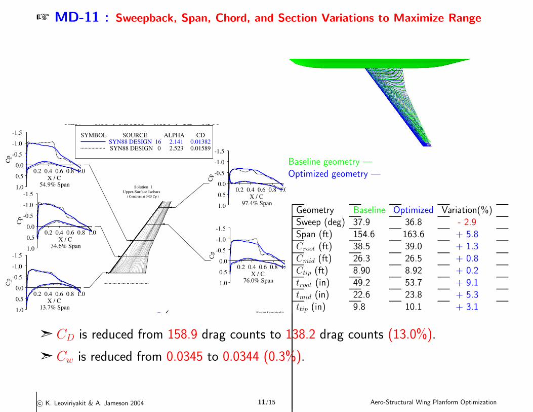
+ MD-11 : Sweepback, Span, Chord, and Section Variations to Maximize Range
Baseline geometry —
Optimized geometry —
Geometry Baseline Optimized Variation(%)Sweep (deg) 37.9 36.8 - 2.9
Span (ft) 154.6 163.6 + 5.8Croot (ft) 38.5 39.0 + 1.3
Cmid (ft) 26.3 26.5 + 0.8Ctip (ft) 8.90 8.92 + 0.2
troot (in) 49.2 53.7 + 9.1tmid (in) 22.6 23.8 + 5.3
ttip (in) 9.8 10.1 + 3.1
SYMBOL
SOURCE SYN88 DESIGN 16SYN88 DESIGN 0
ALPHA 2.141 2.523
CD 0.01382 0.01589
COMPARISON OF CHORDWISE PRESSURE DISTRIBUTIONSMD-11 WING/BODY + 4.5FT WINGTIP EXTREN = 0.00 , MACH = 0.830 , CL = 0.500
Kasidit Leoviriyakit20:34 Fri
26 Mar 04COMPPLOT
JCV 1.13COMPPLOT
JCV 1.13COMPPLOT
JCV 1.13COMPPLOT
JCV 1.13COMPPLOT
JCV 1.13COMPPLOT
JCV 1.13COMPPLOT
JCV 1.13COMPPLOT
JCV 1.13COMPPLOT
JCV 1.13COMPPLOT
JCV 1.13MCDONNELL DOUGLAS
Solution 1 Upper-Surface Isobars
( Contours at 0.05 Cp )
0.2 0.4 0.6 0.8 1.0
-1.5
-1.0
-0.5
0.0
0.5
1.0
Cp
X / C 13.7% Span
0.2 0.4 0.6 0.8 1.0
-1.5
-1.0
-0.5
0.0
0.5
1.0
Cp
X / C 34.6% Span
0.2 0.4 0.6 0.8 1.0
-1.5
-1.0
-0.5
0.0
0.5
1.0
Cp
X / C 54.9% Span
0.2 0.4 0.6 0.8 1.0
-1.5
-1.0
-0.5
0.0
0.5
1.0
Cp
X / C 76.0% Span
0.2 0.4 0.6 0.8 1.0
-1.5
-1.0
-0.5
0.0
0.5
1.0C
p
X / C 97.4% Span
ã CD is reduced from 158.9 drag counts to 138.2 drag counts (13.0%).
ã Cw is reduced from 0.0345 to 0.0344 (0.3%).
c© K. Leoviriyakit & A. Jameson 2004 11/15 Aero-Structural Wing Planform Optimization
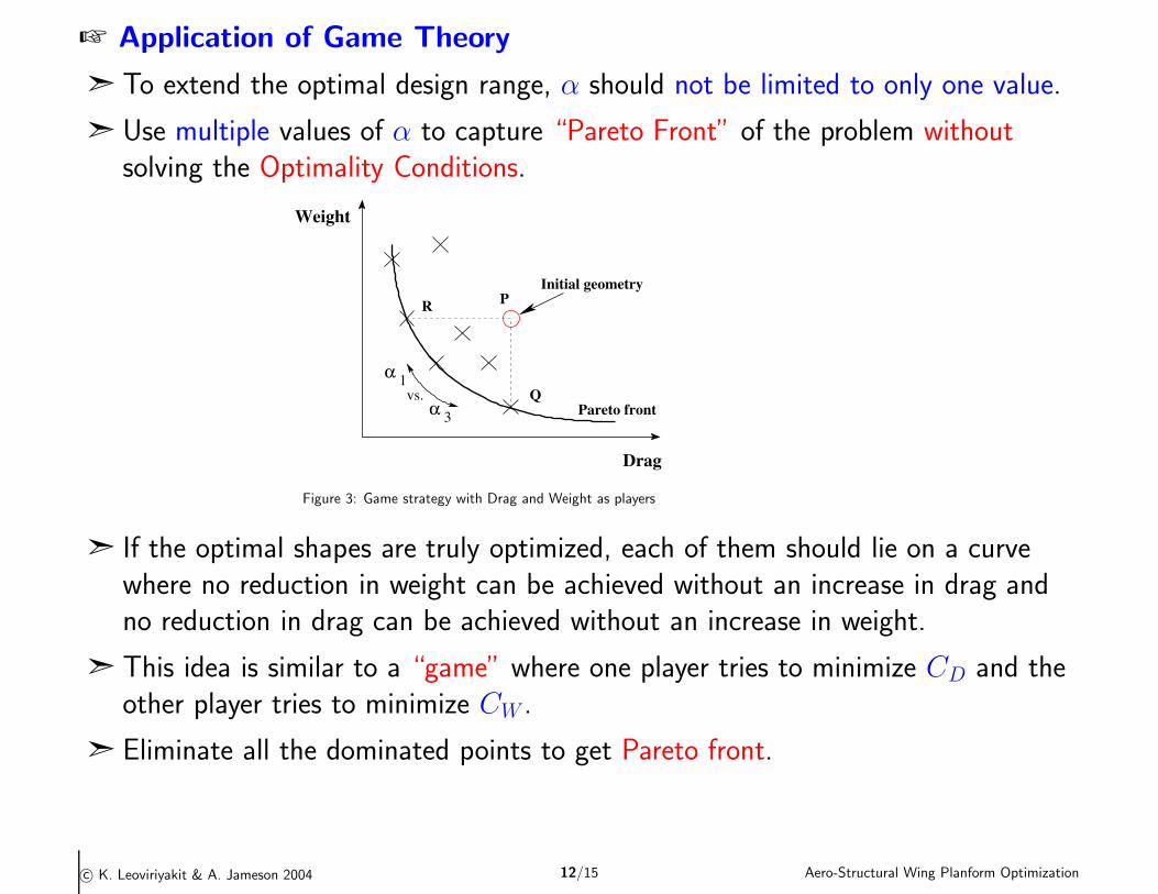
+ Application of Game Theory
ã To extend the optimal design range, α should not be limited to only one value.
ã Use multiple values of α to capture “Pareto Front” of the problem withoutsolving the Optimality Conditions.
Drag
PInitial geometry
QPareto front
vs.
R
Weight
α 1
α 3
Figure 3: Game strategy with Drag and Weight as players
ã If the optimal shapes are truly optimized, each of them should lie on a curvewhere no reduction in weight can be achieved without an increase in drag andno reduction in drag can be achieved without an increase in weight.
ã This idea is similar to a “game” where one player tries to minimize CD and theother player tries to minimize CW .
ã Eliminate all the dominated points to get Pareto front.
c© K. Leoviriyakit & A. Jameson 2004 12/15 Aero-Structural Wing Planform Optimization
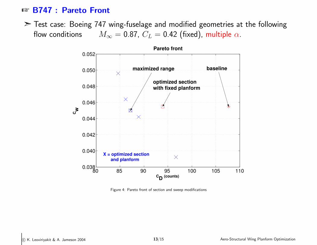
+ B747 : Pareto Front
ã Test case: Boeing 747 wing-fuselage and modified geometries at the followingflow conditions M∞ = 0.87, CL = 0.42 (fixed), multiple α.
80 85 90 95 100 105 1100.038
0.040
0.042
0.044
0.046
0.048
0.050
0.052
CD (counts)
Cw
Pareto front
baseline
optimized section with fixed planform
X = optimized section and planform
maximized range
Figure 4: Pareto front of section and sweep modifications
c© K. Leoviriyakit & A. Jameson 2004 13/15 Aero-Structural Wing Planform Optimization
+ Conclusions
ã By exploring the adjoint method, it is possible to carry out vary rapid wingoptimization for preliminary design. (even on laptop computer)
ã Case studies of wing planform optimization of long range transport aircraftsuggest the possibility of extending the attainable lift-to-drag ratio versus Machnumber significantly beyond historical trends.
ã The results indicate that by stretching the span together with decreasing sweepand thickening the wing sections, the lift-to-drag ratio can be increased withoutany penalty on the structure weight.
ã The intelligent use of optimization techniques may ultimately have an evengreater impact by enabling the exploration of radical departures fromconventional design.
ã The application of game theory provides insight into how to combine drag andwing weight in the cost function, broadening the design range of optimal shapes
c© K. Leoviriyakit & A. Jameson 2004 14/15 Aero-Structural Wing Planform Optimization
+ Acknowledgment
This work has benefited greatly from the support of the Air Force Office ofScience Research under grant No. AF F49620-98-1-2002.
c© K. Leoviriyakit & A. Jameson 2004 15/15 Aero-Structural Wing Planform Optimization


![Airport2030 M Family Concepts of Box Wing 12-08-10€¦ · Intern at Aero – Aircraft Design and Aero ... [Raymer 1992] however the ... With the box wing aircraft,](https://img.pdfslide.us/doc/110x75/5b87c7657f8b9aa0218d82b2/airport2030-m-family-concepts-of-box-wing-12-08-10-intern-at-aero-aircraft.jpg)