Embed Size (px)
Citation preview

FT-8 MobilePac 60Hz/50hz Technical Notes

FT-8 MobilePac: 60Hz-13.8kV, Liquid Fuel WI-42 & DRY Notes Applicable to Performance and Emissions Data Standard MobilePac Performance, Sea Level, 60% RH
CustCpy_StdMP_60-138_LF_MJ_R2-090911.xls
W A R N IN G -- T h i s d o c u m e n t c o n ta in s t e c h n ic a l d a ta t h e e x p o r t o f w h i c h is o r m a y b e r e s tr ic te d b y t h e E x p o r t A d m in i s tra ti o n A c t a n d th e E x p o r t A d m in is t ra ti o n R e g u la t io n s ( E A R ) , 1 5 C .F .R . p a r t s 7 3 0 -7 7 4 . D i ve r s io n c o n t r a r y to U . S . la w is pr o h i b i te d . T h e e x p o r t, re e xp o r t , t ra ns f e r o r r e - t ra n s f e r o f th is te c h n ic a l d a t a to a n y o th e r c o m p a n y , e n t it y , p e rs o n, o r d e s ti na t io n , o r fo r a n y u s e o r p u r p o s e o t he r th a n th a t f o r w h ic h th e te c h n ic a l da ta w a s o r i g i n a l ly pr o v i d e d b y P & W , i s p r o hi b ite d w it h o u t pr io r w r i t te n a p p r o v a l f ro m P & W a n d a u t h o r iz a tio n u n de r a p p l ic a b le e x p o r t c o nt r o l la w s .
E A R E x p o r t C la s s if ic a ti o n : E C C N 9 E 9 9 1
Notes:
0. All Performance/Emissions Data submitted are subject to the sum of the following notes, and the most recent version of PWPS "Factory and Field Tests" at the time of the proposal offering. Notes included herein shall supersede any notes in the Contract, Specifications, Terms & Conditions to the contrary; and shall have the highest level of hierarchy in all related documents.
1. All data is presented on an estimated basis. Should a job progress to needing guaranteed values, then customer/site specific performance shall be issued, with appropriate guarantee margins added. In addition, the following notes are being presented as our customary practices related to performance and emissions guarantees.
2. The minimum operating compressor inlet temperature for the MobilePac is -58 deg F.
3. The minimum operating temperature the MobilePac package can be operated in is -40 deg F.
4. The MobilePac consists of one turbine (1-GT) driving one generator. Rates are shown as per MP. 5. Liquid fuel supplied to gas turbines must meet PWPS fuel specification FR-1. 6. Water used for burner injection must meet PWPS specification AR-1 (demin water). 7. DRY performance data is based on the standard combustor without water injection. 8. Water injected data is shown for liquid fuel WI-42 ppmvd NOx @ 15% O2. 9. All emission concentration data (ppmvd and/or mg/Nm3) are corrected to 15% O2, on a dry basis. 10. All data supplied based on sea level altitude and 60% relative humidity. 11. Inlet loss estimated at 2.5 in W.C. with 2-stage inlet filter. No correction of test results for inlet loss.
12. Exhaust loss for all cases estimated at 1.0 in W.C. for standard exhaust stack. There will be no correction of test results for exhaust loss in simple-cycle.
13. Stack Exhaust Velocity based on Exhaust Gas Vol Flow Rate and Exhaust Exit Area (81.546 sq ft). 14. Secondary (enclosure) cooling air is mixed with primary exhaust flow, before stack exit. 15. Data designated as "primary exhaust" is referenced to the GT exhaust and does not include secondary (enclosure) cooling air. 16. All data submitted is based upon DBAX 62-170 generator operating at 60Hz and 0.9 power factor @ 13.8kV. 17. Net Power = Power measured at the generator terminals, minus auxiliary loads for power island. 18. GSU losses and BOP loads are not included in Net Power output or Net Heat Rate determinations. 19. Performance Acceptance Test for GT Net Power Output and GT Net Heat Rates to be conducted per PWPS test procedures,
instrumentation, and calculations; all being in general accordance with ASME PTC-22 and PTC-19.1. PWPS does not acknowledge ISO 2314 for performance testing.
20. Performance acceptance testing for GT Net Power Output and GT Net Heat Rate shall be furnished by PWPS through independent third party contractor.
21. Test boundary shall be LPC Inlet Temperature as defined by the average dry bulb temperature, at the inlet filter faces. 22. Site performance to be corrected for changes in LPC inlet temperature, ambient pressure, and relative/specific humidity. 23. Thermal performance tests must be conducted in "New & Clean" condition, with less than 100 fired-hours. If Units are dispatched for
Commercial Operation, or operated by Purchaser for more than 100 fired-hours, then thermal performance will have been deemed to have been met, and any thermal performance testing would be conducted and reported as "Information Only".
24. While guarantees have been provided for multiple configurations (i.e. water injected vs. dry operation) per fuel, PWPS will only test and be required to demonstrate Guaranteed performance for one configuration per fuel.
25. Approximately 60 days prior to performance testing of the units, Purchaser will be provided with correction curves for the GT power
and heat rate, as well as draft performance acceptance test procedures. Curves and procedures will not be issued with RFQ responses. 26. Emission data is representative of steady-state operation, and may not be indicative of emissions during transient operation.
Demonstration of (G) emission concentrations for NOx, CO and VOC's are based on 1-hour averages, after operation under steady-state conditions for 1-hour. "Steady state" shall be defined as less than +/-2% variation from the average for power output, which is in alignment for the PTC-22 (1997) gas turbine code for steady state conditions. Compliance with guarantees shall be based on the average of stack traverse's.
27. Applications that utilize CEM systems, must use a multi-point, multiple probe system to read emissions concentrations in the backpass. This averaging system is required to prevent emission compliance issues related to diluent stratification associated with the addition of secondary (enclosure) cooling air, and the use of noise attenuation baffles in the stack.
28. Performance and emissions are based upon assumed fuel compositions shown on Sheet - 2. Significant changes from these characteristics can change the performance and emissions quoted. PWPS reserves the option to correct performance for LHV/HCR.
29. SO2 data is estimated from Sulfur contents stated on Sheet - 2, which PWPS does not control and therefore can't guarantee. 30. Tested NOx concentrations shall be corrected lower for liquid fuel bound nitrogen (FBN) in excess of 0.015% by weight. 31. All emission measurements to be by US EPA methods. All emissions measurements for engine tuning, demonstration of emissions
guarantees and/or Air Permit compliance (and related procedures), to be furnished by Purchaser, and shall conform to PWPS Quality Assurance procedure: "McHale PWPS EmissionsTuningQAProcedure 0001ETQAR2.pdf"
32. Volatile Organic Compounds (VOC) are defined as non methane, non ethane, with > 85% of the composition being ethene. Values shown are based upon PWPS experience and measurement using EPA Method 25A (total UHC) on liquid fuel.
33. Testing for PM10 shall conform to PWPS Quality Assurance documentation in addition to EPA Reference Method 5 (filterable) and R/M 202 (condensable/back half) fractions. Volumetric flow rate for determination of PM10 to be per EPA Method 19, which utilized fuel flow, O2%, and F-factors.
34. Particulate samples shall be drawn isokinetically, with a minimum of 3-hour sample duration and are to consist of 3-tests.
35. Water and fuel samples must be taken during PM10 testing and be analyzed for conformance to FR-1, FR-2 and AR-1 specifications. If sample results are outside of specification, any suspect PM10 test shall be rejected and retested at the expense of the customer.
36. In the event that the customer does not provide emissions measurements for tuning of water injection systems which meet the requirements of the PWPS Emissions Quality Assurance document, then PWPS reserves the right to tune water/fuel ratios in accordance with our default levels.
37. In the event that the customer does not conduct emissions testing for the verification of compliance with PWPS emissions guarantees, or if such testing is not in accordance with PWPS Emissions Quality Assurance document, the achievement of substantial completion of the project by PWPS shall not be delayed.
38. If future emissions tuning or testing are required after the initial commissioning period when staffed by PWPS personnel and/or contractors, the additional mobilizations/demobilizations and provision of technical teams for the tuning and/or testing shall be at the customers expense.
Sheet 1 of 6

FT-8 MobilePac: 60Hz-13.8kV, Liquid Fuel WI-42 & DRY ECCN 9E991 Assumed Fuel Properties
Standard MobilePac Performance, Sea Level, 60% RH
The following fuel properties are assumed as representative of site fuels in lieu of specified data.
Std. No.-2 Fuel Oil
Carbon Hydrogen Nitrogen Oxygen Sulfur Max Total
Weight %
87.12 12.80 0.015 0.010 0.050 100.0
Units
Hydrogen to Carbon Ratio 0.1470 Higher Heating Value Btu/lb 19,553
kJ/kg 45,480 Lower Heating Value Btu/lb 18,360
kJ/kg 42,705 Ratio HHV/LHV 1.065 Specific Gravity 0.816
CustCpy_StdMP_60-138_LF_MJ_R2-090911.xls
Sheet - 2
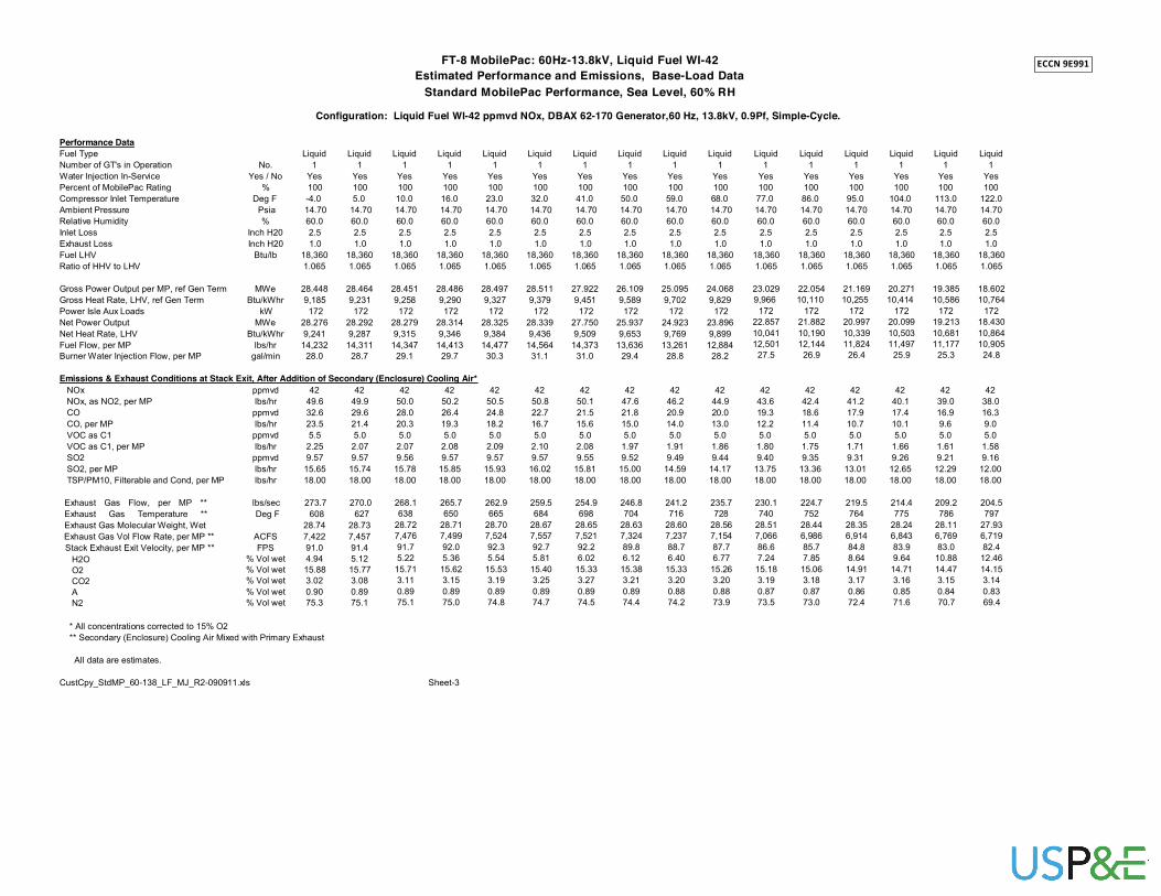
FT-8 MobilePac: 60Hz-13.8kV, Liquid Fuel WI-42 ECCN 9E991
Estimated Performance and Emissions, Base-Load Data
Standard MobilePac Performance, Sea Level, 60% RH
Configuration: Liquid Fuel WI-42 ppmvd NOx, DBAX 62-170 Generator,60 Hz, 13.8kV, 0.9Pf, Simple-Cycle. Performance Data Fuel Type Number of GT's in Operation Water Injection In-Service Percent of MobilePac Rating Compressor Inlet Temperature Ambient Pressure Relative Humidity Inlet Loss Exhaust Loss Fuel LHV Ratio of HHV to LHV Gross Power Output per MP, ref Gen Term Gross Heat Rate, LHV, ref Gen Term Power Isle Aux Loads Net Power Output Net Heat Rate, LHV Fuel Flow, per MP Burner Water Injection Flow, per MP
Liquid Liquid Liquid Liquid Liquid Liquid Liquid Liquid Liquid Liquid
No. 1 1 1 1 1 1 1 1 1 1 Yes / No Yes Yes Yes Yes Yes Yes Yes Yes Yes Yes
% 100 100 100 100 100 100 100 100 100 100 Deg F -4.0 5.0 10.0 16.0 23.0 32.0 41.0 50.0 59.0 68.0
Psia 14.70 14.70 14.70 14.70 14.70 14.70 14.70 14.70 14.70 14.70 % 60.0 60.0 60.0 60.0 60.0 60.0 60.0 60.0 60.0 60.0
Inch H20 2.5 2.5 2.5 2.5 2.5 2.5 2.5 2.5 2.5 2.5 Inch H20 1.0 1.0 1.0 1.0 1.0 1.0 1.0 1.0 1.0 1.0
Btu/lb 18,360 18,360 18,360 18,360 18,360 18,360 18,360 18,360 18,360 18,360 1.065 1.065 1.065 1.065 1.065 1.065 1.065 1.065 1.065 1.065
MWe 28.448 28.464 28.451 28.486 28.497 28.511 27.922 26.109 25.095 24.068
Btu/kWhr 9,185 9,231 9,258 9,290 9,327 9,379 9,451 9,589 9,702 9,829 kW 172 172 172 172 172 172 172 172 172 172
MWe 28.276 28.292 28.279 28.314 28.325 28.339 27.750 25.937 24.923 23.896 Btu/kWhr 9,241 9,287 9,315 9,346 9,384 9,436 9,509 9,653 9,769 9,899
lbs/hr 14,232 14,311 14,347 14,413 14,477 14,564 14,373 13,636 13,261 12,884 gal/min 28.0 28.7 29.1 29.7 30.3 31.1 31.0 29.4 28.8 28.2
Liquid Liquid Liquid Liquid
1 1 1 1 Yes Yes Yes Yes 100 100 100 100 77.0 86.0 95.0 104.0 14.70 14.70 14.70 14.70 60.0 60.0 60.0 60.0 2.5 2.5 2.5 2.5 1.0 1.0 1.0 1.0
18,360 18,360 18,360 18,360 1.065 1.065 1.065 1.065
23.029 22.054 21.169 20.271 9,966 10,110 10,255 10,414
172 172 172 172 22.857 21.882 20.997 20.099 10,041 10,190 10,339 10,503 12,501 12,144 11,824 11,497
27.5 26.9 26.4 25.9
Liquid Liquid
1 1 Yes Yes 100 100
113.0 122.0 14.70 14.70 60.0 60.0 2.5 2.5 1.0 1.0
18,360 18,360 1.065 1.065
19.385 18.602 10,586 10,764
172 172 19.213 18.430 10,681 10,864 11,177 10,905
25.3 24.8 Emissions & Exhaust Conditions at Stack Exit, After Addition of Secondary (Enclosure) Cooling Air*
NOx ppmvd 42 42 42 42 42 42 42 42 42 42 42 42 42 42 42 42 NOx, as NO2, per MP lbs/hr 49.6 49.9 50.0 50.2 50.5 50.8 50.1 47.6 46.2 44.9 43.6 42.4 41.2 40.1 39.0 38.0 CO ppmvd 32.6 29.6 28.0 26.4 24.8 22.7 21.5 21.8 20.9 20.0 19.3 18.6 17.9 17.4 16.9 16.3 CO, per MP lbs/hr 23.5 21.4 20.3 19.3 18.2 16.7 15.6 15.0 14.0 13.0 12.2 11.4 10.7 10.1 9.6 9.0 VOC as C1 ppmvd 5.5 5.0 5.0 5.0 5.0 5.0 5.0 5.0 5.0 5.0 5.0 5.0 5.0 5.0 5.0 5.0 VOC as C1, per MP lbs/hr 2.25 2.07 2.07 2.08 2.09 2.10 2.08 1.97 1.91 1.86 1.80 1.75 1.71 1.66 1.61 1.58 SO2 ppmvd 9.57 9.57 9.56 9.57 9.57 9.57 9.55 9.52 9.49 9.44 9.40 9.35 9.31 9.26 9.21 9.16 SO2, per MP lbs/hr 15.65 15.74 15.78 15.85 15.93 16.02 15.81 15.00 14.59 14.17 13.75 13.36 13.01 12.65 12.29 12.00 TSP/PM10, Filterable and Cond, per MP lbs/hr 18.00 18.00 18.00 18.00 18.00 18.00 18.00 18.00 18.00 18.00 18.00 18.00 18.00 18.00 18.00 18.00
Exhaust Gas Flow, per MP ** Exhaust Gas Temperature ** Exhaust Gas Molecular Weight, Wet Exhaust Gas Vol Flow Rate, per MP ** Stack Exhaust Exit Velocity, per MP **
H2O O2 CO2 A N2
lbs/sec 273.7 270.0 Deg F 608 627
28.74 28.73 ACFS 7,422 7,457 FPS 91.0 91.4
% Vol wet 4.94 5.12 % Vol wet 15.88 15.77 % Vol wet 3.02 3.08 % Vol wet 0.90 0.89 % Vol wet 75.3 75.1
268.1 265.7 262.9 259.5 254.9 246.8 241.2 235.7 230.1 224.7 219.5 214.4 638 650 665 684 698 704 716 728 740 752 764 775
28.72 28.71 28.70 28.67 28.65 28.63 28.60 28.56 28.51 28.44 28.35 28.24 7,476 7,499 7,524 7,557 7,521 7,324 7,237 7,154 7,066 6,986 6,914 6,843 91.7 92.0 92.3 92.7 92.2 89.8 88.7 87.7 86.6 85.7 84.8 83.9 5.22 5.36 5.54 5.81 6.02 6.12 6.40 6.77 7.24 7.85 8.64 9.64
15.71 15.62 15.53 15.40 15.33 15.38 15.33 15.26 15.18 15.06 14.91 14.71 3.11 3.15 3.19 3.25 3.27 3.21 3.20 3.20 3.19 3.18 3.17 3.16 0.89 0.89 0.89 0.89 0.89 0.89 0.88 0.88 0.87 0.87 0.86 0.85 75.1 75.0 74.8 74.7 74.5 74.4 74.2 73.9 73.5 73.0 72.4 71.6
209.2 204.5 786 797
28.11 27.93 6,769 6,719 83.0 82.4
10.88 12.46 14.47 14.15 3.15 3.14 0.84 0.83 70.7 69.4
* All concentrations corrected to 15% O2
** Secondary (Enclosure) Cooling Air Mixed with Primary Exhaust
All data are estimates. CustCpy_StdMP_60-138_LF_MJ_R2-090911.xls Sheet-3

FT-8 MobilePac: 60Hz-13.8kV, Liquid Fuel WI-42 ECCN 9E991
Estimated Performance and Emissions, Part-Load Data
Standard MobilePac Performance, Sea Level, 60% RH
Configuration: Liquid Fuel WI-42 ppmvd NOx, DBAX 62-170 Generator,60 Hz, 13.8kV, 0.9Pf, Simple-Cycle. Performance Data Fuel Type Number of GT's in Operation Water Injection In-Service Percent of MobilePac Rating Compressor Inlet Temperature Ambient Pressure Relative Humidity Inlet Loss Exhaust Loss Fuel LHV Ratio of HHV to LHV Gross Power Output per MP, ref Gen Term Gross Heat Rate, LHV, ref Gen Term Power Isle Aux Loads Net Power Output Net Heat Rate, LHV Fuel Flow, per MP Burner Water Injection Flow, per MP
Liquid Liquid Liquid Liquid
No. 1 1 1 1 Yes / No Yes Yes Yes Yes
% 100 95 85 75 Deg F 23.0 23.0 23.0 23.0 Psia 14.70 14.70 14.70 14.70 % 60.0 60.0 60.0 60.0
Inch H20 2.5 2.5 2.5 2.5 Inch H20 1.0 1.0 1.0 1.0
Btu/lb 18,360 18,360 18,360 18,360 1.065 1.065 1.065 1.065
MWe 28.497 27.072 24.222 21.373
Btu/kWhr 9,327 9,378 9,532 9,761 kW 172 172 172 172
MWe 28.325 26.900 24.050 21.201 Btu/kWhr 9,384 9,438 9,601 9,841
lbs/hr 14,477 13,828 12,576 11,363 gal/min 30.3 28.3 24.7 21.4
Liquid Liquid Liquid Liquid
1 1 1 1 Yes Yes Yes Yes 65 50 100 95
23.0 23.0 59.0 59.0 14.70 14.70 14.70 14.70 60.0 60.0 60.0 60.0 2.5 2.5 2.5 2.5 1.0 1.0 1.0 1.0
18,360 18,360 18,360 18,360 1.065 1.065 1.065 1.065
18.523 14.248 25.094 23.838 10,072 10,776 9,702 9,783
172 172 172 172 18.351 14.076 24.922 23.666 10,167 10,907 9,769 9,854 10,162 8,362 13,260 12,702
18.2 13.8 28.8 27.1
Liquid Liquid Liquid Liquid Liquid Liquid
1 1 1 1 1 1 Yes Yes Yes Yes Yes Yes 85 75 65 50 100 95
59.0 59.0 59.0 59.0 86.0 86.0 14.70 14.70 14.70 14.70 14.70 14.70 60.0 60.0 60.0 60.0 60.0 60.0 2.5 2.5 2.5 2.5 2.5 2.5 1.0 1.0 1.0 1.0 1.0 1.0
18,360 18,360 18,360 18,360 18,360 18,360 1.065 1.065 1.065 1.065 1.065 1.065
21.329 18.820 16.310 12.546 22.054 20.951 9,983 10,247 10,607 11,780 10,110 10,207
172 172 172 172 172 172 21.157 18.648 16.138 12.374 21.882 20.779 10,064 10,341 10,721 11,944 10,190 10,291 11,597 10,503 9,423 8,050 12,144 11,647
23.9 20.8 17.9 14.7 26.9 25.4
Liquid Liquid Liquid Liquid
1 1 1 1 Yes Yes Yes Yes 85 75 65 50
86.0 86.0 86.0 86.0 14.70 14.70 14.70 14.70 60.0 60.0 60.0 60.0 2.5 2.5 2.5 2.5 1.0 1.0 1.0 1.0
18,360 18,360 18,360 18,360 1.065 1.065 1.065 1.065
18.746 16.540 14.335 11.027 10,440 10,751 11,167 12,470
172 172 172 172 18.574 16.368 14.163 10.855 10,537 10,864 11,303 12,667 10,660 9,686 8,719 7,489 22.5 19.7 17.1 14.1
Emissions & Exhaust Conditions at Stack Exit, After Addition of Secondary (Enclosure) Cooling Air*
NOx ppmvd 42 42 42 42 42 NOx, as NO2, per MP lbs/hr 50.5 48.2 43.8 39.6 35.4 CO ppmvd 24.8 27.1 32.8 38.6 46.6 CO, per MP lbs/hr 18.2 18.9 20.8 22.1 23.9 VOC as C1 ppmvd 5.0 5.0 5.5 8.2 12.3 VOC as C1, per MP lbs/hr 2.09 2.00 2.01 2.70 3.62 SO2 ppmvd 9.58 9.57 9.57 9.57 9.57 SO2, per MP lbs/hr 15.92 15.21 13.83 12.50 11.18
42 42 42 42 42 42
29.1 46.2 44.3 40.4 36.6 32.8 61.9 20.9 22.7 26.5 31.7 37.4 26.1 14.0 14.6 15.5 16.8 17.8 23.7 5.0 5.0 5.0 5.1 7.7 5.71 1.91 1.83 1.67 1.56 2.08 9.58 9.48 9.49 9.49 9.50 9.51 9.20 14.59 13.97 12.76 11.55 10.37
42 42 42 42 42 42 42
28.0 42.4 40.6 37.2 33.7 30.4 26.1 43.8 18.6 20.2 23.9 27.6 33.2 38.6 17.8 11.4 11.9 12.9 13.5 14.6 14.6 10.9 5.0 5.0 5.0 5.0 5.7 8.2 2.52 1.75 1.68 1.54 1.40 1.43 1.77 9.52 9.34 9.36 9.37 9.38 9.40 9.43 8.85 13.36 12.81 11.73 10.65 9.59 8.24
Exhaust Gas Flow, per MP ** Exhaust Gas Temperature ** Exhaust Gas Molecular Weight, Wet Exhaust Gas Vol Flow Rate, per MP ** Stack Exhaust Exit Velocity, per MP **
H2O O2 CO2 A N2
lbs/sec 262.6 258.8 249.7 239.9 229.6 212.6 241.3 237.1 228.5 219.6 210.1 199.6 224.8 220.8 212.9 204.6 195.8 186.2 Deg F 664 652 629 608 586 552 716 705 685 664 642 617 752 741 721 701 680 654
28.70 28.71 28.73 28.75 28.77 28.81 28.60 28.61 28.64 28.66 28.68 28.70 28.44 28.45 28.47 28.49 28.51 28.54 ACFS 7,508 7,317 6,910 6,504 6,093 5,451 7,241 7,047 6,666 6,283 5,894 5,465 6,991 6,805 6,445 6,082 5,713 5,305 FPS 92.1 89.7 84.7 79.8 74.7 66.8 88.8 86.4 81.8 77.0 72.3 67.0 85.7 83.4 79.0 74.6 70.1 65.1
% Vol wet 5.54 5.33 4.95 4.59 4.23 3.67 6.40 6.22 5.86 5.50 5.14 4.66 7.85 7.68 7.34 7.00 6.65 6.18 % Vol wet 15.53 15.70 16.01 16.31 16.62 17.12 15.33 15.48 15.77 16.07 16.38 16.83 15.06 15.20 15.49 15.77 16.07 16.51 % Vol wet 3.19 3.10 2.93 2.76 2.58 2.30 3.20 3.12 2.96 2.80 2.62 2.36 3.18 3.10 2.94 2.78 2.62 2.37 % Vol wet 0.89 0.89 0.89 0.90 0.90 0.90 0.88 0.88 0.89 0.89 0.89 0.90 0.87 0.87 0.87 0.88 0.88 0.88 % Vol wet 74.8 75.0 75.2 75.4 75.7 76.0 74.2 74.3 74.5 74.7 75.0 75.2 73.0 73.1 73.4 73.6 73.8 74.1
* All concentrations corrected to 15% O2
** Secondary (Enclosure) Cooling Air Mixed with Primary Exhaust
All data are estimates. CustCpy_StdMP_60-138_LF_MJ_R2-090911.xls Sheet-4

FT-8 MobilePac: 60Hz-13.8kV, Liquid Fuel - DRY ECCN 9E991
Estimated Performance and Emissions, Base-Load Data
Standard MobilePac Performance, Sea Level, 60% RH
Configuration: Liquid Fuel- Std. Combustor-DRY, DBAX 62-170 Generator,60 Hz, 13.8kV, 0.9Pf, Simple-Cycle. Performance Data Fuel Type Number of GT's in Operation Water Injection In-Service Percent of MobilePac Rating Compressor Inlet Temperature Ambient Pressure Relative Humidity Inlet Loss Exhaust Loss Fuel LHV Ratio of HHV to LHV Gross Power Output per MP, ref Gen Term Gross Heat Rate, LHV, ref Gen Term Power Isle Aux Load Net Power Output Net Heat Rate, LHV Fuel Flow, per MP Burner Water Injection Flow, per MP
Liquid Liquid Liquid Liquid Liquid Liquid Liquid Liquid Liquid Liquid Liquid
No. 1 1 1 1 1 1 1 1 1 1 1 Yes / No No No No No No No No No No No No
% 100 100 100 100 100 100 100 100 100 100 100 Deg F -4.0 5.0 10.0 16.0 23.0 32.0 41.0 50.0 59.0 68.0 77.0 Psia 14.70 14.70 14.70 14.70 14.70 14.70 14.70 14.70 14.70 14.70 14.70 % 60.0 60.0 60.0 60.0 60.0 60.0 60.0 60.0 60.0 60.0 60.0
Inch H20 2.5 2.5 2.5 2.5 2.5 2.5 2.5 2.5 2.5 2.5 2.5 Inch H20 1.0 1.0 1.0 1.0 1.0 1.0 1.0 1.0 1.0 1.0 1.0
Btu/lb 18,360 18,360 18,360 18,360 18,360 18,360 18,360 18,360 18,360 18,360 18,360 1.065 1.065 1.065 1.065 1.065 1.065 1.065 1.065 1.065 1.065 1.065
MWe 28.160 28.171 28.176 28.134 27.284 25.868 24.063 22.590 21.433 20.391 19.421
Btu/kWhr 8,814 8,852 8,875 8,903 8,966 9,080 9,235 9,392 9,539 9,688 9,841 kW 114 114 114 114 114 114 114 114 114 114 114
MWe 28.046 28.057 28.062 28.020 27.170 25.754 23.949 22.476 21.319 20.277 19.307 Btu/kWhr 8,850 8,888 8,911 8,939 9,004 9,120 9,279 9,440 9,590 9,742 9,899
lbs/hr 13,518 13,583 13,619 13,643 13,324 12,793 12,104 11,556 11,136 10,759 10,410 gal/min 0.0 0.0 0.0 0.0 0.0 0.0 0.0 0.0 0.0 0.0 0.0
Liquid Liquid Liquid
1 1 1 No No No 100 100 100 86.0 95.0 104.0 14.70 14.70 14.70 60.0 60.0 60.0 2.5 2.5 2.5 1.0 1.0 1.0
18,360 18,360 18,360 1.065 1.065 1.065
18.509 17.662 16.866 10,003 10,174 10,352
114 114 114 18.395 17.548 16.752 10,065 10,240 10,423 10,084 9,787 9,510
0.0 0.0 0.0
Liquid Liquid
1 1 No No 100 100
113.0 122.0 14.70 14.70 60.0 60.0 2.5 2.5 1.0 1.0
18,360 18,360 1.065 1.065
16.077 15.390 10,547 10,742
114 114 15.963 15.276 10,622 10,822 9,236 9,004
0.0 0.0 Emissions & Exhaust Conditions at Stack Exit, After Addition of Secondary (Enclosure) Cooling Air*
NOx ppmvd 337 360 373 390 396 399 396 398 407 416 425 435 446 456 466 476 NOx, as NO2, per MP lbs/hr 378.5 406.3 421.7 441.7 438.5 424.3 397.8 382.0 376.2 371.9 367.5 364.2 362.3 360.6 357.5 356.1 CO ppmvd 27.9 25.4 24.1 22.6 22.0 21.8 22.1 21.9 21.2 20.4 19.7 18.9 18.3 17.6 17.0 16.4 CO, per MP lbs/hr 19.0 17.5 16.6 15.6 14.9 14.1 13.5 12.8 11.9 11.1 10.4 9.7 9.0 8.5 8.0 7.5 VOC as C1 ppmvd 5.0 5.0 5.0 5.0 5.0 5.0 5.0 5.0 5.0 5.0 5.0 5.0 5.0 5.0 5.0 5.0 VOC as C1, per MP lbs/hr 1.95 1.96 1.97 1.97 1.92 1.85 1.75 1.67 1.61 1.55 1.50 1.46 1.41 1.37 1.33 1.30 SO2 ppmvd 9.62 9.62 9.62 9.62 9.62 9.60 9.57 9.53 9.48 9.45 9.40 9.36 9.31 9.26 9.21 9.16 SO2, per MP lbs/hr 14.87 14.94 14.98 15.01 14.66 14.07 13.31 12.71 12.25 11.83 11.45 11.09 10.77 10.46 10.16 9.90 TSP/PM10, Filterable and Cond, per MP lbs/hr 18.00 18.00 18.00 18.00 18.00 18.00 18.00 18.00 18.00 18.00 18.00 18.00 18.00 18.00 18.00 18.00
Exhaust Gas Flow, per MP ** Exhaust Gas Temperature ** Exhaust Gas Molecular Weight, Wet Exhaust Gas Vol Flow Rate, per MP ** Stack Exhaust Exit Velocity, per MP **
H2O O2 CO2 A N2
lbs/sec 268.5 264.6 262.5 260.0 255.1 247.9 239.6 232.4 226.2 220.4 214.9 209.6 204.6 199.7 194.8 190.2 Deg F 628 648 660 673 682 691 696 705 716 728 739 751 763 775 786 798
28.99 28.99 28.99 28.98 28.98 28.96 28.94 28.92 28.89 28.85 28.80 28.73 28.64 28.53 28.39 28.21 ACFS 7,351 7,384 7,403 7,422 7,338 7,190 6,987 6,832 6,721 6,621 6,530 6,446 6,376 6,309 6,242 6,191 FPS 90.1 90.5 90.8 91.0 90.0 88.2 85.7 83.8 82.4 81.2 80.1 79.1 78.2 77.4 76.5 75.9
% Vol wet 2.61 2.69 2.75 2.82 2.88 2.97 3.08 3.25 3.52 3.87 4.34 4.96 5.76 6.78 8.06 9.66 % Vol wet 16.5 16.4 16.3 16.3 16.3 16.3 16.4 16.4 16.3 16.3 16.2 16.1 15.9 15.7 15.5 15.2 % Vol wet 2.94 2.99 3.02 3.05 3.04 3.01 2.96 2.92 2.90 2.88 2.87 2.86 2.85 2.84 2.82 2.82 % Vol wet 0.92 0.92 0.92 0.91 0.91 0.91 0.91 0.91 0.91 0.90 0.90 0.89 0.89 0.88 0.87 0.85 % Vol wet 77.0 77.0 76.9 76.9 76.9 76.8 76.7 76.5 76.3 76.0 75.6 75.2 74.5 73.7 72.7 71.5
* All concentrations corrected to 15% O2
** Secondary (Enclosure) Cooling Air Mixed with Primary Exhaust
All data are estimates. CustCpy_StdMP_60-138_LF_MJ_R2-090911.xls Sheet-5

FT-8 MobilePac: 60Hz-13.8kV, Liquid Fuel - DRY ECCN 9E991
Estimated Performance and Emissions, Part-Load Data
Standard MobilePac Performance, Sea Level, 60% RH
Configuration: Liquid Fuel- Std. Combustor-DRY, DBAX 62-170 Generator,60 Hz, 13.8kV, 0.9Pf, Simple-Cycle. Performance Data Fuel Type Number of GT's in Operation Water Injection In-Service Percent of MobilePac Rating Compressor Inlet Temperature Ambient Pressure Relative Humidity Inlet Loss Exhaust Loss Fuel LHV Ratio of HHV to LHV Gross Power Output per MP, ref Gen Term Gross Heat Rate, LHV, ref Gen Term Power Isle Aux Load Net Power Output Net Heat Rate, LHV Fuel Flow, per MP Burner Water Injection Flow, per MP
Liquid Liquid Liquid Liquid Liquid
No. 1 1 1 1 1 Yes / No No No No No No
% 100 95 85 75 65 Deg F 23.0 23.0 23.0 23.0 23.0 Psia 14.70 14.70 14.70 14.70 14.70 % 60.0 60.0 60.0 60.0 60.0
Inch H20 2.5 2.5 2.5 2.5 2.5 Inch H20 1.0 1.0 1.0 1.0 1.0
Btu/lb 18,360 18,360 18,360 18,360 18,360 1.065 1.065 1.065 1.065 1.065
MWe 27.284 25.920 23.192 20.463 17.735
Btu/kWhr 8,966 9,031 9,207 9,448 9,772 kW 114 114 114 114 114
MWe 27.170 25.806 23.078 20.349 17.621 Btu/kWhr 9,004 9,071 9,252 9,501 9,836
lbs/hr 13,324 12,750 11,629 10,531 9,440 gal/min 0.0 0.0 0.0 0.0 0.0
Liquid Liquid Liquid Liquid
1 1 1 1 No No No No 50 100 95 85
23.0 59.0 59.0 59.0 14.70 14.70 14.70 14.70 60.0 60.0 60.0 60.0 2.5 2.5 2.5 2.5 1.0 1.0 1.0 1.0
18,360 18,360 18,360 18,360 1.065 1.065 1.065 1.065
13.642 21.433 20.361 18.218 10,507 9,539 9,640 9,881
114 114 114 114 13.528 21.319 20.247 18.104 10,595 9,590 9,694 9,944 7,807 11,136 10,691 9,805
0.0 0.0 0.0 0.0
Liquid Liquid Liquid Liquid Liquid
1 1 1 1 1 No No No No No 75 65 50 100 95
59.0 59.0 59.0 86.0 86.0 14.70 14.70 14.70 14.70 14.70 60.0 60.0 60.0 60.0 60.0 2.5 2.5 2.5 2.5 2.5 1.0 1.0 1.0 1.0 1.0
18,360 18,360 18,360 18,360 18,360 1.065 1.065 1.065 1.065 1.065
16.075 13.932 10.717 18.509 17.584 10,201 10,619 11,883 10,003 10,125
114 114 114 114 114 15.961 13.818 10.603 18.395 17.470 10,274 10,707 12,011 10,065 10,192 8,932 8,058 6,936 10,084 9,697
0.0 0.0 0.0 0.0 0.0
Liquid Liquid Liquid Liquid
1 1 1 1 No No No No 85 75 65 50
86.0 86.0 86.0 86.0 14.70 14.70 14.70 14.70 60.0 60.0 60.0 60.0 2.5 2.5 2.5 2.5 1.0 1.0 1.0 1.0
18,360 18,360 18,360 18,360 1.065 1.065 1.065 1.065
15.733 13.882 12.031 9.255 10,415 10,787 11,620 12,683
114 114 114 114 15.619 13.768 11.917 9.141 10,491 10,877 11,732 12,841 8,924 8,156 7,615 6,393
0.0 0.0 0.0 0.0 Emissions & Exhaust Conditions at Stack Exit, After Addition of Secondary (Enclosure) Cooling Air*
NOx ppmvd 396 370 328 289 255 NOx, as NO2, per MP lbs/hr 438.5 391.9 316.5 252.1 199.2 CO ppmvd 22.0 24.4 29.2 35.5 42.9 CO, per MP lbs/hr 14.9 15.7 17.2 18.8 20.4 VOC as C1 ppmvd 5.0 5.0 5.0 6.7 10.4 VOC as C1, per MP lbs/hr 1.92 1.84 1.68 2.03 2.83 SO2 ppmvd 9.62 9.61 9.61 9.61 9.61 SO2, per MP lbs/hr 14.66 14.03 12.79 11.58 10.38
208 407 384 345 307 274 246
134.2 376.2 340.6 280.3 227.5 182.9 141.2 58.0 21.2 23.1 27.1 32.4 38.3 45.3 22.8 11.9 12.5 13.4 14.6 15.6 15.8 20.5 5.0 5.0 5.0 5.4 8.1 11.7 4.62 1.61 1.54 1.41 1.39 1.88 2.33 9.61 9.48 9.49 9.49 9.50 9.51 9.52 8.59 12.25 11.76 10.79 9.82 8.86 7.63
435 413 370 333 327 267
364.2 332.4 274.2 225.2 206.1 141.5 18.9 20.7 24.4 28.5 29.5 39.6 9.7 10.1 11.0 11.7 11.3 12.8 5.0 5.0 5.0 5.0 5.0 8.7
1.46 1.40 1.29 1.18 1.10 1.61 9.36 9.37 9.38 9.40 9.41 9.44 11.09 10.67 9.82 8.97 8.38 7.03
Exhaust Gas Flow, per MP ** Exhaust Gas Temperature ** Exhaust Gas Molecular Weight, Wet Exhaust Gas Vol Flow Rate, per MP ** Stack Exhaust Exit Velocity, per MP **
H2O O2 CO2 A N2
lbs/sec 255.1 251.2 242.7 233.6 224.0 208.1 226.2 222.6 215.2 207.3 198.9 189.8 209.6 206.3 199.4 192.2 189.1 176.3 Deg F 682 669 644 621 597 560 716 705 684 663 641 614 751 741 720 700 688 651
28.98 28.97 28.97 28.97 28.97 28.96 28.89 28.89 28.89 28.88 28.88 28.88 28.73 28.73 28.72 28.72 28.72 28.72 ACFS 7,338 7,144 6,753 6,362 5,966 5,348 6,721 6,554 6,218 5,880 5,534 5,152 6,446 6,292 5,979 5,662 5,517 4,976 FPS 90.0 87.6 82.8 78.0 73.2 65.6 82.4 80.4 76.3 72.1 67.9 63.2 79.1 77.2 73.3 69.4 67.7 61.0
% Vol wet 2.88 2.80 2.66 2.52 2.37 2.14 3.52 3.45 3.33 3.20 3.07 2.87 4.96 4.90 4.79 4.67 4.55 4.35 % Vol wet 16.3 16.4 16.7 16.9 17.2 17.6 16.3 16.4 16.7 16.9 17.1 17.5 16.1 16.2 16.4 16.6 16.8 17.2 % Vol wet 3.04 2.96 2.80 2.63 2.47 2.20 2.90 2.83 2.69 2.54 2.39 2.16 2.86 2.79 2.65 2.52 2.38 2.15 % Vol wet 0.91 0.91 0.92 0.92 0.92 0.92 0.91 0.91 0.91 0.91 0.91 0.91 0.89 0.89 0.90 0.90 0.90 0.90 % Vol wet 76.9 76.9 76.9 77.0 77.1 77.2 76.3 76.3 76.4 76.4 76.5 76.6 75.2 75.2 75.2 75.3 75.3 75.4
* All concentrations corrected to 15% O2
** Secondary (Enclosure) Cooling Air Mixed with Primary Exhaust
All data are estimates. CustCpy_StdMP_60-138_LF_MJ_R2-090911.xls Sheet-6

Pratt and Whitney Plot_Gr
Est.
Gro
ss P
ower
Out
put p
er M
P, re
f Gen
Ter
m (M
W)


Pratt and Whitney Plot_Gross Heat Rate E. Standard Performances- CustCpy_StdMP_60-138_LF_MJ_R2-090911.xls
Figure 11006, 09/09/2011 Standard MobilePac Performance
Estimated "Base Load" Gross Heat Rate (LHV) vs Compressor Inlet Temperature FT8 MobilePac, 60Hz-13.8kV-0.9Pf, Liquid Fuel-WI42 & DRY
Sea Level, 60% RH, 2.5 in W.C. Inlet Loss, 1.0 in Exhaust Loss 10,900
ECCN 9E991
Liquid Fuel LHV = 18,360 Btu/lb
10,700
Gross Heat Rate_LF-WI42 Gross Heat Rate_LF-DRY
10,500
10,300
10,100
9,900
9,700
9,500
9,300
9,100
8,900
8,700
-10 0 10 20 30 40 50 60 70 80 90 100 110 120 130
Compressor Inlet Temperature , deg F
Est.
Gro
ss H
eat R
ate,
LH
V, r
ef G
en T
erm
(Btu
/kW
hr)

![E] E] XP SP2TWireIess Zero E] XP SPI El r Wireless Zero ......E] E] XP SP2TWireIess Zero E] XP SPI El" r Wireless Zero 'Windows XP SP(Service Pack) l) 2) DATA DVD RW WNG54R3102 Autorunexe](https://img.pdfslide.us/doc/110x75/603a61e1291a430d3b36bdf4/e-e-xp-sp2twireiess-zero-e-xp-spi-el-r-wireless-zero-e-e-xp-sp2twireiess.jpg)


![[Induction] sessão 4 @xp e gle](https://img.pdfslide.us/doc/110x75/549528f9b4795971338b47ac/induction-sessao-4-xp-e-gle.jpg)