Embed Size (px)
Citation preview

Output SEAP August 2013 / 10
As the air is added to the flotation cell, bubbles rise through the slurry, up through the froth to the exposed froth surface, hopefully with product attached. Here it expands and eventually overflows the launder lip.
As mentioned, transportation of mineral particles from bulk slurry to the launder lip is one of the froth’s primary functions. It therefore logically follows that without a stable froth, there will be poor product
Most flotation cells comprise of a pulp and froth phase. The froth phase is used primarily for three functions: 1. to create an environment for floated particles to separate from the bulk slurry; 2. to allow selective concentration of the desirable particles over non-desirable particles; 3. transportation of mineral particles from bulk slurry to the launder lip.
FROTHING AT THE LIP - STABILITY IN YOUR FLOTATION CELL Author: Jason Heath
Large froth surface area (low degree of crowding) in an Outotec TC50 Flotation Cell at a recently commissioned flotation concentrator in Australia.
transportation to the launder lip, and hence poor recovery and overall performance of the flotation cell.
THE CONCEPT OF THE FROTH CARRY RATE
Froth in a flotation cell is a combination of water, air and solid particles. The froth itself is quite unstable and you will often see bubbles breaking and coalescing into larger bubbles. Given this inherent
Output SEAP August 2013 / 11
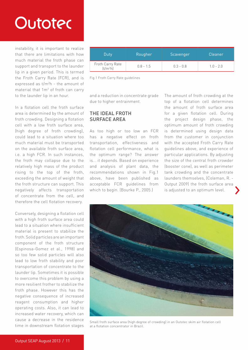
Small froth surface area (high degree of crowding) in an Outotec skim air flotation cell at a flotation concentrator in Brazil.
instability, it is important to realize that there are limitations with how much material the froth phase can support and transport to the launder lip in a given period. This is termed the Froth Carry Rate (FCR), and is expressed as t/m2h - the amount of material that 1m2 of froth can carry to the launder lip in an hour.
In a flotation cell the froth surface area is determined by the amount of froth crowding. Designing a flotation cell with a low froth surface area, (high degree of froth crowding), could lead to a situation where too much material must be transported on the available froth surface area, i.e. a high FCR. In such instances, the froth may collapse due to the relatively high mass of the product rising to the top of the froth, exceeding the amount of weight that the froth structure can support. This negatively affects transportation of concentrate from the cell, and therefore the cell flotation recovery.
Conversely, designing a flotation cell with a high froth surface area could lead to a situation where insufficient material is present to stabilize the froth. Solid particles are an important component of the froth structure (Espinosa-Gomez et al., 1998) and so too few solid particles will also lead to low froth stability and poor transportation of concentrate to the launder lip. Sometimes it is possible to overcome this problem by using a more resilient frother to stabilize the froth phase. However this has the negative consequence of increased reagent consumption and higher operating costs. Also, it can lead to increased water recovery, which can cause a decrease in the residence time in downstream flotation stages
and a reduction in concentrate grade due to higher entrainment.
THE IDEAL FROTH SURFACE AREA
As too high or too low an FCR has a negative effect on froth transportation, effectiveness and flotation cell performance, what is the optimum range? The answer is... it depends. Based on experience and analysis of plant data, the recommendations shown in Fig.1 above, have been published as acceptable FCR guidelines from which to begin. (Bourke P., 2005.)
Fig.1 Froth Carry Rate guidelines
Duty Rougher Scavenger Cleaner
Froth Carry Rate (t/m2h) 0.8 - 1.5 0.3 - 0.8 1.0 - 2.0
The amount of froth crowding at the top of a flotation cell determines the amount of froth surface area for a given flotation cell. During the project design phase, the optimum amount of froth crowding is determined using design data from the customer in conjunction with the accepted Froth Carry Rate guidelines above, and experience of particular applications. By adjusting the size of the central froth crowder (booster cone), as well as perimeter tank crowding and the concentrate launders themselves, (Coleman, R. - Output 2009) the froth surface area is adjusted to an optimum level.

Output SEAP August 2013 / 12
PROBLEMS WITH FROTH CROWDING
When there is too much or too little froth crowding, this will lead to the FCR being outside the optimum design range. Problems with the level of froth crowding normally arise from one of the following reasons, or a combination thereof:
� Insufficient detail in the design phase: flotation cell design, including the level of froth crowding, is determined based on the process data received during the plant design phase. If this data is scarce or not of sufficiently high accuracy this can lead to an incorrect froth crowding design. It is therefore important to provide your supplier with the best quality process data possible to allow the flotation cells to be properly designed for each duty. As an example, flotation circuit design often calls for increasing flotation cell crowding down a bank of cells to optimize the FCR at each flotation cell. However this also requires the largest amount of process data (e.g. kinetic flotation data) at the design phase, which is not always available.
� “Safety factors”: during pre-feasibility and bankable feasibility studies, it is commonplace for engineers to add in safety factors to provide safety against underestimating the size of the required equipment. In the context of flotation, overestimating can also be detrimental. If the froth
surface area is overestimated then the FCR can be lower than the optimum range, which can lead to froth instability and/or higher operating costs.
� Feed grade: during the initial stages of a project, the ore produced should ideally be close to the plant design feed grade. As the project advances however, the feed grade delivered to the processing plant will often differ from the design feed grade. This may be due to numerous factors, such as a forecast decline in grade, changes in mining practices and schedule, changes in commodity prices, and so on. A change in feed grade will affect the amount of concentrate to be transported by the froth to the concentrate launder, (for a given concentrate grade), and subsequently alter the FCR. In extreme examples of feed grade variation, some operating grades can be half the design grade. This means that the installed froth crowding is insufficient by approximately a factor of two.
About the author...Jason Heath is currently Technology Leader – Flotation for Outotec in the South East Asia region. Jason’s 10 year career has seen him gain metallurgical project and operational experience in several areas, predominately in gold hydrometallurgy and processing, and base metal flotation. His current personal interests are new flotation equipment design, and surface chemistry and the flotation process. Jason holds a BSc Hons (1st class), Chemistry, Metallurgy from Curtin University of Technology.
If you would like more information, click here to [email protected]
A knowledgeable supplier can implement strategies to rectify this type of problem using equipment modernizations and upgrades, bringing the cells back under control.
IN SUMMARY
Froth transport and properties are a very important component of overall flotation cell performance. Hence, accurate design of froth crowding is also a significant contributor to overall flotation cell performance. Therefore, to ensure the optimum froth crowding design for a given application, the available design data must be carefully reviewed for the cell design stage of your project.
References:Bourke, P., Output 2005. Coleman, R., Output 2009 Espinosa-Gomez, R, Finch, J A, Yianatos and Doby G S, 1998. Technical note: Flotation column carrying capacity: particle size and density effects. Mineral Engineering Vol 1, No. 1, pp 77-79.