Embed Size (px)
Citation preview
Frost Protection of Pipe SystemsApplication Sheet
Frost Protection
Intelligent heating
Table of ContentsApplication briefing ..................................................................................................................... 3Product Selection .......................................................................................................................... 4Calculation ....................................................................................................................................... 5Installation summary ................................................................................................................... 6Commissioning .............................................................................................................................. 7Important ......................................................................................................................................... 7Performance .................................................................................................................................... 8
List of Application Sheets
Indoor Heating, New buildingFloor Heating in Concrete Floor ConstructionsFloor Heating in Joist Floor Constructions
Indoor Heating, RenovationFloor Heating under Fixed Dry FlooringsEmbedded Floor Heating under All FlooringsFloor Heating under Removable Floorings
Frost ProtectionFrost Protection of Pipe SystemsFrost Protection of Roof and Gutter SystemsMelting Snow and Ice from Ground AreasFrost Protection of Floor ConstructionsFrost Protection of Concrete Hardening Process
Temperature MaintenanceTemperature Maintenance of Pipe SystemsCondensation Protection of Floors and Surfaces
Heating within AgricultureHeating Stable FloorsHeating Seed BedsHeating Vine Yards
3
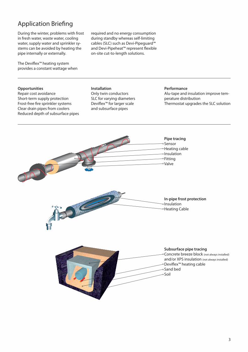
Application BriefingDuring the winter, problems with frost in fresh water, waste water, cooling water, supply water and sprinkler sy-stems can be avoided by heating the pipe internally or externally.
The Deviflex™ heating system provides a constant wattage when
OpportunitiesRepair cost avoidanceShort-term supply protection Frost-free fire sprinkler systems Clear drain pipes from coolersReduced depth of subsurface pipes
Installation Only twin conductorsSLC for varying diametersDeviflex™ for larger scale and subsurface pipes
PerformanceAlu-tape and insulation improve tem-perature distributionThermostat upgrades the SLC solution
required and no energy consumption during standby whereas self-limiting cables (SLC) such as Devi-Pipeguard™ and Devi-Pipeheat™ represent flexible on-site cut-to-length solutions.
Pipe tracingSensorHeating cableInsulationFittingValve
In-pipe frost protectionInsulation Heating Cable
Subsurface pipe tracingConcrete breeze block (not always installed)
and/or XPS insulation (not always installed)
Deviflex™ heating cableSand bedSoil
4
Product Selection
Product Options Description
Deviflex™DIN IEC 60800 Constant wattage
DTIP-6, DTIP-10DTIV-9
Twin conductorIn-pipe cable, 10 bar, VA approved
DIN VDE 0254Self-limiting cable
Devi-Pipeguard™ 10 / 15 / 25Devi-Pipeheat™ 10
Self-limiting cable, PVC freeIn-pipe cable, 10 bar, VA approved
Thermostat Devireg 330 Devireg 610
-10 to +10°C, IP20, 16 A, DIN rail-10 to +50°C, IP44, 10 A
Sensor NTC sensor cable for Devireg 330, 610 3 m, 6 m and 10 m, 15k Ω
Accessories
For self-limiting cables
Compression gland ¾” - 1” male threadDevireg 610 kitAluminium tape 38 mm x 50 mConnection boxConnection box kitAngle brace for connection boxEnd terminationConnectors
for in-pipe heatingfor pipe mountingfor attaching cables to plastic pipes
Other Insulation (e.g. styrofoam)RCD according to local legislation Warning StickerFabric tape
XPS with high compressive strengthResidual-current device
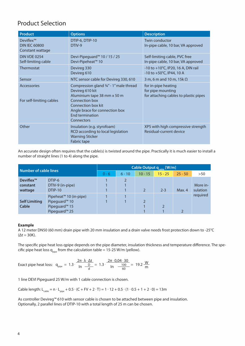
An accurate design often requires that the cable(s) is twisted around the pipe. Practically it is much easier to install a number of straight lines (1 to 4) along the pipe.
Number of cable lines Cable Output qcable [W/m]
0 - 6 6 - 10 10 - 15 15 - 25 25 - 50 >50
Deviflex™ constant wattage
DTIP-6DTIV-9 (in-pipe)DTIP-10
111
211 2 2-3 Max. 4
More in-sulation required
Self LimitingCable
Pipeheat™ 10 (in-pipe)Pipeguard™ 10Pipeguard™ 15Pipeguard™ 25
11
11 2
11
21 2
ExampleA 12 meter DN50 (60 mm) drain pipe with 20 mm insulation and a drain valve needs frost protection down to -25°C (Δt = 30K).
The specific pipe heat loss qpipe depends on the pipe diameter, insulation thickness and temperature difference. The spe-cific pipe heat loss q
pipe from the calculation table = 15-25 W/m (yellow).
Exact pipe heat loss:
1 line DEVI Pipeguard 25 W/m with 1 cable connection is chosen.
Cable length: Lcable
= n · Lpipe
+ 0.5 · (C + FV + 2 · T) = 1 · 12 + 0.5 · (1 · 0.5 + 1 + 2 · 0) = 13m
As controller Devireg™ 610 with sensor cable is chosen to be attached between pipe and insulation.Optionally, 2 parallel lines of DTIP-10 with a total length of 25 m can be chosen.
qpipe
= 1.3 .2π . λ . Δt
= 1.3 .2π . 0,04 . 30
= 19.2 WIn D In 100
md 60
5
CC = π . d . √ 1n2 - 1
qpipe
= 1.3 .2π . λ . ΔtIn D
d
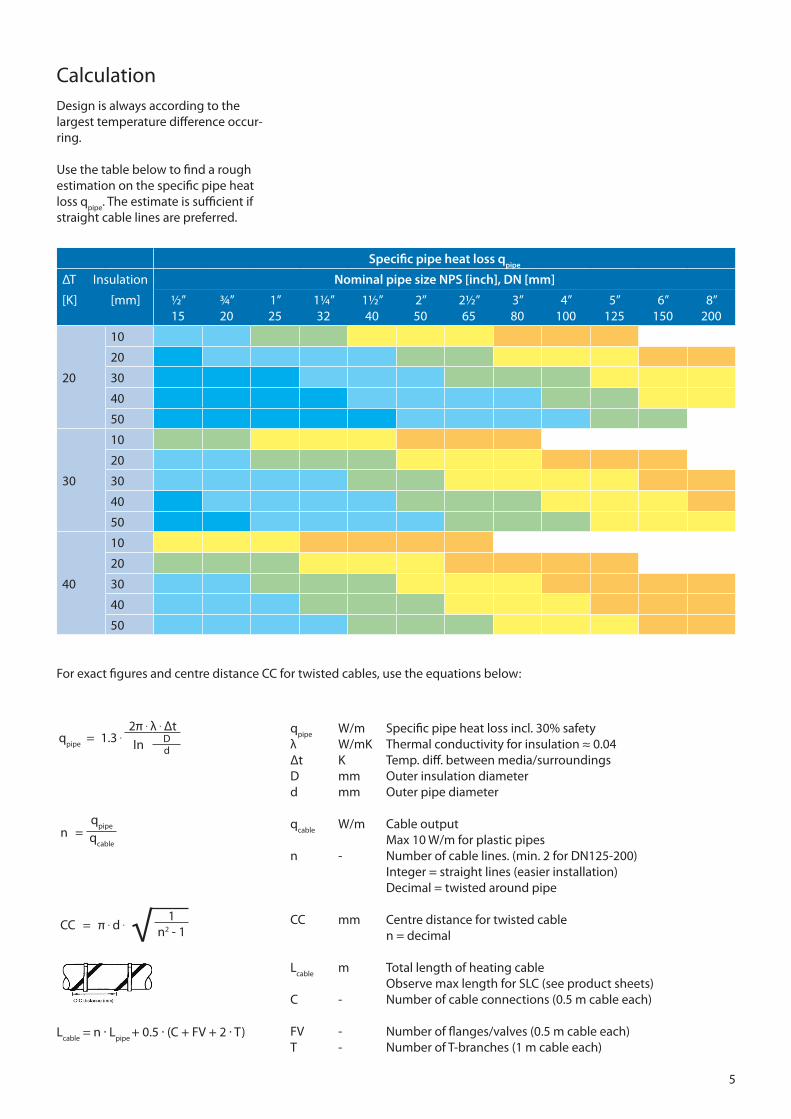
Calculation Design is always according to the largest temperature difference occur-ring.
Use the table below to find a rough estimation on the specific pipe heat loss q
pipe. The estimate is sufficient if
straight cable lines are preferred.
Specific pipe heat loss qpipe
ΔT Insulation Nominal pipe size NPS [inch], DN [mm]
[K] [mm] ½”15
¾”20
1”25
1¼”32
1½”40
2”50
2½”65
3”80
4”100
5”125
6”150
8”200
20
10
20
30
40
50
30
10
20
30
40
50
40
10
20
30
40
50
For exact figures and centre distance CC for twisted cables, use the equations below:
qpipe
W/m Specific pipe heat loss incl. 30% safetyλ W/mK Thermal conductivity for insulation ≈ 0.04 Δt K Temp. diff. between media/surroundingsD mm Outer insulation diameterd mm Outer pipe diameter
qcable
W/m Cable output Max 10 W/m for plastic pipesn - Number of cable lines. (min. 2 for DN125-200) Integer = straight lines (easier installation) Decimal = twisted around pipe
CC mm Centre distance for twisted cable n = decimal
Lcable
m Total length of heating cable Observe max length for SLC (see product sheets)C - Number of cable connections (0.5 m cable each)
FV - Number of flanges/valves (0.5 m cable each)T - Number of T-branches (1 m cable each)
Lcable
= n · Lpipe
+ 0.5 · (C + FV + 2 · T)
n =q
pipe
qcable
6
Installation Summary
20mm –25o C
DN25+5
o C
12
6
9 3
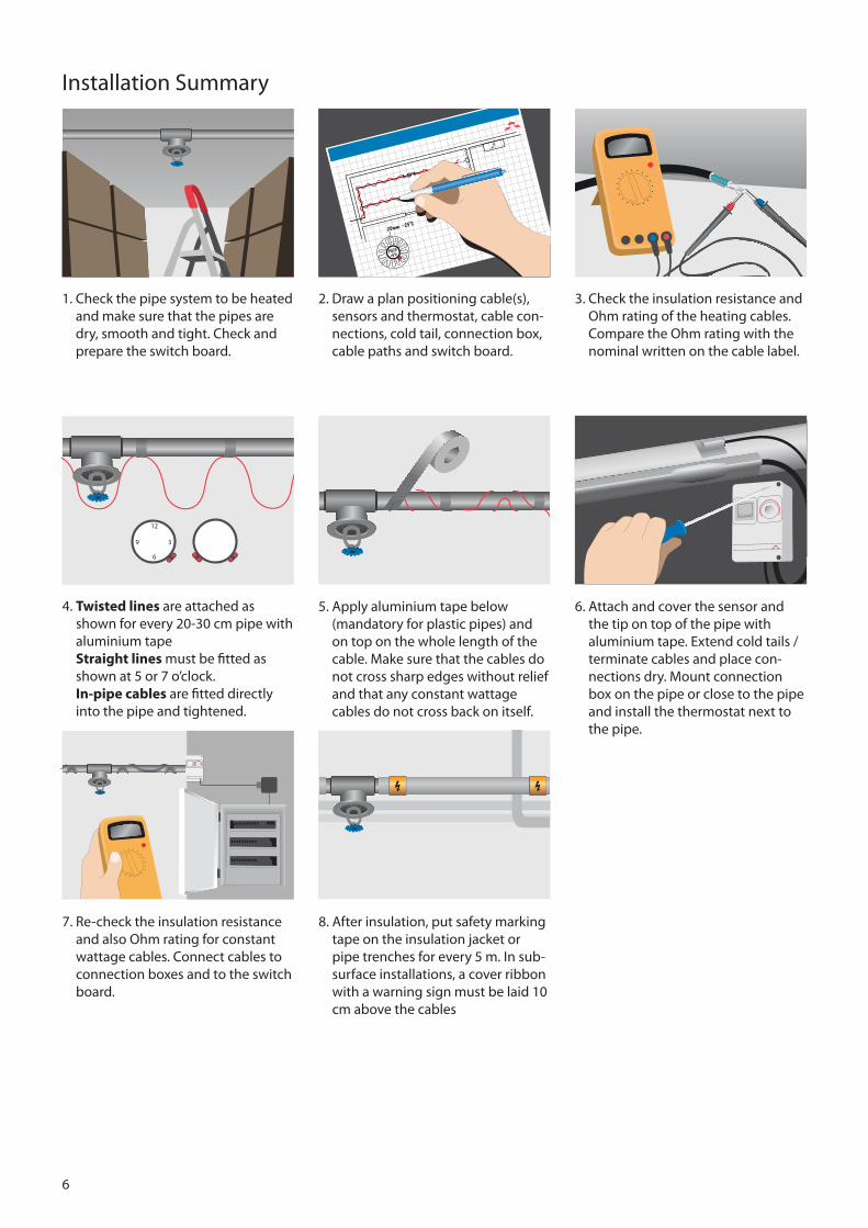
2. Draw a plan positioning cable(s), sensors and thermostat, cable con-nections, cold tail, connection box, cable paths and switch board.
1. Check the pipe system to be heated and make sure that the pipes are dry, smooth and tight. Check and prepare the switch board.
5. Apply aluminium tape below (mandatory for plastic pipes) and on top on the whole length of the cable. Make sure that the cables do not cross sharp edges without relief and that any constant wattage cables do not cross back on itself.
8. After insulation, put safety marking tape on the insulation jacket or pipe trenches for every 5 m. In sub-surface installations, a cover ribbon with a warning sign must be laid 10 cm above the cables
3. Check the insulation resistance and Ohm rating of the heating cables. Compare the Ohm rating with the nominal written on the cable label.
6. Attach and cover the sensor and the tip on top of the pipe with aluminium tape. Extend cold tails / terminate cables and place con-nections dry. Mount connection box on the pipe or close to the pipe and install the thermostat next to the pipe.
4. Twisted lines are attached as shown for every 20-30 cm pipe with aluminium tape Straight lines must be fitted as shown at 5 or 7 o’clock. In-pipe cables are fitted directly into the pipe and tightened.
7. Re-check the insulation resistance and also Ohm rating for constant wattage cables. Connect cables to connection boxes and to the switch board.
7
Commissioning
Important
9) Re-check and compare the insula-tion resistance and also Ohm rating for constant wattage cables and earth resistance
10) The Devireg™ thermostat must be commissioned as prescribed in the thermostat manual. Recommen-ded pipe temperature setting is +3 to +6°C
11) Train the end user or daily super-visor in the operation and main-tenance of the frost protection system
12) Before every season, check for faults in the switchboard, thermo-stat and sensors. Re-check and compare the insulation resistance and also Ohm rating for constant wattage cables and earth resi-stance
Do not install cables in temperature below -5°C.
Do not cut the Deviflex™ cable!
Do not interconnect the two conduc-tors in a self-limiting cable.
Do not connect self-limiting cables and constant wattage cables in series!
Observe that Deviflex™ cables are used in subsurface installations ex-pect in the case of pipes with built-in metal tracer pipe.
Observe maximum length for self-limiting cables (see Product Sheet).
Self-limiting cables must be stored in a dry place after shearing.
Do not use PVC insulation tape to at-tach self-limiting cables as it contains plasticizers.
Check the cable Ohm rating (De-viflex™ constant wattage only) / insulation resistance (both Deviflex™ and self-limiting cables) before and after installation.
All electrical connections must be done by authorized persons accor-ding to local regulations.
8
DEVI A/S Ulvehavevej 61DK-7100 Vejle Tel: +45 7642 4700Fax: +45 7642 4701 www.devi.com
Performance
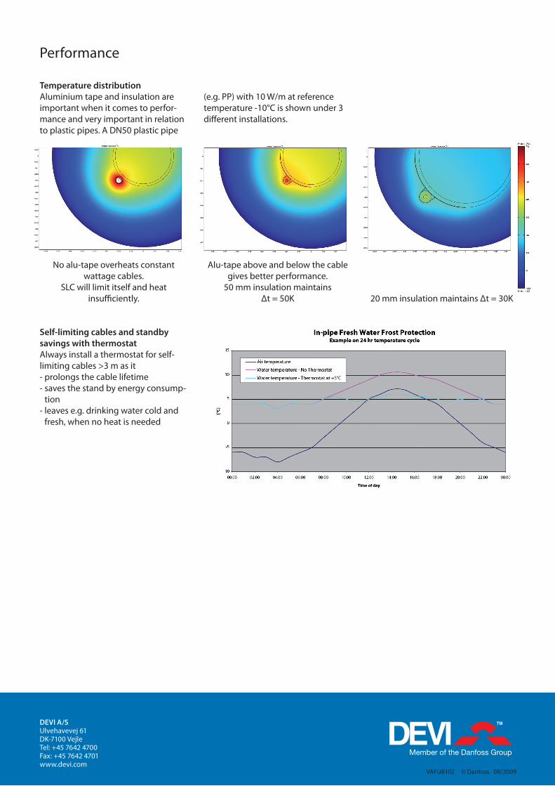
Temperature distribution Aluminium tape and insulation are important when it comes to perfor-mance and very important in relation to plastic pipes. A DN50 plastic pipe
(e.g. PP) with 10 W/m at reference temperature -10°C is shown under 3 different installations.
Self-limiting cables and standby savings with thermostat Always install a thermostat for self-limiting cables >3 m as it- prolongs the cable lifetime - saves the stand by energy consump-
tion- leaves e.g. drinking water cold and
fresh, when no heat is needed
No alu-tape overheats constant wattage cables.
SLC will limit itself and heat insufficiently.
Alu-tape above and below the cable gives better performance.
50 mm insulation maintains Δt = 50K 20 mm insulation maintains Δt = 30K
VAFUB102 © Danfoss 08/2009