Embed Size (px)
Citation preview
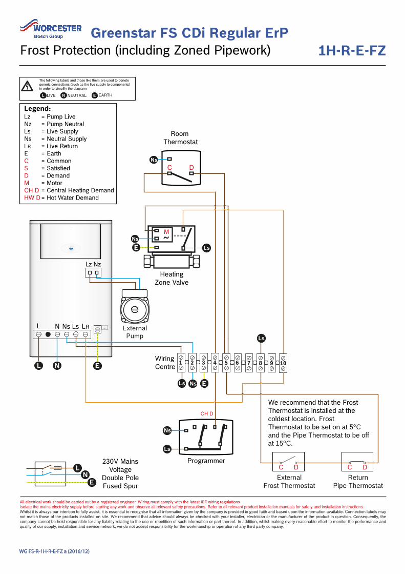
Greenstar FS CDi Regular ErP1H-R-E-FZ
All electrical work should be carried out by a registered engineer. Wiring must comply with the latest IET wiring regulations. Isolate the mains electricity supply before starting any work and observe all relevant safety precautions. Refer to all relevant product installation manuals for safety and installation instructions. Whilst it is always our intention to fully assist, it is essential to recognise that all information given by the company is provided in good faith and based upon the information available. Connection labels may not match those of the products installed on site. We recommend that advice should always be checked with your installer, electrician or the manufacturer of the product in question. Consequently, the company cannot be held responsible for any liability relating to the use or repetition of such information or part thereof. In addition, whilst making every reasonable effort to monitor the performance and quality of our supply, installation and service network, we do not accept responsibility for the workmanship or operation of any third party company.
WG FS-R-1H-R-E-FZ a (2016/12)
Frost Protection (including Zoned Pipework)
L LIVE N NEUTRAL EARTHE
The following labels and those like them are used to denote generic connections (such as the live supply to components) in order to simplify the diagram:
Wiring Centre
Programmer
~E
Room Thermostat
ExternalFrost Thermostat
C DReturn
Pipe Thermostat
C D
CH D
E
HeatingZone Valve
230V MainsVoltage
Double PoleFused Spur
NsC D
NsLs
Ls Ns
Ns
Ls
L N E
Legend:LzNzLsNsLRECSDMCH DHW D
= Pump Live= Pump Neutral= Live Supply= Neutral Supply= Live Return= Earth= Common= Satisfied= Demand= Motor= Central Heating Demand= Hot Water Demand
Ls
1 2 3 4 5 7 8 9 106
We recommend that the Frost Thermostat is installed at the coldest location. Frost Thermostat to be set on at 5°C and the Pipe Thermostat to be off at 15°C.
L N Ns Ls LR
LN
E
ExternalPump
Lz Nz
Programmer
~E
~E
Room Thermostat
Zone 1
CH1 D CH2 D
E
HeatingZone 2 Valve
HeatingZone 1 Valve
ExternalPump
1 2 3 4 5 7 8 9 106
NsC D
NsLs
Ns
Ls
Ls Ns
Ns
Ls
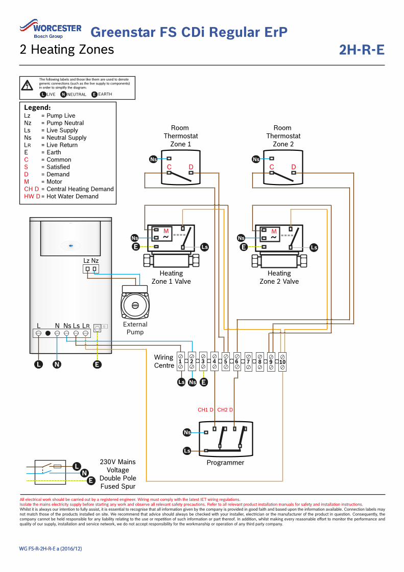
Legend:LzNzLsNsLRECSDMCH DHW D
= Pump Live= Pump Neutral= Live Supply= Neutral Supply= Live Return= Earth= Common= Satisfied= Demand= Motor= Central Heating Demand= Hot Water Demand
Room Thermostat
Zone 2
NsC D
L N E
Lz Nz
L N Ns Ls LR
230V MainsVoltage
Double PoleFused Spur
LN
E
Wiring Centre
Greenstar FS CDi Regular ErP2H-R-E
All electrical work should be carried out by a registered engineer. Wiring must comply with the latest IET wiring regulations. Isolate the mains electricity supply before starting any work and observe all relevant safety precautions. Refer to all relevant product installation manuals for safety and installation instructions. Whilst it is always our intention to fully assist, it is essential to recognise that all information given by the company is provided in good faith and based upon the information available. Connection labels may not match those of the products installed on site. We recommend that advice should always be checked with your installer, electrician or the manufacturer of the product in question. Consequently, the company cannot be held responsible for any liability relating to the use or repetition of such information or part thereof. In addition, whilst making every reasonable effort to monitor the performance and quality of our supply, installation and service network, we do not accept responsibility for the workmanship or operation of any third party company.
WG FS-R-2H-R-E a (2016/12)
2 Heating Zones
L LIVE N NEUTRAL EARTHE
The following labels and those like them are used to denote generic connections (such as the live supply to components) in order to simplify the diagram:
Greenstar FS CDi Regular ErP------FB
All electrical work should be carried out by a registered engineer. Wiring must comply with the latest IET wiring regulations. Isolate the mains electricity supply before starting any work and observe all relevant safety precautions. Refer to all relevant product installation manuals for safety and installation instructions. Whilst it is always our intention to fully assist, it is essential to recognise that all information given by the company is provided in good faith and based upon the information available. Connection labels may not match those of the products installed on site. We recommend that advice should always be checked with your installer, electrician or the manufacturer of the product in question. Consequently, the company cannot be held responsible for any liability relating to the use or repetition of such information or part thereof. In addition, whilst making every reasonable effort to monitor the performance and quality of our supply, installation and service network, we do not accept responsibility for the workmanship or operation of any third party company.
WG FS-R-------FB a (2016/12)
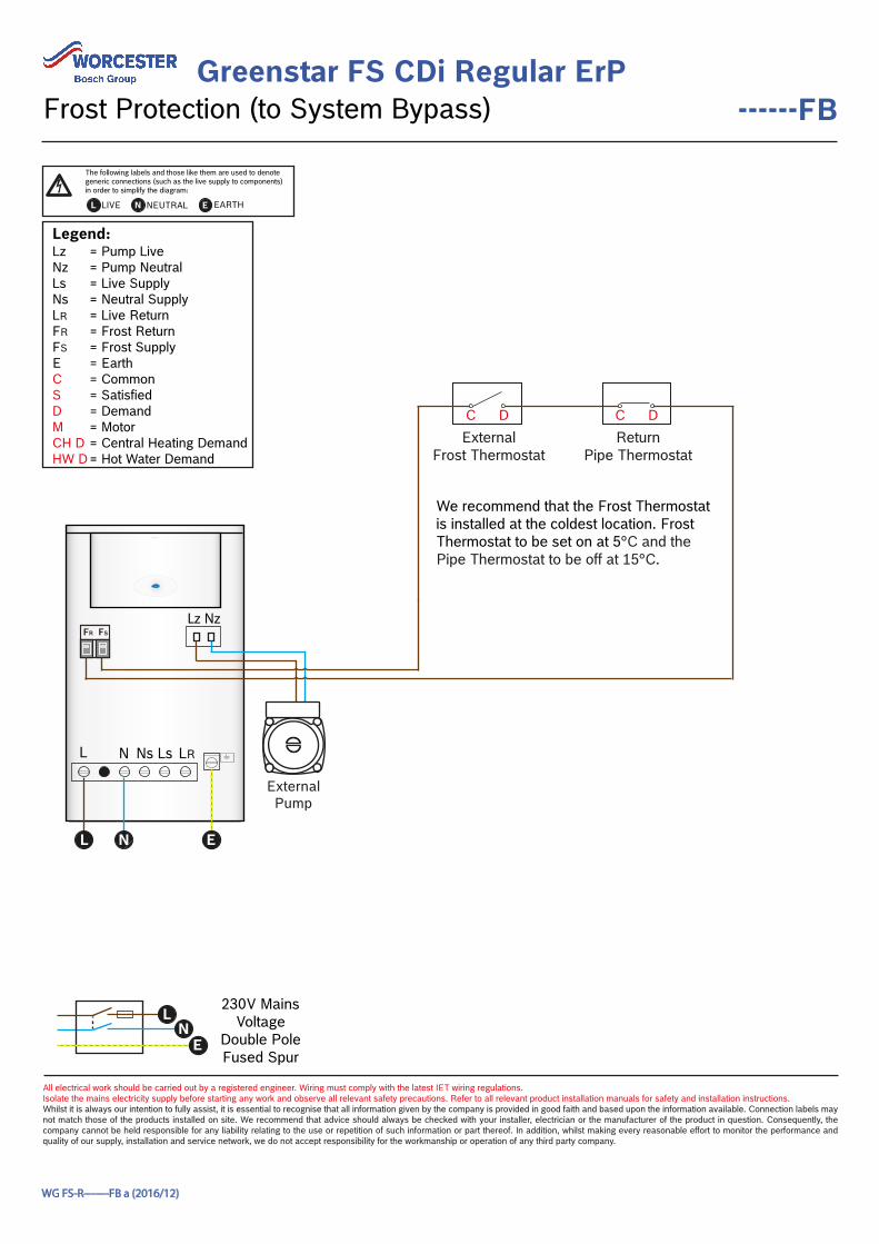
Frost Protection (to System Bypass)
L LIVE N NEUTRAL EARTHE
The following labels and those like them are used to denote generic connections (such as the live supply to components) in order to simplify the diagram:
230V MainsVoltage
Double PoleFused Spur
Legend:LzNzLsNsLRFR FS ECSDMCH DHW D
= Pump Live= Pump Neutral= Live Supply= Neutral Supply= Live Return= Frost Return= Frost Supply = Earth= Common= Satisfied= Demand= Motor= Central Heating Demand= Hot Water Demand
FSFR
ExternalFrost Thermostat
C DReturn
Pipe Thermostat
C D
We recommend that the Frost Thermostat is installed at the coldest location. Frost Thermostat to be set on at 5°C and the Pipe Thermostat to be off at 15°C.
LN
E
L N Ns Ls LR
L N E
ExternalPump
Lz Nz
Greenstar FS CDi Regular ErP------LLH
All electrical work should be carried out by a registered engineer. Wiring must comply with the latest IET wiring regulations. Isolate the mains electricity supply before starting any work and observe all relevant safety precautions. Refer to all relevant product installation manuals for safety and installation instructions. Whilst it is always our intention to fully assist, it is essential to recognise that all information given by the company is provided in good faith and based upon the information available. Connection labels may not match those of the products installed on site. We recommend that advice should always be checked with your installer, electrician or the manufacturer of the product in question. Consequently, the company cannot be held responsible for any liability relating to the use or repetition of such information or part thereof. In addition, whilst making every reasonable effort to monitor the performance and quality of our supply, installation and service network, we do not accept responsibility for the workmanship or operation of any third party company.
WG FS-R-------LLH a (2016/12)
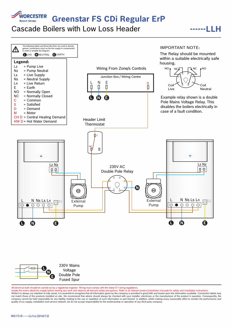
Cascade Boilers with Low Loss Header
L LIVE N NEUTRAL EARTHE
The following labels and those like them are used to denote generic connections (such as the live supply to components) in order to simplify the diagram:
230V MainsVoltage
Double PoleFused Spur
L N Ns Ls LR
L N E L N E
Legend:LzNzLsNsLRENONCCSDMCH DHW D
= Pump Live= Pump Neutral= Live Supply= Neutral Supply= Live Return= Earth= Normally Open= Normally Closed= Common= Satisfied= Demand= Motor= Central Heating Demand= Hot Water Demand
IMPORTANT NOTE:The Relay should be mountedwithin a suitable electrically safehousing.
C C
NO NC
Coil Neutral
NONC
Coil Live
Example relay shown is a doublePole Mains Voltage Relay. Thisdisables the boilers electrically incase of a fault condition.
Junction Box / Wiring Centre
L N E
Wiring From Zone/s Controls
C
NC
Header Limit Thermostat
230V ACDouble Pole Relay
C C
D
N
ELs
LN
E
L N Ns Ls LR
L N
ExternalPump
ExternalPump
Lz Nz Lz Nz
~E
~E
Room Thermostat
Zone 1C
S D
CylinderThermostat
Programmer 3 Channel
CH1 D HW D
E
Cylinder Zone Valve
HeatingZone 1 Valve
230V MainsVoltage
Double PoleFused Spur
ExternalPump
1 2 3 4 5 7 8 9 106
NsC D
NsLs
Ns
Ls
Ls Ns
Ns
Ls
Legend:LzNzLsNsLRECSDMCH DHW D
= Pump Live= Pump Neutral= Live Supply= Neutral Supply= Live Return= Earth= Common= Satisfied= Demand= Motor= Central Heating Demand= Hot Water Demand
~E
HeatingZone 2 Valve
Ns
Ls
Room Thermostat
Zone 2
NsC D
CH2 D
L N Ns Ls LR
Lz Nz
L N E
LN
E
Wiring Centre
Greenstar FS CDi Regular ErPP-R-E
All electrical work should be carried out by a registered engineer. Wiring must comply with the latest IET wiring regulations. Isolate the mains electricity supply before starting any work and observe all relevant safety precautions. Refer to all relevant product installation manuals for safety and installation instructions. Whilst it is always our intention to fully assist, it is essential to recognise that all information given by the company is provided in good faith and based upon the information available. Connection labels may not match those of the products installed on site. We recommend that advice should always be checked with your installer, electrician or the manufacturer of the product in question. Consequently, the company cannot be held responsible for any liability relating to the use or repetition of such information or part thereof. In addition, whilst making every reasonable effort to monitor the performance and quality of our supply, installation and service network, we do not accept responsibility for the workmanship or operation of any third party company.
WG FS-R-P-R-E a (2016/12)
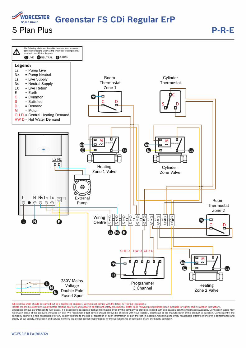
S Plan Plus
L LIVE N NEUTRAL EARTHE
The following labels and those like them are used to denote generic connections (such as the live supply to components) in order to simplify the diagram:
Greenstar FS CDi Regular ErPP-U-E
All electrical work should be carried out by a registered engineer. Wiring must comply with the latest IET wiring regulations. Isolate the mains electricity supply before starting any work and observe all relevant safety precautions. Refer to all relevant product installation manuals for safety and installation instructions. Whilst it is always our intention to fully assist, it is essential to recognise that all information given by the company is provided in good faith and based upon the information available. Connection labels may not match those of the products installed on site. We recommend that advice should always be checked with your installer, electrician or the manufacturer of the product in question. Consequently, the company cannot be held responsible for any liability relating to the use or repetition of such information or part thereof. In addition, whilst making every reasonable effort to monitor the performance and quality of our supply, installation and service network, we do not accept responsibility for the workmanship or operation of any third party company.
WG FS-R-P-U-E a (2016/12)
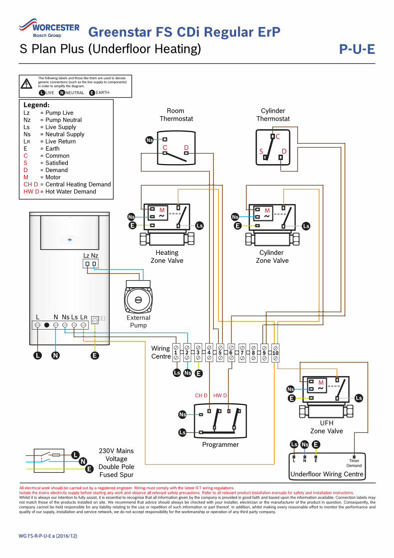
S Plan Plus (Underfloor Heating)
L LIVE N NEUTRAL EARTHE
The following labels and those like them are used to denote generic connections (such as the live supply to components) in order to simplify the diagram:
Wiring Centre
Programmer
~E
~E
Room Thermostat
C
S D
CylinderThermostat
CH D HW D
E
Cylinder Zone Valve
HeatingZone Valve
230V MainsVoltage
Double PoleFused Spur
Lz Nz
ExternalPump
1 2 3 4 5 7 8 9 106
NsC D
NsLs
Ns
Ls
Ls Ns
Ns
Ls
Legend:LzNzLsNsLRECSDMCH DHW D
= Pump Live= Pump Neutral= Live Supply= Neutral Supply= Live Return= Earth= Common= Satisfied= Demand= Motor= Central Heating Demand= Hot Water Demand
~
UFHZone Valve
ENs
Ls
L N Ns Ls LR
EL N
Underfloor Wiring Centre
L N E TimerDemand
ELs Ns
LN
E
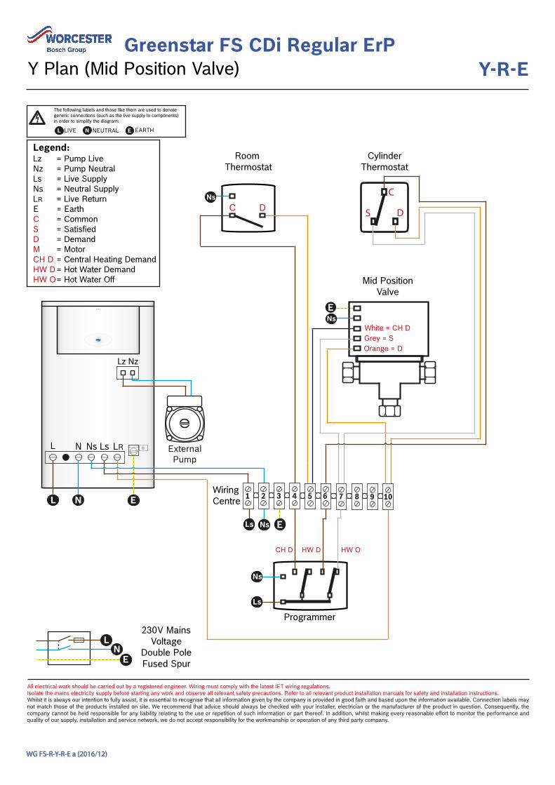
Greenstar FS CDi Regular ErPY-R-E
All electrical work should be carried out by a registered engineer. Wiring must comply with the latest IET wiring regulations. Isolate the mains electricity supply before starting any work and observe all relevant safety precautions. Refer to all relevant product installation manuals for safety and installation instructions. Whilst it is always our intention to fully assist, it is essential to recognise that all information given by the company is provided in good faith and based upon the information available. Connection labels may not match those of the products installed on site. We recommend that advice should always be checked with your installer, electrician or the manufacturer of the product in question. Consequently, the company cannot be held responsible for any liability relating to the use or repetition of such information or part thereof. In addition, whilst making every reasonable effort to monitor the performance and quality of our supply, installation and service network, we do not accept responsibility for the workmanship or operation of any third party company.
WG FS-R-Y-R-E a (2016/12)
Y Plan (Mid Position Valve)
L LIVE N NEUTRAL EARTHE
The following labels and those like them are used to denote generic connections (such as the live supply to components) in order to simplify the diagram:
Programmer
Room Thermostat
C
S D
CylinderThermostat
CH D HW D
E
230V MainsVoltage
Double PoleFused Spur
E 1 2 3 4 5 7 8 9 106
NsC D
Ls Ns
Ns
Ls
Legend:LzNzLsNsLRECSDMCH DHW DHW O
= Pump Live= Pump Neutral= Live Supply= Neutral Supply= Live Return= Earth= Common= Satisfied= Demand= Motor= Central Heating Demand= Hot Water Demand= Hot Water Off Mid Position
Valve
NsE
HW O
Orange = DGrey = SWhite = CH D
L N
LN
E
L N Ns Ls LR ExternalPump
Lz Nz
Wiring Centre