Embed Size (px)
Citation preview

Front Shock Conversion Kit, 1962-1980 MGB
A thesis submitted to the Faculty of the Mechanical Engineering Technology Program
of the University of Cincinnati in partial fulfillment of the
requirements for the degree of
Bachelor of Science
in Mechanical Engineering Technology at the College of Engineering & Applied Science
by
MATT KASER
Bachelor of Science University of Cincinnati
May 2011
Faculty Advisor: Professor Caldwell

ABSTRACT
The MGB is a British sports car made from 1962 to 1980. In the 18 years that these cars were manufactured the main components remained unchanged. Roughly half a million MGB’s were made. Current owners are faced with high cost to replace components that are no longer being manufactured. One of these components is the front shocks on the car. The shocks are a hydraulic lever arm shock that cost roughly $250 to $300 each (two required per car) for a rebuilt unit. A new cost effective alternative to these would be a gas shock conversion kit. This kit would allow the MGB owner to bolt on brackets and a modern gas shock to replace the hydraulic lever arm shock.
Those surveyed stated that cost and performance were the top areas of concern. Taking this information and engineering analysis gave two different options. Both options were looked at using engineering design tools. The swivel mechanism assembly was selected as the best option.
Shock dampening was calculated based on the original MGB shock dampening and the weight of the car. Increasing the dampening force resulted in a firmer sportier ride with less body roll around turns. The brackets were analyzed with linear forces to make sure they would hold up to everyday use. The rating of the shock was 3600N on compression and 1800N on the rebound.
The design of the components would allow quick cost effective manufacturing. The components were all made from two common thicknesses’ (.375” and .75”) and manufactured using a wire edm machine. Very little secondary operation were required and everything bolted together
The assembly assembles using common hand tools with no modifications needed to the car, everything is bolt on. The cost of the kit would be around $300 compared to two rebuilt original shocks at $500 to $600.

II
TABLE OF CONTENTS
ABSTARCT ......................................................... ERROR! BOOKMARK NOT DEFINED.
TABLE OF CONTENTS .......................................................................................................... II
LIST OF FIGURES ............................................................................................................... IIII
LIST OF TABLES ................................................................................................................. IIII
INTRODUCTION ............................................... ERROR! BOOKMARK NOT DEFINED.
BACKGROUND ....................................................................................... ERROR! BOOKMARK NOT DEFINED.
FACTORY REPLACEMENT .................................................................................................................................... 2
AFTERMARKET REPLACEMENT ............................................................................................................................ 3
CUSTOMER FEEDBACK,FEATURES, AND OBJECTIVES .............................................. 4
SURVEY ANALYSIS ....................................................................................................................................... 4 PRODUCT FEATURES AND OBJECTIVES .................................................................................................. 5
CONCEPT GENERATION AND SELECTION ..................................................................... 6
REUSE EXISTING SHOCK ............................................................................................................................. 6
SWIVEL MECHANISM ................................................................................................................................... 7
DESIGN .................................................................................................................................... 8
CALCULATING THE NEEDED TRAVEL FOR THE SHOCK ...................................................................... 8
SHOCK DAMPENING CALCULATIONS ...................................................................................................... 9
STRESS ANAYLSIS CALCULATIONS ......................................................................................................... 9
THE ASSEMBLY DESIGN DETAILS ............ ERROR! BOOKMARK NOT DEFINED.3
DRAWINGS .................................................................................................................................................... 15
SURFACE TREATMENT OF PARTS ........................................................................................................... 15
FABRICATION…………………………………………………………………………………………...….15
SCHEDULE ............................................................................................................................ 16
BUDGET………………………………………………………………………………… 17
TESTING ........................................................... ERROR! BOOKMARK NOT DEFINED.7
CONCLUSION ....................................................................................................................... 18
REFERENCES ....................................................................................................................... 19
APPENDIX A: MGB SHOCK REFERANCES.................................................................... A1
APPENDIX B: CUSTOMER SURVEY AND RESULTS .................................................... B1
APPENDIX C: QUALIITY FUNCTION DEPLOYMENT ANALYSIS .............................. C1
APPENDIX D: SCHEDULE ................................................................................................. D1
APPENDIX E: BUDGET………………………………………………………...…………E1
APPENDIX F: DRAWINGS…………………………………………………...………...…F1
APPENDIX G: INSTRUCTION MANUAL ……………………………………………….G1

II
LIST OF FIGURES Figure 1- MGB 1
Figure 2- Stock Lever Arm Shock 2
Figure 3- Aftermarket Shock Kit 3
Figure 4– Existing Suspension Setup 6
Figure 5– Concept 1 Reusing the existing shock for a mechanism 7
Figure 6– Concept 2 –Swivel Mechanism 7
Figure 7– Shock Stroke Measurement 8
Figure 8– Fixed Support Upper Bracket 10
Figure 9– Force Vector Upper Bracket 10
Figure 10– Max Stress Upper Bracket 11
Figure 11– Fixed Support Lower Bracket 11
Figure 12– Force Vector Lower Bracket 12
Figure 13– Max Stress Lower Bracket 12
Figure 14– Lower Bracket Assembly View 14
Figure 15– Upper Bracket Assembly View 15
Figure 16– Swivel Device Assembly View 16
LIST OF TABLES Table 1- Weighted Importance 4
Table 2-Weighted Decision Matrix 8
Table 3-Shock Comparison 9

1962 TO 1980 MGB FRONT SHOCK CONVERSION KIT MATT KASER
1
INTRODUCTION
BACKGROUND
The 1962 to 1980 MGB’s were manufactured in England by BMC and then British Leyland.
The original design stayed the same throughout the 18 year span, only making minor body
changes and interior. These cars where equipped with a front shock system that was called
Lever Hydraulics. They are a very old design that dates back to the early fifties. They use the
concept of a two levers that attach to the bottom plate on the front suspension on both front
wheels.
Figure 1- MGB
Due to the age and original design of these units, they need replaced or rebuilt. Two rebuilt
units cost about $500. There is only one company that rebuilds them. What is needed is
making an aftermarket modern gas shock system. This will greatly improve ride quality and
also be much cheaper to replace. In retrofitting an aftermarket unit, the brackets will be
bolted to existing mounts of the lever shock on the body of the car and also brackets to attach
to the bottom of the suspension. These brackets will use existing mounting holes and to
achieve the correct angles for the shock to work correctly.
The correct gas shock will also go with the weight and dampening force of the car. The
brackets will have to hold up to tough road condition such as motocross or spirited driving.
They will have to be stress analyzed for durability. The assembly will also have to hold up to
road condition that involves rain, salt and normal driving road debris. The key would be to
build and manufacture the complete assembly for less than $250 to price the item in the low
$300 range. This would make it a very attractive alternative to rebuilt units.

1962 TO 1980 MGB FRONT SHOCK CONVERSION KIT MATT KASER
2
EXISTING PRODUCTS
FACTORY REPLACEMENTS
The largest catalog part store for old British sports cars is called Moss Motors; they offer
a factory replacement for the front shocks (Figure 2) (Reference 2). Figure 2 below shows a
picture of what the existing lever arm hydraulic shock looks like. This is a new lever arm
hydraulic shock. This shock is exactly what came on the cars when new. This will return the
front shocks to a new condition. They retail for $239.95 each. (See Appendix A for full
details)
Figure 2- Stock Lever Arm shock
Moss Motors also offers a rebuilt unit. They take worn out existing stock units and
rebuild them to factory specifications. The cost for these is $199.95 each but requires a $75
core charge for the existing shocks that are on your car. (Reference 3)
These shocks require you to fill them up with hydraulic fluid before you use them and
also do require some checking of the fluid routinely.
These two options are what most MGB car owners go with. It provides a direct
replacement component that matches what the car original came with. The downside to these
is the price, performance and availability. It has been 30 years since the last car was built and
part sources are slowly drying up. A brand new unit will cost a MGB car owner $480 plus
shipping and a rebuilt unit will cost $400 plus shipping and shipping back the old shocks.
The design or the lever type shocks dates back to the 1950’s this type of shock was quickly
replaced by the more efficient gas shock.
Existing Shock
Kingpin

1962 TO 1980 MGB FRONT SHOCK CONVERSION KIT MATT KASER
3
AFTERMARKET REPLACEMENT
The other choice for replacement shocks is to go with the gas shock conversion kit.
Moss Motors also sells this kit (See figure 2) they sell this kit for $509.95 and comes with
everything needed to change over from the original lever arm shocks to gas shocks. There are
a few problems with this kit. One is the price of the kit, at $509.95 it makes it more than
going with the brand new factory replacements. The big issue with this kit that makes MGB
car owners hesitant to go with it is that you must leave the factory lever arm shock on the car
because it provides the swivel point for the kingpins which is transferred to the front
wheels(See Figure 3)(Referance 4). They instruct you to drain the hydraulic fluid out of the
original shock to essential make there dampening factor nonexistent. (See Appendix A for
full details)
Figure 3 – Aftermarket Shock Kit (REFERANCE 4)
These are the only two options a 1962 to 1980 MGB car owner has when replacing there
front shocks. Neither option are very cost effective considering new gas shocks for smaller
car run about $100 each.

1962 TO 1980 MGB FRONT SHOCK CONVERSION KIT MATT KASER
4
CUSTOMER FEEDBACK, FEATURES, AND OBJECTIVES
-
SURVEY ANALYSIS
The customer surveys were returned and analyzed to determine the customer’s needs.
The surveys were completed by 4 different generation MGB owners. The cars that the
surveys each had were 1964 MGB, a 1970 MGB, a 1977 MGB and a 1980 MGB. This gave
a general look at each other through the life span of the MGB (1962 to 1980). (See Appendix
B for full survey and customer results). The survey included a wide range of product features
arranged in categories of operation/function, maintenance, and cost. The first half of the
survey focused on customer importance as the surveyors were asked to rate the importance of
features on a scale from 1-5 with 5 being the most important. The results in the table have
been sorted from most important to least important.
Table 1-Weighted Importance
The survey results show that the top three customer features was performance, price and
reliability. The customer features of appearance and ease of installation were ranked at the
bottom of the list. Engineering characteristics were used to judge each category. Dampening
method, Installation Time and Material were the top 3 categories. Dampening method
referred to how the kit would dampening the front suspension of the car. Installation time
referred to how easy the kit was to install on the car and what if any modifications were
needed to the suspension. Material hit almost all of the customer features and impacted just
how the kit would be designed and built.
The designer multiplier was added to price of 1.1. Price was the top important feature to
have a very successful product. The price had to be below competitors’ products. A low cost
but quality kit that will function to give the customer the reliability and performance needed
will be far superior to the existing options on the market. The design and build aspects of the
Custo
mer
import
ance
Desig
ner's M
ultip
lier
Curr
ent
Satisfa
ction
Pla
nned S
atisfa
ction
Impro
vem
ent
ratio
Modifie
d I
mport
ance
Rela
tive w
eig
ht
%Price 4.25 1.1 2.25 5 2.22 10.39 24.0
Performance 4.70 1 3.25 4 1.23 5.78 13.0
Realibilty 4.25 1 3.3 4 1.21 5.15 12.0
Availibilty of the Kit 4.00 1 3.3 4 1.21 4.85 11.0
Durability 3.95 1 3.7 4 1.08 4.27 10.0
Ease of Installation 3.30 1 3.25 4 1.23 4.06 9.0
Safety 4.01 1 4 4 1.00 4.01 9.0
Range of Operation 3.25 1 4.25 4 0.94 3.06 7.0
Appearance 3.00 1 4 3 0.75 2.25 5.0

1962 TO 1980 MGB FRONT SHOCK CONVERSION KIT MATT KASER
5
conversion kit will take these customer features into account. The unique design of the
product will keep the cost down; the components will have common thicknesses (all cut out
of 2 common metal flat plates), require very little secondary operations and require no
welding. They will bolt together in a peg and slot design that will help location and the
strength of the brackets.
PRODUCT FEATURES AND OBJECTIVE
The product objectives come straight from the list of customer features determined
from the survey. These customer features were cross-referenced with engineering
characteristics and rated for a strong to weak correlation. The list below ranks the features in
order of customer importance followed in parentheses by the average response in the
customer survey. Below each feature is the engineering characteristic followed by the
method or objective that will be used for the prototype design.
These product objectives will be delivered from a product that will convert the MGB
front lever arm Hydraulic shocks to Gas shocks. These product features and objectives are:
Price (24%):
1.) The conversion kit will cost less than $300 to purchase.
2.) The material of the brackets will be made of standard plate steel(4130 CRS or
equivalent)
Performance (13%):
1.) The conversion kit will have the proper Hertz rating (on the shocks) to achieve
optimal ride conditions.
Reliability (12%):
1.) The kit will be made to allowable machining tolerances so that each kit will fit with
allowable assembly tolerances.
2.) The shocks chosen will have a lifespan of a minimum of 30,000 miles.
Availability of the kit (11%):
1.) The kit will be available to the customer at order time. The lead time to manufacture
a kit will allow at least one in stock so that the customer will not have to wait to receive
the kit.
2.) The kits will all be standard and no changes will be needed from one kit to another.
Durability (10%):
1.) Durability of the brackets and shocks measured by component life and proper design
criteria
2.) The metal brackets will have a coating or paint to protect them from corroding due to
adverse weather conditions while driving the car. (Water, Salt, etc.).
3.) Mechanical assembly will follow allowable torques of mechanical fasteners
4.) The material will be a Standard Steel to withstand fatigue (4130 CRS or equivalent)

1962 TO 1980 MGB FRONT SHOCK CONVERSION KIT MATT KASER
6
Safety (9%): 1.) A factor of safety (Mott) will be provided by Anysys analysis software to show that
the structural components will not fail under repeated shock load.
2.) All hardware (bolts, washers, nuts, etc) will be fastened with correct torque ratings.
Ease of Installation (9%):
1.) The kit will be able to be installed by anybody with general car repair knowledge and
basic hand tools.
2.) It will not require any modifications to the existing suspension structure
a. No welding of brackets
b. No drilling of additional holes
c. No cutting or grinding of existing suspension or body components
Range of Operation (7%):
1.) The shock will be able to travel the needed distance to allow the wheel to move in
the factory range of motion.
Appearance (5%):
1.) The shocks and brackets will look like a component that was installed at the factory
2.) The brackets and bolts will have a coating/paint so they are weather resistant
CONCEPT GENERATION AND SELECTION
REUSE EXISTING SHOCK The first concept shown in figure 5 will be referred as the Reusing Existing shock
design. The existing shock works as a mechanism for the suspension of the car. It attaches to
the kingpin with rides up and down as the car goes over bumps and low spots (see figure 4).
The kit would bolt on to the existing bolts holes used by the shock for the top bracket and
holes that hold the lower pan for the bottom bracket. The customer would have to drain the
hydraulic fluid out of the shock and bolt it down on top of the bracket.
Figure 4– Existing Suspension Setup
Existing Shock

1962 TO 1980 MGB FRONT SHOCK CONVERSION KIT MATT KASER
7
Figure 5– Concept 1 –Reusing the existing shock for a mechanism
SWIVEL MECHANISM The second concept shown below in Figure 6 is the Swivel Mechanism. This concept
uses two bars; they replace the arms of the old shock, which connect to the kingpin of the
cars suspension. The two arms will pivot in a post that has bearing in it. This will allow the
suspension to still correctly move up and down as if the original shock was still on the car.
The brackets and shock are exactly the same as the Reuse Existing shock concept.
Figure 6– Concept 2 –Swivel Mechanism
The two concepts were evaluated using a weighted decision matrix using a ten-point scale.

1962 TO 1980 MGB FRONT SHOCK CONVERSION KIT MATT KASER
8
The scores range from zero being inadequate to 10 being superior. The weight was used from
the product features. The scores are so close that either design could be picked. The two
highest factors of price and performance made the difference up in choosing the Swivel
Device concept over the Reuse Existing Shock Concept.
Table 2-Weighted Decision Matrix
DESIGN
CALCULATION THE NEEDED TRAVEL FOR THE SHOCK The design will use a gas shock that will have a compressed length and an extended
length. In order to figure what was needed measurements were taken on the car to get the
travel. To get the compressed length of the shock, I measured from the distance from the
bump stop to the bottom pan with the car on the ground. This dimension was 2.75”. Next I
measured the same spot but with the front of the car in the air. This allowed me to get the
maximum extended length. That number was 4.50”. This means that the total travel that I
need is 4.50”. I then took measurements from the bottom mounting point of the bracket to the
base where the existing shock sits (where my new upper bracket will bolt on to). The shock I
choose had a max extended length of 14.250”. I designed the top brackets around this length.
Figure 7– Shock Stroke Measurement
SHOCK DAMPENING CALCULATIONS
Reuse Existing Shock Swivel Device
Features Weight Rating Score Rating Score
Price 0.24 9 2.134 7 1.659
Performance 0.13 5 0.660 7 0.924
Reliability 0.12 6 0.705 8 0.940
Availability 0.11 8 0.885 7 0.774
Durability 0.10 8 0.780 7 0.682
Ease of Installation 0.09 6 0.556 8 0.741
Safety 0.09 7 0.641 8 0.732
Range of Operation 0.07 8 0.558 8 0.558
Appearance 0.05 7 0.359 6 0.308
Total 6.360 Total 6.454
Bump Stop
Distance Measured

1962 TO 1980 MGB FRONT SHOCK CONVERSION KIT MATT KASER
9
Shock dampening is rated with two numbers, example is 360/180. The first number is
the rebound force in Newton’s and the second number is the compression force in Newton’s.
Shock dampening is different from each type of shock. Manufactures consider there
dampening values to be confidential information. The shocks had to be cross referenced to
get an idea of which one to choose. The first step is taking choosing one that has enough
travel and will fit one the car. The shock had to be a loop mount on top and bottom to allow it
to attach easily to the mounting brackets. This narrowed the shock choices down. The final
criteria used to narrow down the selection was weight. Compared the vehicle in which the
shock was made for to the weight of the MGB.
The shock that was chosen was the Monroe Sensa-tracs Gas shock # 5893 which was
used on front of 1984-1986 Dodge Colt Hatchback, similar car in weight (1900lbs compared
to MGB 1940lbs). This shock had a compressed length 9.375, extended length 14.250 and total
travel 4.875. Contacting Monroe on the phone, they gave me the rating for these shocks at 360/180.
(Reference 5) See Table 3 for the comparison of the Monroe 5893 to the original MGB shock
(Reference 6). The Monroe Sensa-Tracs Gas shock #5983 is comparable and gives a firmer, sportier
ride (reduce body roll). These shocks are rated to last 50,000 miles. (Reference 5)
Shock Type Monroe 5893 Original MGB
Rebound Force Rating 809LbF (3600N) 725LbF
Compression Force Rating 404LbF (1800N) 350LbF
Table 3-Shock Comparison
STRESS ANAYLSIS CALCULATIONS
The upper and lower brackets were analyzed to see if they could withstand the force
vectors put on them during driving condition using Ansys analysis software. The material of
the bracket is 4340 Steel. It is in normalized condition with tensile yield strength of 125,000
PSI. (Reference 7) The automotive standard for safety factor is 3.0(reference 8). This would
give me an allowable stress of 41,666 PSI.
For the analysis the upper and lower bracket had a force of 809LB put on the
mounting point of the shock. The 809LBF comes from the max rebound force rated for the
shock; the compression force was less at 404LBF so it was not analyzed. The direction of the
force vector was perpendicular to the brackets, the same direction that the shock will travel as
it compresses and rebounds. The brackets were fixed by the points that were going to be
actually bolted to the existing suspension.

1962 TO 1980 MGB FRONT SHOCK CONVERSION KIT MATT KASER
10
Figure 8– Fixed Support Upper Bracket
Figure 9– Force Vector Upper Bracket
Fixed Support placed at
bottom of bracket
Force Vector of
809LB

1962 TO 1980 MGB FRONT SHOCK CONVERSION KIT MATT KASER
11
Figure 10– Max Stress Upper Bracket
Figure 11– Fixed Support Lower Bracket
Fixed Support placed at side of
bracket
29,571 PSI Max Stress,
Which is under the max
allowable stress of
41,666 PSI. Factory of
Safety of 3.0

1962 TO 1980 MGB FRONT SHOCK CONVERSION KIT MATT KASER
12
Figure 12– Force Vector Lower Bracket
Figure 13– Max Stress Lower Bracket
Force Vector of
809LB
17,592 PSI Max Stress,
under the max allowable
stress 41,666 PSI,
Factory of Safety of 3.0

1962 TO 1980 MGB FRONT SHOCK CONVERSION KIT MATT KASER
13
THE ASSEMBLY DESIGN DETAILS
The components of the assembly were designed to work with the existing suspension on
the car. The upper and lower brackets were designed around existing bolt holes on the
suspension to allow easy installation without any modifications to the car. The hardware used
is standard off the shelf sizes.
The lower bracket is a very simple design with two mounting holes and a 3/8-16
Threaded hole for mounting of the shock. The threaded hole is at an angle to compensate for
the angle that is in the lower suspension arm on the car.
Figure 14– Lower Bracket Assembly View
The lower bracket uses the holes
in the bottom suspension arm of
the car to mount
Bolt that attaches the shock to the
lower bracket at an angle to
match the angle in the lower
suspension arm

1962 TO 1980 MGB FRONT SHOCK CONVERSION KIT MATT KASER
14
The upper bracket uses the existing 4 mounting holes that the old hydraulic shock used.
It is a two piece design that is tabbed in to ensure that it does not move and to achieve correct
orientation for the 90 degree angle. The two pieces are bolted together using ¼-20 socket
head cap screws. The top bracket is where the top eyelet of the shock mounts to a 3/8-16
thread, the position of this hole incorporates the needed length that is required for the Monroe
Sensa Trac shock that was chosen.
The swivel device that replace the upper and down movement control that the old shock
provided, will be tabbed and bolted to the upper bracket as well.
Figure 15– Upper Bracket Assembly View
Holes that will be used to mount
the bracket to the old shock
mounting point
Tabbed and bolted together to
from the 90 degree angle required

1962 TO 1980 MGB FRONT SHOCK CONVERSION KIT MATT KASER
15
The swivel device is needed because the original hydraulic shock not only worked as a
dampener but also a mechanism to allow the suspension to go up and down as the car drove
over uneven surfaces. The arms of the device were designed around the original arms on the
hydraulic shock; they are similar dimension to the original arms. The arms swivel about a
post that is attached to the upper bracket. In the post there are two ball bearings that are
pressed into bores in the post. The arms are bolted to the center post using the shoulder bolt,
washers and a nylon thread lock metal nut, the shoulder bolt rides on the bearings allowing
the arms to rotate up and down freely.
Figure 16– Swivel Device Assembly View
DRAWINGS Assembly, Bill of Material and details drawings provide complete specifications for the
product including material selections, geometric dimensioning and tolerancing, Refer to
Appendix E for product drawings.
SURFACE TREATMENT OF PARTS All metal components will be painted flat black to protect them from corroding. All
hardware will have the standard finish that come with them.
FABRICATION All components were made from flat 4340 plate steel. The components were designed to
keep a uniform thickness, only two different thicknesses were needed. One was .375 and the
other was .75. The parts were cut on a wire edm which allowed very little secondary
operations and precise parts. This was just to build the prototype, for production either
waterjet or wire edm would be used, with waterjet being more affordable. An instruction
manual (See appendix G) was created to help the customer install the kit on the car.
Bearings
Shoulder Bolt Attachment point using a peg
design and then bolted together

1962 TO 1980 MGB FRONT SHOCK CONVERSION KIT MATT KASER
16
SCHEDULE The project schedule begins December 1, 2010 with the completion of a concept sketches and
proof of design statement. The project timeline covers 31 weeks and ends May 30th, 2011 with the
presentation of the final report.
Key Milestone Dates December January February March April May
Proof of Design 12/1/10
Bracket Concept 12/1/10
Winter Break
Bracket Design 1/7/11
Design Freeze 1/31/11
Shop Drawings 2/7/11
Kit BOM 2/21/11
Manufacture 3/28/11
Actual 4/3/11
Assembly 4/4/11
Actual 4/20/11
Testing 4/11/11
Actual 5/2/11
Modifications 4/18/11
Actual 5/6/11
Final Test 4/25/11
Actual 5/10/11
Demo To faculty 5/16/11
Oral Presentation 5/23/11
Final Report 5/30/11
Planned Actual

1962 TO 1980 MGB FRONT SHOCK CONVERSION KIT MATT KASER
17
BUDGET A budget of expenses documents the costs associated with this project (see Appendix E). All expected
expenditures for this project are listed below. Total budgeted costs for conversion kit are not to
exceed $250.
This budget does not include manufacturing of the components, for the prototype kit no
manufactured cost were incurred. To put this into production manufacturing cost needs to be added.
The two types of manufacturing operations would be wire edm or waterjet. Waterjet would be the
preferred method. Waterjet could do 4 kits in an hour with an average hourly rate around $100. This
would add $25 per kit to the budget. (1)
1. All purchased components (Gas shocks, nuts, washers, bolts etc...).
2. All raw materials needed for manufactured parts. Manufactured parts may be made from one
large plate to save on costs.
Budget
Materials, Components or Labor Forecasted Amount Actual Amount
1 Shocks (2) $150 $61.36
2 3/8" Plate Steel for Brackets $25 $115.25
3 Fastening Hardware (Nuts, Washer, etc.) $10 $29.75
4 Misc. services/parts $50 $0.00
Total $235 $206.36
TESTING To complete the project, testing will be used to prove the product objectives.
Performance and reliability are the biggest is the product objectives that will be shown during
testing.
The first stage of testing was with the car stationary. The motion of the wheel up and
down was tested to see if they acted correctly. This means that front wheels did not bind
while moving up and down, they did not bottom out on the top of their stroke or at the
bottom of their stroke. The third thing that was checked was that the movement off the wheel
had constant pressure on it from the shock.
The car was then road tested to see if it would acted correctly and to see if the new gas
shock helped the dampening compared to the old hydraulic lever arm shock. The car was
driven approximately 30 miles to get a good feeling of every day driving. The car performed
better then original condition with much less jarring when going over bumps or pot holes.
The driver didn’t seem to notice small dips and bumps as before they were a lot more
noticeable. The motion of the wheels acted just as they didn’t before with no binding or
restriction in the motion. After this the car was taken to a local shop to have the suspension
aligned. No problems occurred during the alignment process and the car was aligned to
factory standards.
The last step is to drive the car around 500 miles to see how the kit holds up to more
miles.

1962 TO 1980 MGB FRONT SHOCK CONVERSION KIT MATT KASER
18
CONCLUSION Today’s car market is very competitive and ever changing. The MGB, which was last
built in 1980 some 31 years ago, owners are facing the task of trying to locate replacement
parts. MGB owners also want a more modern feeling car without sacrificing the true
character of the car. This kit will help MGB owners accomplish both at a very affordable
price. The product improves performance and is versatile and very easy to install.

1962 TO 1980 MGB FRONT SHOCK CONVERSION KIT MATT KASER
19
References 1. Hoppins, Mke. 1978 MGB Owner, Sep. 23, 2010
2. Shocks Absorber new. mossmotors.com. [Online] [Cited: Sept. 27, 2010.]
http://mossmotors.com/Shop/ViewProducts.aspx?PlateIndexID=29020#topJ
3. Shocks Absorber rebuilt. mossmotors.com. [Online] [Cited: Sept. 27, 2010.]
http://mossmotors.com/Shop/ViewProducts.aspx?PlateIndexID=29020#topJ
4.
MGB Front Tube Shock Conversion Kit mossmotors.com. [Online] [Cited: Sept. 27, 2010.]
http://mossmotors.com/Shop/ViewProducts.aspx?PlateIndexID=47617 .
5. Monroe Techline. (2011, January). [Phone interview with Tim, 1-734-384-7809
6. Stock Shock Dampening rate [Online] [Cited: Jan. 16, 2011.]
http://www.mgexperience.net/archive/tube_shock_p_n/704534
7. Yield Strength of 4340 [Online] [Cited: Jan, 30,2011] http://aeonmaterials.com/alloys.aspx
8. Factor of Safety Automotive [Online][Cited: Feb 3,2011]
http://en.wikipedia.org/wiki/Factor_of_safety
9. MGB & MGC catalog MG.74 ED.. Victoria British LTD 14600 W. 107th Street Lenexa,
KS 66215 1-800-255-0088 PG 2
.

Appendix A1
APPENDIX A: MGB FRONT SHOCK REFERANCES
Shock Absorber, New
Fits MGB/C from 1962 to 1980
Factory replacement
Correct original replacement
Costly to replace
Very old design
Easy to install(same as existing)
Have to fill up with oil
Shock Absorber, Rebuilt
Fits MGB/C from 1962 to 1980
Factory replacement
Price includes a $75.00 core charge which will be
refunded upon receipt of a rebuild able core.
Correct original replacement
Less Costly to replace than new
Very old design
Easy to install(same as existing)
Have to fill up with oil
Core charge have to ship back
old shock
Interview with customer, September 23, 2010
Mike Hoppins, 1978 MGB Owner, 7108 Clovernoll dr, Cincinnati OH,
45231.(Referance 1)
His car is starting to get the signs of worn out shocks, bouncing when driving.
Look at replacement options.
$240 each for brand new replacements (one on each side of the car, $480 total).
$199 each for rebuilt replacements ($400 total plus $75 core charge each).
Looking for more of a modern ride.
Something in the future that can be replaced with a common shock off the shelf
Cost is a big factor.
http://mossmotors.com/Shop/ViewProducts.aspx
?PlateIndexID=29020#topJ 9/27/10 SHOCK
ABSORBER, new $239.95 mossmotors.com
http://mossmotors.com/Shop/ViewProducts.aspx
?PlateIndexID=29020#topJ 9/27/10 SHOCK
ABSORBER, rebuilt $199.95 mossmotors.com
(Reference 2)

Appendix A2
MGB & MGC MG.74 ED.
Victoria British LTD.
14600 W. 107th Street
Lenexa, KS 66215
1-800-255-0088 PG 2
Correct original replacement
Costly to replace (Cheaper than other company)
Very old design
Easy to install (same as existing)
Have to fill up with oil
(Reference 9)

Appendix A3
MGB Front Tube Shock Conversion Kit
Completely redesigned for improved strength and handling.
The new upper bracket provides a stable perch with no problem
of bolt stretch found in other designs. Shock options allow
tuning the suspension to your driving style. The Monroe
Sensatrac shocks provide a comfortable ride with less
"crashing" over bumps. The KYB shock damping gives
improved control at high speeds.
Fits MGB/C from 1962 to 1980 Total Cost $509.95
Aftermarket replacement
Very Costly(more than new
original ones)
Nice package with everything
Easy to install
Shocks are self-contained,
external hydraulic lines
http://mossmotors.com/Shop/Vi
ewProducts.aspx?PlateIndexID=
476179/27/10 SHOCK
ABSORBER Aftermarket,
new $239.95

Appendix B1
APPENDIX B: CUSTOMER SURVEY RESULTS
1962-1980 MGB Front Gas Shock Conversion Kit
CUSTOMER SURVEY
The conversion kit will transform the
ancient two front lever shocks to two
modern gas shocks. This kit will include
everything needed to complete the
conversion. It can be installed on the
car using basic hand tools by anybody
will basic car repair knowledge
How important is each feature to you for the design of a gas shock conversion kit?
Please circle the appropriate answer 1 = low importance 5 = high importance
Average
Safety 1 (0) 2 (0) 3 (0) 4 (4) 5 (0) N/A (0) 4.00
Durability 1 (0) 2 (0) 3 (1) 4 (2) 5 (1) N/A (0) 4.00
Performance 1 (0) 2 (0) 3 (0) 4 (1) 5 (3) N/A (0) 4.75
Availability 1 (0) 2 (0) 3 (1) 4 (2) 5 (1) N/A (0) 4.00
Price 1 (0) 2 (0) 3 (0) 4 (3) 5 (1) N/A (0) 4.30
Range of Operation 1 (0) 2 (0) 3 (3) 4 (1) 5 (0) N/A (0) 3.30
Appearance 1 (0) 2 (1) 3 (2) 4 (1) 5 (0) N/A (0) 3.00
Reliability 1 (0) 2 (0) 3 (0) 4 (3) 5 (1) N/A (0) 4.30
Ease of Installation 1 (0) 2 (0) 3 (3) 4 (1) 5 (0) N/A (0) 3.30
How satisfied are you with the MGB Hydraulic Lever Shocks?
Safety 1 (0) 2 (0) 3 (0) 4 (4) 5 (0) N/A (0) 4.00
Durability 1 (0) 2 (0) 3 (1) 4 (3) 5 (0) N/A (0) 3.75
Performance 1 (0) 2 (0) 3 (3) 4 (1) 5 (0) N/A (0) 3.30
Availability 1 (0) 2 (0) 3 (3) 4 (1) 5 (0) N/A (0) 3.30
Price 1 (0) 2 (3) 3 (1) 4 (0) 5 (0) N/A (0) 2.30
Range of Operation 1 (0) 2 (0) 3 (0) 4 (3) 5 (1) N/A (0) 4.30
Appearance 1 (0) 2 (0) 3 (1) 4 (2) 5 (1) N/A (0) 4.00
Reliability 1 (0) 2 (1) 3 (2) 4 (0) 5 (1) N/A (0) 3.30
Ease of Installation 1 (0) 2 (0) 3 (3) 4 (1) 5 (0) N/A (0) 3.30

Appendix C1
APPENDIX C: QFD
Appendix D1
APPENDIX D: SCHEDULE

Appendix E1
Appendix E: BUDGET
Budget
Materials, Components or Labor Forecasted Amount Actual Amount
1 Shocks (2) $150 $61.36
2 3/8" Plate Steel for Brackets $25 $115.25
3 Fastening Hardware (Nuts, Washer, etc.) $10 $29.75
4 Misc. services/parts $50 $0.00
Total $235 $206.36

Appendix F1
Appendix F: DRAWINGS

Appendix F2

Appendix G1
Appendix G: ASSEMBLY INSTRUCTIONS
Tube Shock Conversion
Installation Instructions
MGB Part #123-123 Tools needed: 9/16 & 1/2 socket, 5/8 deep socket & 15/16 deep socket (or socket & extension) and ratchet, 3/4 socket w/torque wrench, 1/2” & 3/4” combination wrenches, an adjustable wrench, jack, jack stands, hammer (a dead blow hammer is suggested), towels 1) Jack up the front of the car and remove the left wheel. Place a jack stand under the outer end of the Lower left A-arm. Lower the car until the jack stand just touches the lower A-arm. Then slowly lower the car another half inch to inch to lift the upper A-arm off of the rebound bump stop on the cross member. Make sure that the car is securely supported by the jack stand. Alternatively, place the car on jack stands and use the jack to lift the lower A-arm off of the rebound bump stop.
Appendix G2
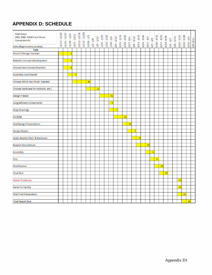
2) Use a 9/16” deep socket and a ratchet to remove the four bolts holding the lever arm shock to the cross member. Alternatively, a 9/16” socket and a short extension could be used.
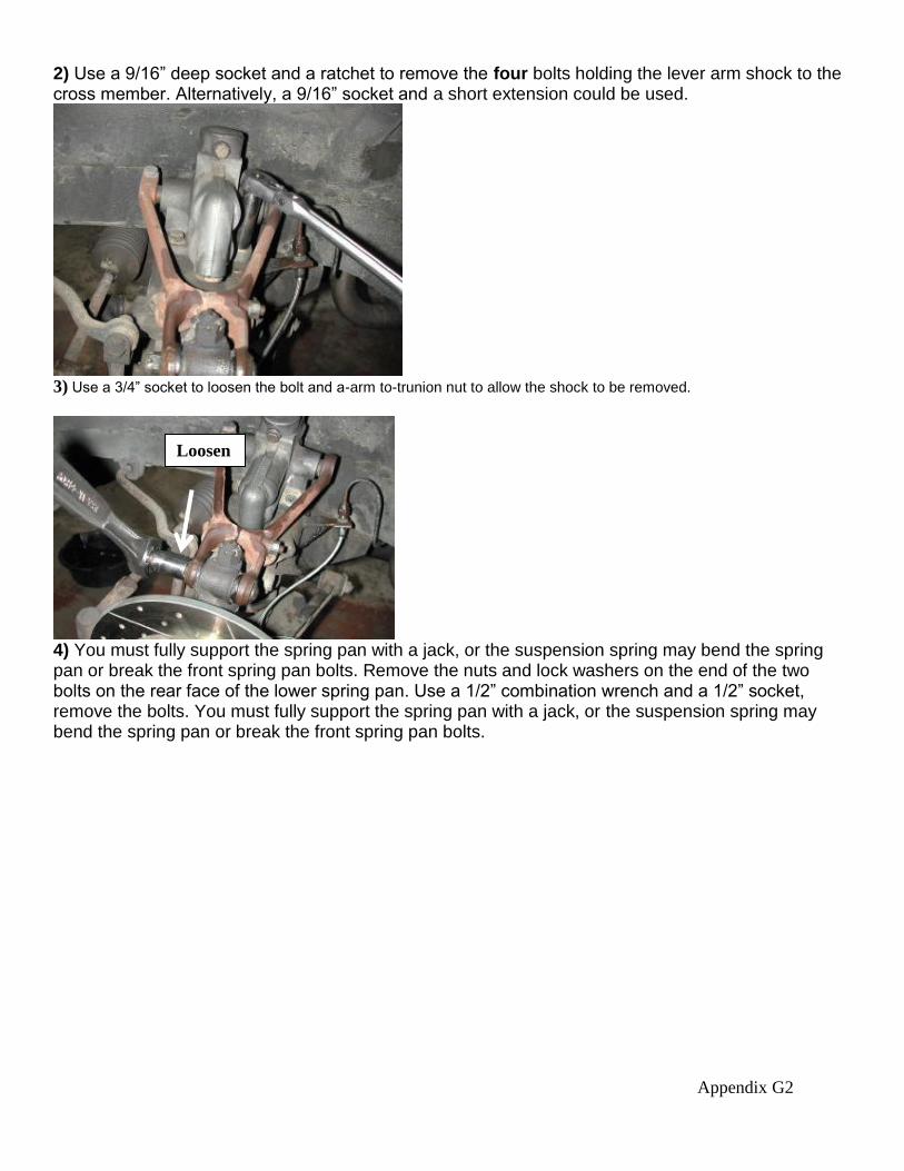
3) Use a 3/4” socket to loosen the bolt and a-arm to-trunion nut to allow the shock to be removed.
4) You must fully support the spring pan with a jack, or the suspension spring may bend the spring pan or break the front spring pan bolts. Remove the nuts and lock washers on the end of the two bolts on the rear face of the lower spring pan. Use a 1/2” combination wrench and a 1/2” socket, remove the bolts. You must fully support the spring pan with a jack, or the suspension spring may bend the spring pan or break the front spring pan bolts.
Loosen

Appendix G3
5) Slide the new lower shock bracket (the lowers are the same) over the two bolts in the lower spring pan with the shock stud parallel to the hole in the upper shock mount. Slide on the factory lock washers. Thread on the provided 5/16-24 nuts and tighten them to 18 ft.-lbs. with a 1/2” socket.
6) Slide a 1/2” washer over a provided 1/2-13 x 2.5” bolt. Slide it into the lower eye of a shock, with the “S”of SensaTrac at the top. Apply blue Loctite to the bolt and thread it into the lower bracket.
. 7) Install the top bracket swivel assembly in the same location the old shock was. Reuse the old shock bolts to mount. Be careful not to cross thread them. Torque bolts to 30 ft-lbs in a cross pattern using a 9/16 deep socket (or socket and short extension) and a ratchet

Appendix G4
8) Attach the arms of the swivel to the upper arm, torque the bolt and nut at the end of the upper A-arm to 30 ft-lbs. Note: this bolt should not be too tight, as that will restrict the movement of the arm. If there is a cotter pin, reinstall it after tightening.
9) Slide a 1/2” washer over a provided 1/2-13 x 2.5” bolt. Slide it into the upper eye of a shock Apply blue Loctite to the bolt and thread it into the nut.