Embed Size (px)
Citation preview
MC1416.102006
MAINTENANCE AND USE HANDBOOK
Equipment: MULTICONTAINER®
MCBT 14-16
CAYVOL S.C.C.L. C/ Cadaqués, 21 Polígono Industrial 08120 LA LLAGOSTA (Barcelona)
Telephone: 93 544 37 60 Fax: 93 560 36 89
e-mail: [email protected]
Maintenance and use handbook MULTICONTAINER
1
This equipment has been built by:
CAYVOL S.C.C.L. Polig. Ind. La Llagosta. C/ Cadaqués, 21
La Llagosta 08120 (Barcelona)
Telephone: ℡ 93 544 37 60 Fax: 93 560 36 89
e-mail: [email protected]
INDEX
Introduction......................................................................................... 2
Equipment parts description ..................................................................... 3
2.1- Equipment and main elements................................................................... 3
2.2- Main controls and functions ...................................................................... 4
2.3- Symbols used........................................................................................ 6
Equipment operations description .............................................................. 7
3.1- Container loading operation ..................................................................... 7
3.2- Tipping operation .................................................................................. 12
3.3- Container unloading operation .................................................................. 16
Greasing and basic maintenance of the equipment .........................................19
4.1- Greasing ............................................................................................ 19
4.2- Recommended hydraulic oil ..................................................................... 19
4.3- Greasing points ..................................................................................... 20
4.4- Oil and filter changes ............................................................................. 21
4.5- Other points to check ............................................................................. 21
Notice about the use of this equipment ....................................................... 22
Causes for bad operation ......................................................................... 23
Spare parts list .................................................................................... 25
7.1- Cylinders
7.2- Structure
7.3- Circuits
Maintenance and use handbook MULTICONTAINER
2
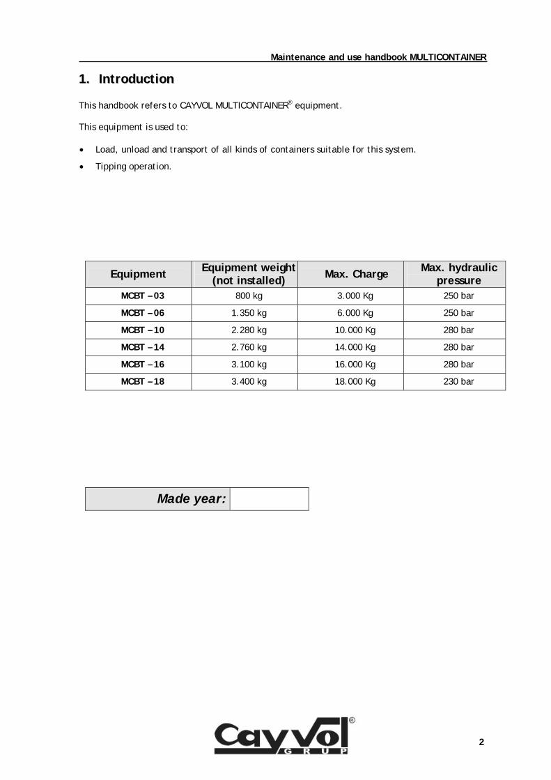
11.. IInnttrroodduuccttiioonn This handbook refers to CAYVOL MULTICONTAINER® equipment. This equipment is used to:
• Load, unload and transport of all kinds of containers suitable for this system.
• Tipping operation.
Equipment Equipment weight (not installed)
Max. Charge Max. hydraulic pressure
MCBT – 03 800 kg 3.000 Kg 250 bar
MCBT – 06 1.350 kg 6.000 Kg 250 bar
MCBT – 10 2.280 kg 10.000 Kg 280 bar
MCBT – 14 2.760 kg 14.000 Kg 280 bar
MCBT – 16 3.100 kg 16.000 Kg 280 bar
MCBT – 18 3.400 kg 18.000 Kg 230 bar
Made year:
Maintenance and use handbook MULTICONTAINER
3
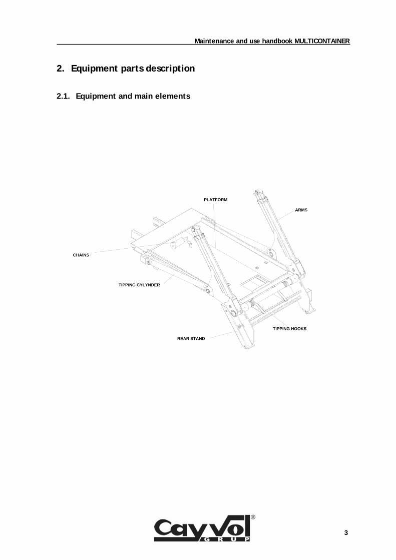
22.. EEqquuiippmmeenntt ppaarrttss ddeessccrriippttiioonn
2.1. Equipment and main elements
CHAINS
TIPPING CYLYNDER
REAR STAND
PLATFORM
TIPPING HOOKS
ARMS
Maintenance and use handbook MULTICONTAINER
4
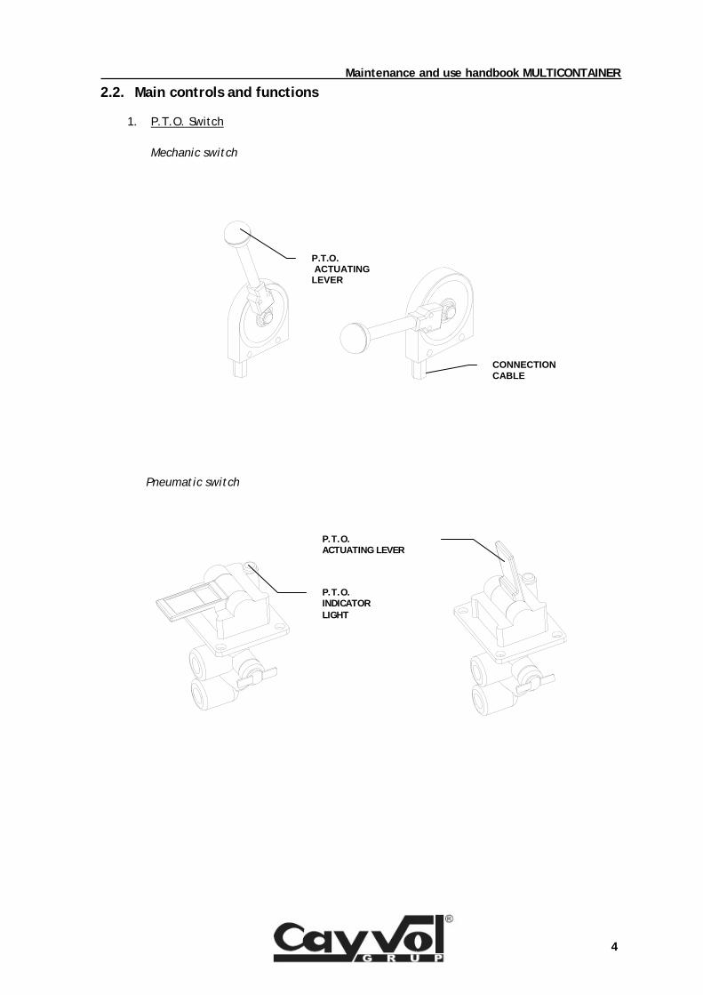
2.2. Main controls and functions
1. P.T.O. Switch
Mechanic switch Pneumatic switch
P.T.O. ACTUATING LEVER
CONNECTION CABLE
P.T.O. INDICATOR LIGHT
P.T.O. ACTUATING LEVER
Maintenance and use handbook MULTICONTAINER
5
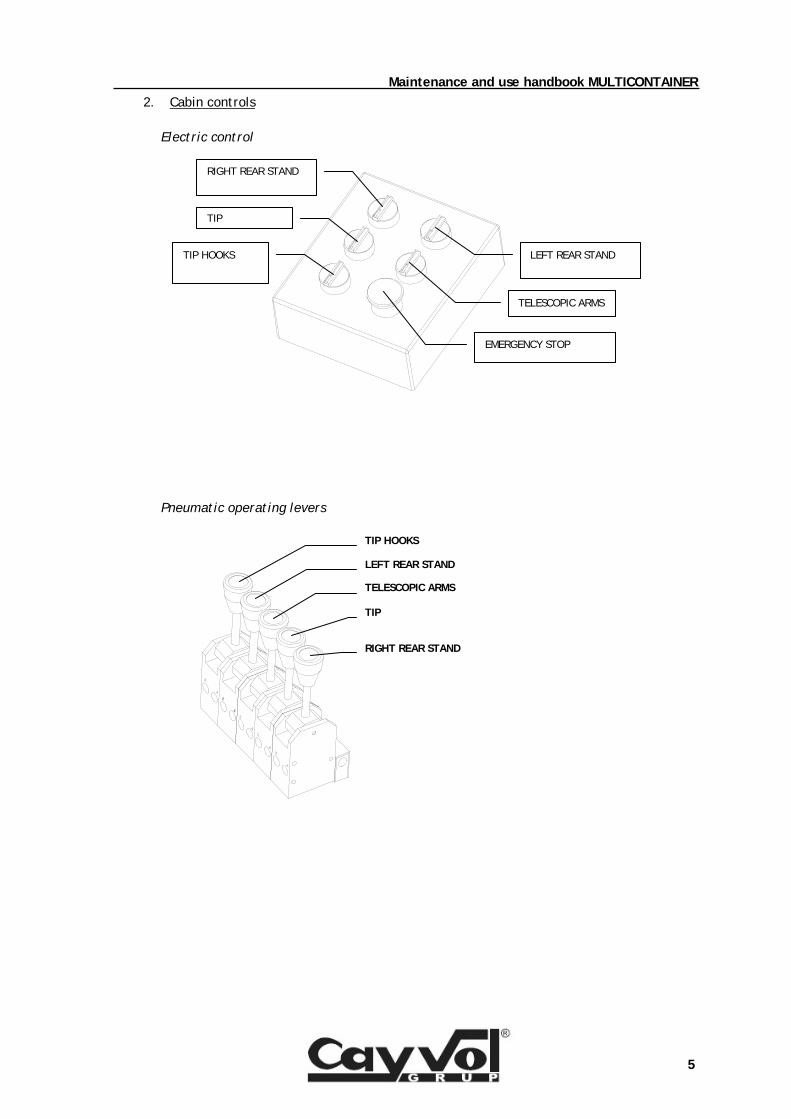
2. Cabin controls
Electric control Pneumatic operating levers
RIGHT REAR STAND
TIP
TELESCOPIC ARMS
LEFT REAR STAND
TIP HOOKS
EMERGENCY STOP
TELESCOPIC ARMS
LEFT REAR STAND
RIGHT REAR STAND
TIP
TIP HOOKS
Maintenance and use handbook MULTICONTAINER
6
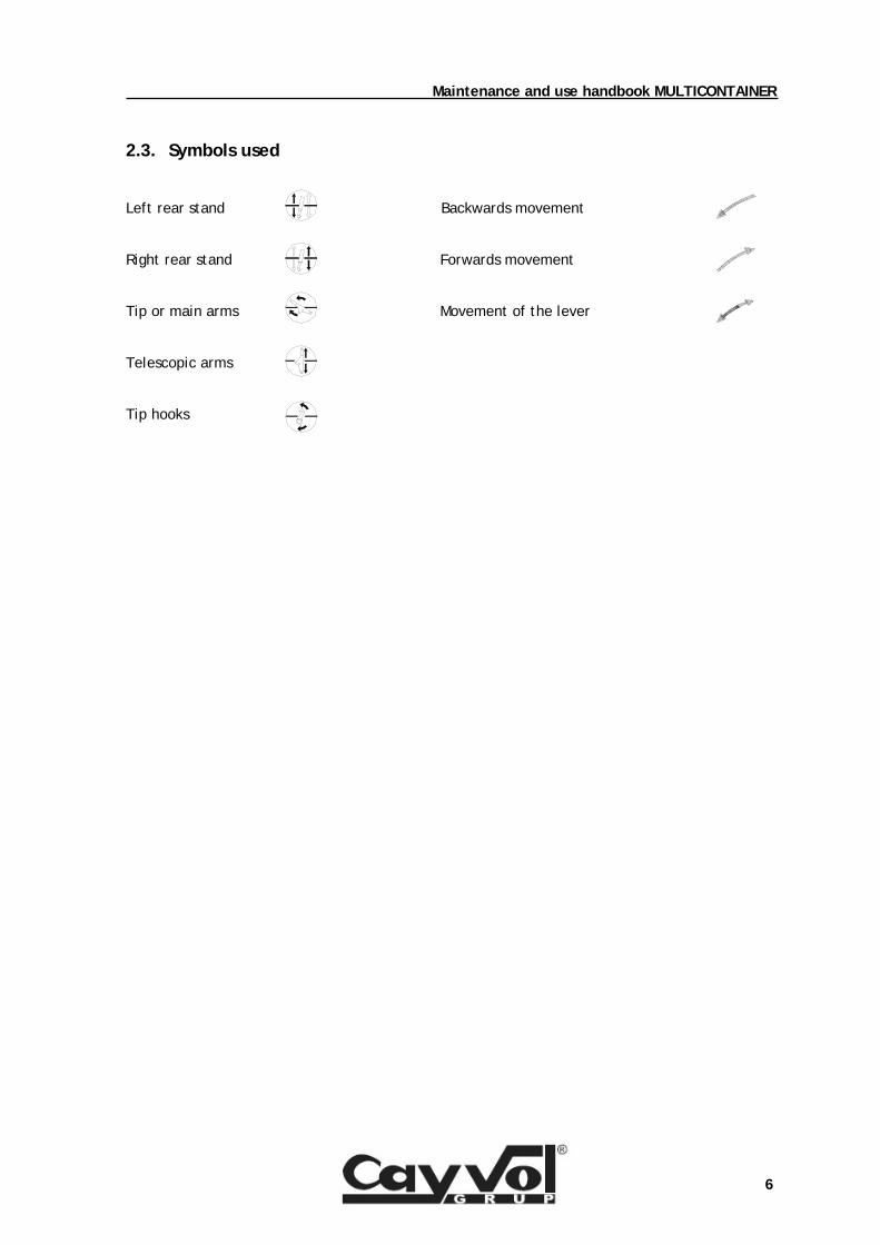
2.3. Symbols used Left rear stand Backwards movement Right rear stand Forwards movement Tip or main arms Movement of the lever Telescopic arms Tip hooks
Maintenance and use handbook MULTICONTAINER
7
P.T.O. LIGHT INDICATOR
33.. EEqquuiippmmeenntt ooppeerraattiioonnss ddeessccrriippttiioonn
IF THERE IS A DANGER SITUATION OR THE EQUIPMENT BECOMES OUT OF CONTROL, PRESS THE EMERGENCY STOP, SITUATED AT THE RIGHT SIDE OF THE EXTERNAL CONTROLS. THE EMERGENCY STOP MUST NOT BE UNLOCKED UNTIL THE EQUIPMENT HAS BEEN REPAIRED OR DANGER SITUATION DOES NO EXIST.
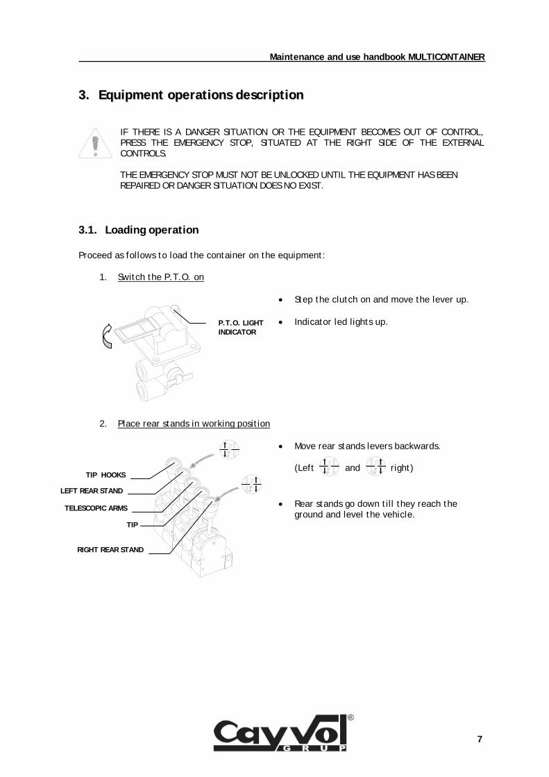
3.1. Loading operation Proceed as follows to load the container on the equipment:
1. Switch the P.T.O. on
• Step the clutch on and move the lever up.
• Indicator led lights up.
2. Place rear stands in working position
• Move rear stands levers backwards.
(Left and right)
• Rear stands go down till they reach the ground and level the vehicle.
RIGHT REAR STAND
TIP
TELESCOPIC ARMS
LEFT REAR STAND
TIP HOOKS
Maintenance and use handbook MULTICONTAINER
8
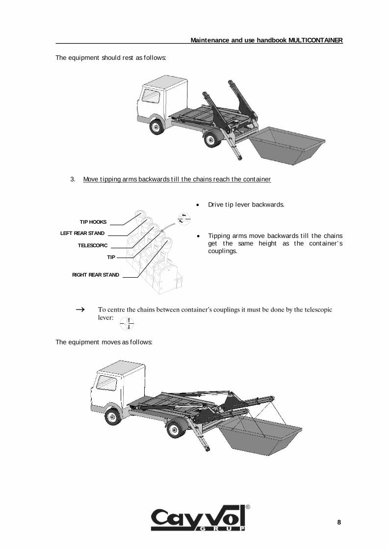
The equipment should rest as follows:
3. Move tipping arms backwards till the chains reach the container
• Drive tip lever backwards.
• Tipping arms move backwards till the chains get the same height as the container’s couplings.
→ To centre the chains between container’s couplings it must be done by the telescopic lever:
The equipment moves as follows:
RIGHT REAR STAND
TIP
TELESCOPIC
LEFT REAR STAND
TIP HOOKS
Maintenance and use handbook MULTICONTAINER
9
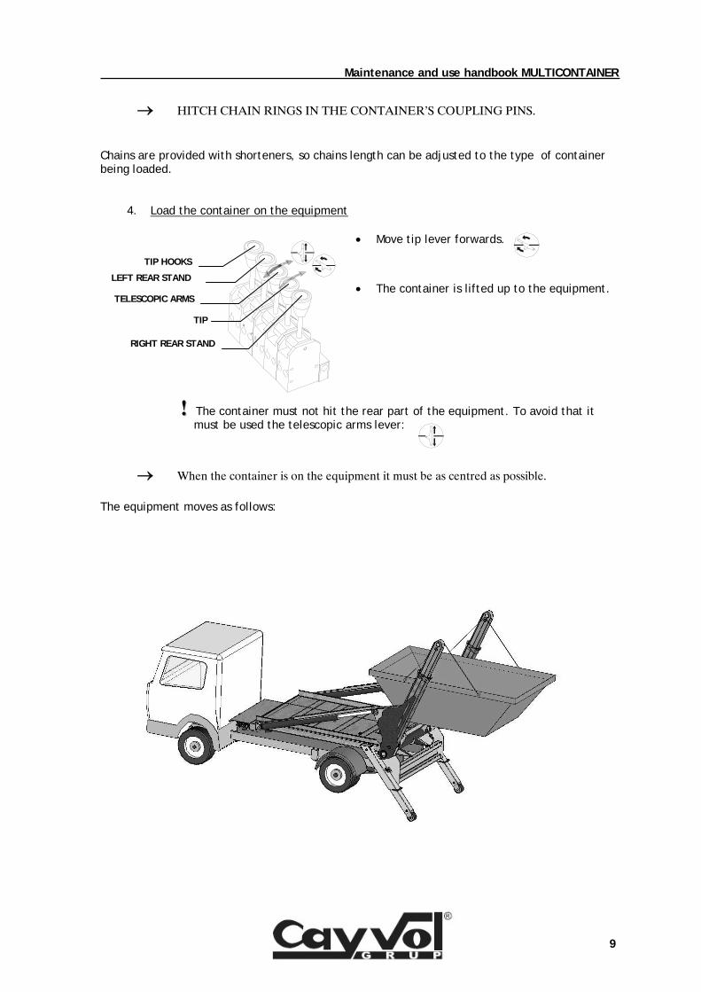
→ HITCH CHAIN RINGS IN THE CONTAINER’S COUPLING PINS. Chains are provided with shorteners, so chains length can be adjusted to the type of container being loaded.
4. Load the container on the equipment
• Move tip lever forwards.
• The container is lifted up to the equipment.
!! The container must not hit the rear part of the equipment. To avoid that it must be used the telescopic arms lever:
→ When the container is on the equipment it must be as centred as possible. The equipment moves as follows:
RIGHT REAR STAND
TIP
TELESCOPIC ARMS
LEFT REAR STAND
TIP HOOKS
Maintenance and use handbook MULTICONTAINER
10
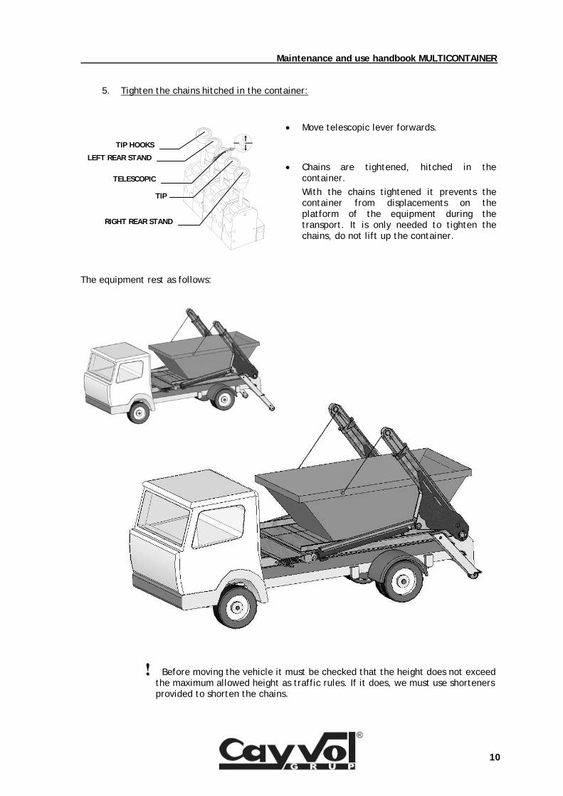
5. Tighten the chains hitched in the container:
• Move telescopic lever forwards.
• Chains are tightened, hitched in the container. With the chains tightened it prevents the container from displacements on the platform of the equipment during the transport. It is only needed to tighten the chains, do not lift up the container.
The equipment rest as follows:
!! Before moving the vehicle it must be checked that the height does not exceed the maximum allowed height as traffic rules. If it does, we must use shorteners provided to shorten the chains.
RIGHT REAR STAND
TIP
TELESCOPIC
LEFT REAR STAND
TIP HOOKS
Maintenance and use handbook MULTICONTAINER
11
P.T.O. LIGHT INDICATOR
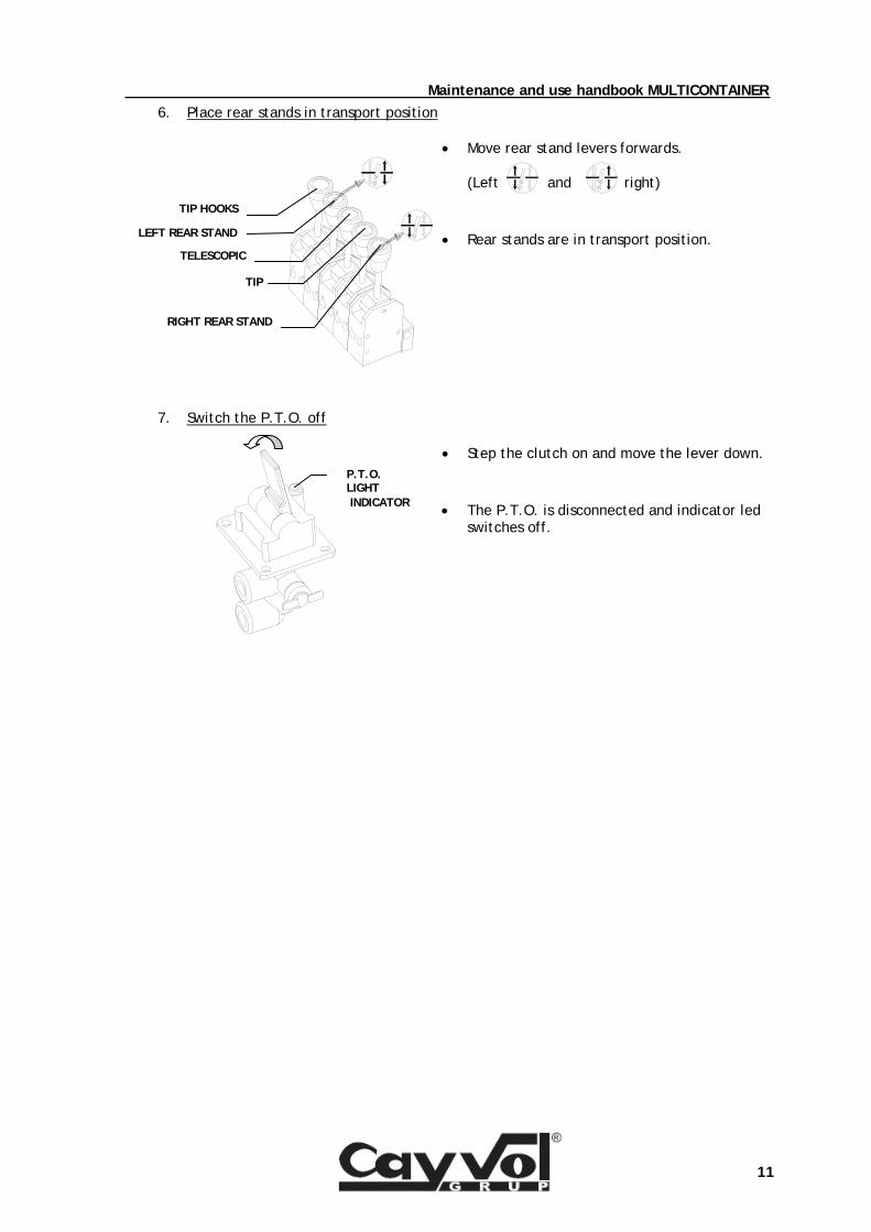
6. Place rear stands in transport position
• Move rear stand levers forwards.
(Left and right)
• Rear stands are in transport position.
7. Switch the P.T.O. off
• Step the clutch on and move the lever down.
• The P.T.O. is disconnected and indicator led switches off.
RIGHT REAR STAND
TIP
TELESCOPIC
LEFT REAR STAND
TIP HOOKS
Maintenance and use handbook MULTICONTAINER
12
P.T.O. LIGHT INDICATOR
3.2. Tipping operation Place the vehicle when we want to pour the container’s contents out.
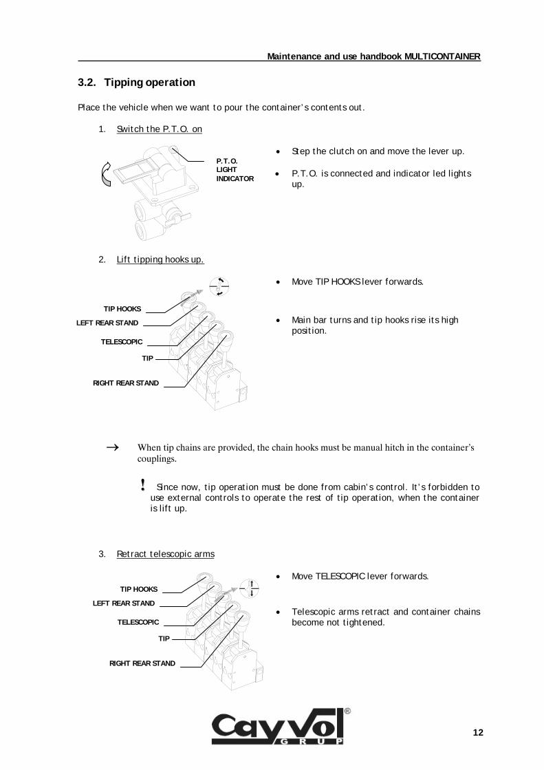
1. Switch the P.T.O. on
• Step the clutch on and move the lever up.
• P.T.O. is connected and indicator led lights up.
2. Lift tipping hooks up.
• Move TIP HOOKS lever forwards.
• Main bar turns and tip hooks rise its high position.
→ When tip chains are provided, the chain hooks must be manual hitch in the container’s couplings.
!! Since now, tip operation must be done from cabin’s control. It’s forbidden to use external controls to operate the rest of tip operation, when the container is lift up.
3. Retract telescopic arms
• Move TELESCOPIC lever forwards.
• Telescopic arms retract and container chains become not tightened.
RIGHT REAR STAND
TIP
TELESCOPIC
LEFT REAR STAND
TIP HOOKS
RIGHT REAR STAND
TIP
TELESCOPIC
LEFT REAR STAND
TIP HOOKS
Maintenance and use handbook MULTICONTAINER
13
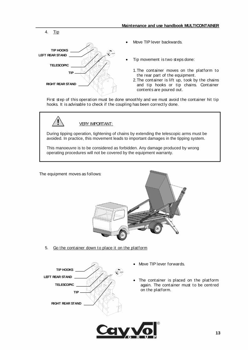
4. Tip
• Move TIP lever backwards.
• Tip movement is two steps done: 1. The container moves on the platform to
the rear part of the equipment. 2. The container is lift up, took by the chains
and tip hooks or tip chains. Container contents are poured out.
First step of this operation must be done smoothly and we must avoid the container hit tip hooks. It is advisable to check if the coupling has been correctly done.
The equipment moves as follows:
5. Go the container down to place it on the platform
• Move TIP lever forwards.
• The container is placed on the platform again. The container must to be centred on the platform.
VERY IMPORTANT: During tipping operation, tightening of chains by extending the telescopic arms must be avoided. In practice, this movement leads to important damages in the tipping system. This manoeuvre is to be considered as forbidden. Any damage produced by wrong operating procedures will not be covered by the equipment warranty.
RIGHT REAR STAND
TIP
TELESCOPIC
LEFT REAR STANDTIP HOOKS
RIGHT REAR STAND
TIP
TELESCOPIC
LEFT REAR STAND
TIP HOOKS
Maintenance and use handbook MULTICONTAINER
14
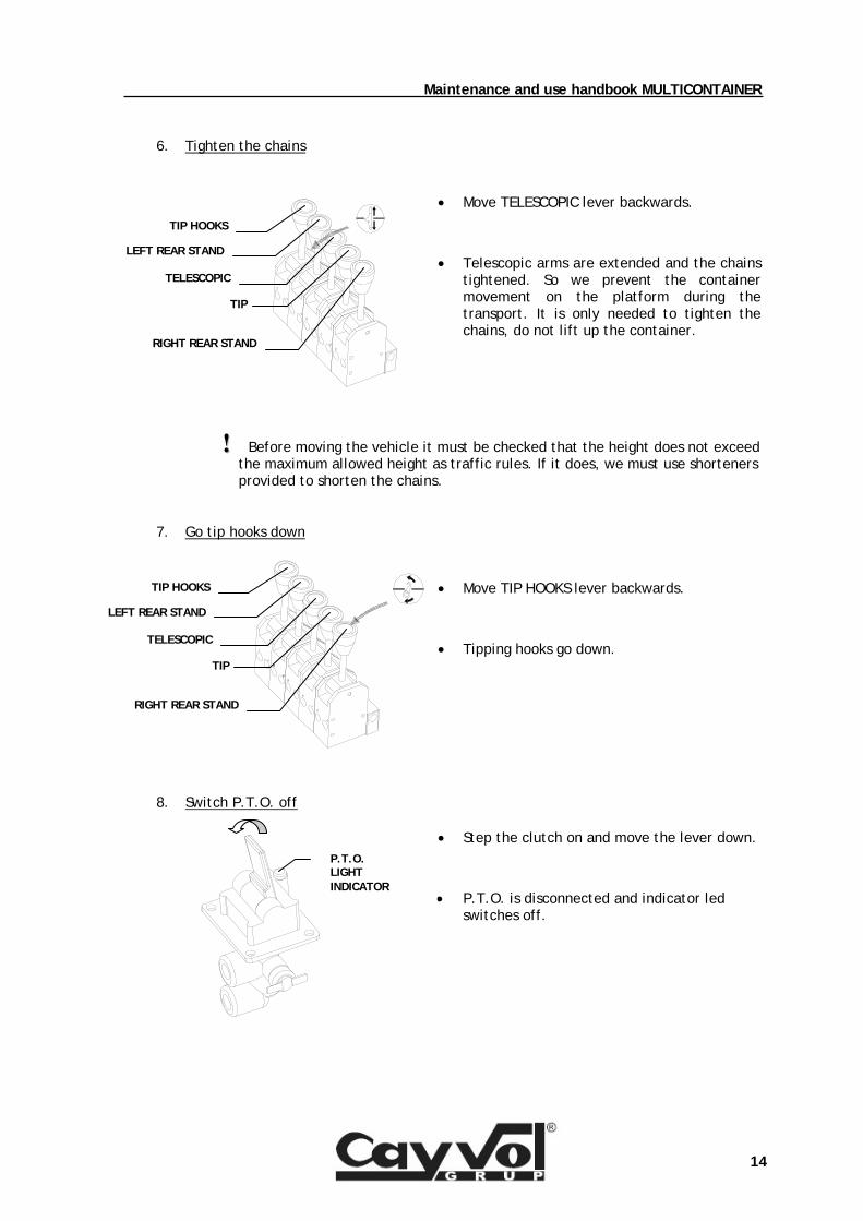
6. Tighten the chains
• Move TELESCOPIC lever backwards.
• Telescopic arms are extended and the chains tightened. So we prevent the container movement on the platform during the transport. It is only needed to tighten the chains, do not lift up the container.
!! Before moving the vehicle it must be checked that the height does not exceed the maximum allowed height as traffic rules. If it does, we must use shorteners provided to shorten the chains.
7. Go tip hooks down
• Move TIP HOOKS lever backwards.
• Tipping hooks go down.
8. Switch P.T.O. off
• Step the clutch on and move the lever down.
• P.T.O. is disconnected and indicator led switches off.
RIGHT REAR STAND
TIP
TELESCOPIC
LEFT REAR STAND
TIP HOOKS
RIGHT REAR STAND
TIP
TELESCOPIC
LEFT REAR STAND
TIP HOOKS
P.T.O. LIGHT INDICATOR
Maintenance and use handbook MULTICONTAINER
15
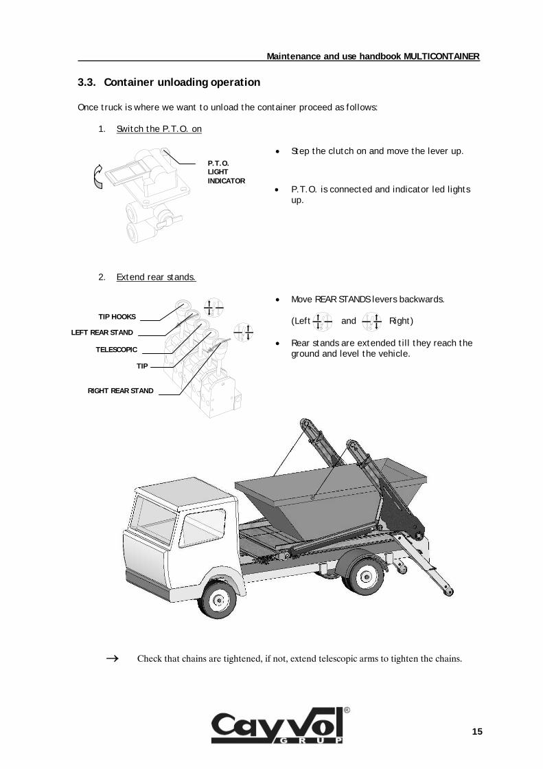
3.3. Container unloading operation Once truck is where we want to unload the container proceed as follows:
1. Switch the P.T.O. on
• Step the clutch on and move the lever up.
• P.T.O. is connected and indicator led lights up.
2. Extend rear stands.
• Move REAR STANDS levers backwards.
(Left and Right)
• Rear stands are extended till they reach the ground and level the vehicle.
→ Check that chains are tightened, if not, extend telescopic arms to tighten the chains.
P.T.O. LIGHT INDICATOR
RIGHT REAR STAND
TIP
TELESCOPIC
LEFT REAR STAND
TIP HOOKS
Maintenance and use handbook MULTICONTAINER
16
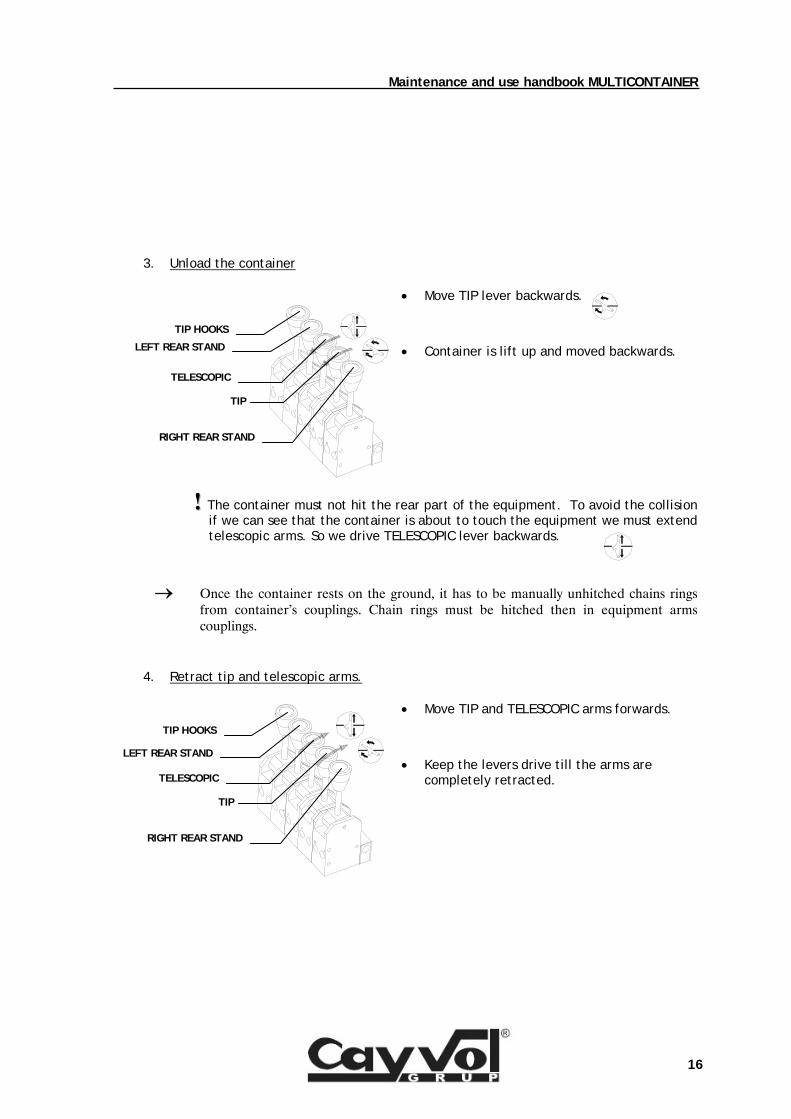
3. Unload the container
• Move TIP lever backwards.
• Container is lift up and moved backwards.
!! The container must not hit the rear part of the equipment. To avoid the collision if we can see that the container is about to touch the equipment we must extend telescopic arms. So we drive TELESCOPIC lever backwards.
→ Once the container rests on the ground, it has to be manually unhitched chains rings from container’s couplings. Chain rings must be hitched then in equipment arms couplings.
4. Retract tip and telescopic arms.
• Move TIP and TELESCOPIC arms forwards.
• Keep the levers drive till the arms are completely retracted.
RIGHT REAR STAND
TIP
TELESCOPIC
LEFT REAR STAND
TIP HOOKS
RIGHT REAR STAND
TIP
TELESCOPIC
LEFT REAR STAND
TIP HOOKS
Maintenance and use handbook MULTICONTAINER
17
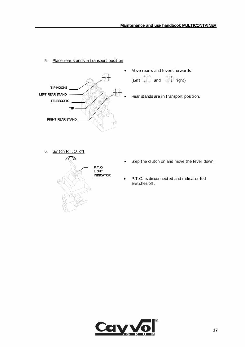
5. Place rear stands in transport position
• Move rear stand levers forwards.
(Left and right)
• Rear stands are in transport position.
6. Switch P.T.O. off
• Step the clutch on and move the lever down.
• P.T.O. is disconnected and indicator led switches off.
RIGHT REAR STAND
TIP
TELESCOPIC
LEFT REAR STAND
TIP HOOKS
P.T.O. LIGHT INDICATOR
Maintenance and use handbook MULTICONTAINER
18
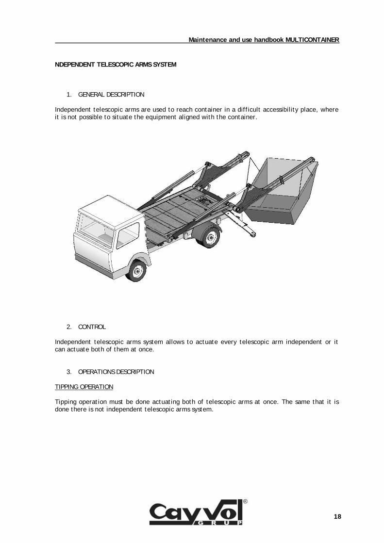
NDEPENDENT TELESCOPIC ARMS SYSTEM
1. GENERAL DESCRIPTION Independent telescopic arms are used to reach container in a difficult accessibility place, where it is not possible to situate the equipment aligned with the container.
2. CONTROL Independent telescopic arms system allows to actuate every telescopic arm independent or it can actuate both of them at once.
3. OPERATIONS DESCRIPTION TIPPING OPERATION Tipping operation must be done actuating both of telescopic arms at once. The same that it is done there is not independent telescopic arms system.
Maintenance and use handbook MULTICONTAINER
19
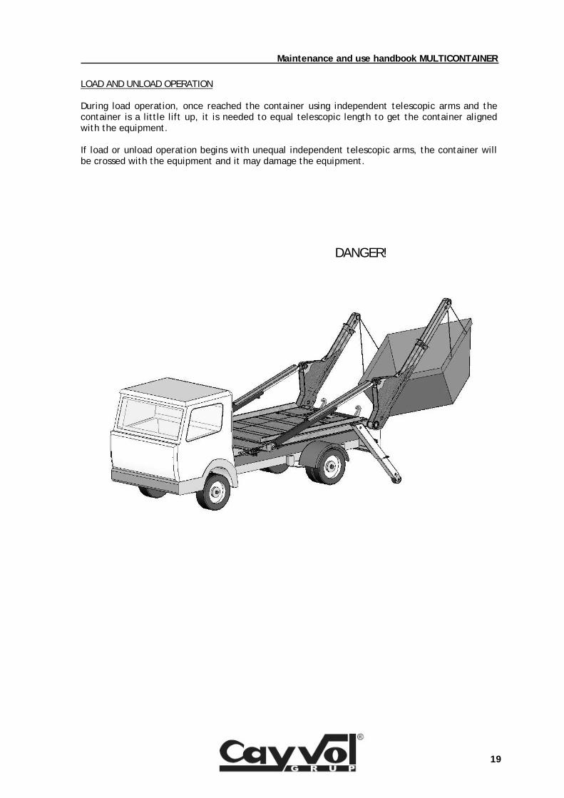
LOAD AND UNLOAD OPERATION During load operation, once reached the container using independent telescopic arms and the container is a little lift up, it is needed to equal telescopic length to get the container aligned with the equipment. If load or unload operation begins with unequal independent telescopic arms, the container will be crossed with the equipment and it may damage the equipment.
DANGER!
Maintenance and use handbook MULTICONTAINER
20
44.. GGRREEAASSIINNGG AANNDD BBAASSIICC MMAAIINNTTEENNAANNCCEE OOFF TTHHEE EEQQUUIIPPMMEENNTT..
4.1. Greasing.
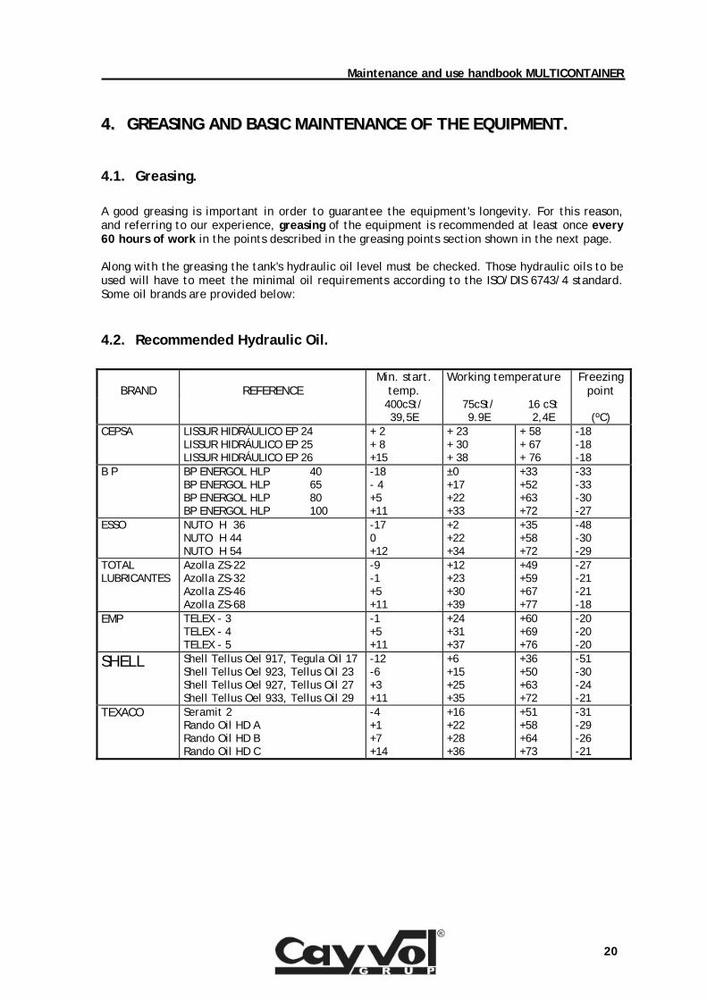
A good greasing is important in order to guarantee the equipment's longevity. For this reason, and referring to our experience, greasing of the equipment is recommended at least once every 60 hours of work in the points described in the greasing points section shown in the next page. Along with the greasing the tank's hydraulic oil level must be checked. Those hydraulic oils to be used will have to meet the minimal oil requirements according to the ISO/DIS 6743/4 standard. Some oil brands are provided below:
4.2. Recommended Hydraulic Oil.
BRAND
REFERENCE
Min. start. temp.
Working temperature Freezing point
400cSt/ 39,5E
75cSt/ 9.9E
16 cSt 2,4E
(ºC)
CEPSA LISSUR HIDRÁULICO EP 24 LISSUR HIDRÁULICO EP 25 LISSUR HIDRÁULICO EP 26
+ 2 + 8 +15
+ 23 + 30 + 38
+ 58 + 67 + 76
-18 -18 -18
B P BP ENERGOL HLP 40 BP ENERGOL HLP 65 BP ENERGOL HLP 80 BP ENERGOL HLP 100
-18 - 4 +5 +11
±0 +17 +22 +33
+33 +52 +63 +72
-33 -33 -30 -27
ESSO NUTO H 36 NUTO H 44 NUTO H 54
-17 0 +12
+2 +22 +34
+35 +58 +72
-48 -30 -29
TOTAL LUBRICANTES
Azolla ZS-22 Azolla ZS-32 Azolla ZS-46 Azolla ZS-68
-9 -1 +5 +11
+12 +23 +30 +39
+49 +59 +67 +77
-27 -21 -21 -18
EMP TELEX - 3 TELEX - 4 TELEX - 5
-1 +5 +11
+24 +31 +37
+60 +69 +76
-20 -20 -20
SHELL Shell Tellus Oel 917, Tegula Oil 17 Shell Tellus Oel 923, Tellus Oil 23 Shell Tellus Oel 927, Tellus Oil 27 Shell Tellus Oel 933, Tellus Oil 29
-12 -6 +3 +11
+6 +15 +25 +35
+36 +50 +63 +72
-51 -30 -24 -21
TEXACO Seramit 2 Rando Oil HD A Rando Oil HD B Rando Oil HD C
-4 +1 +7 +14
+16 +22 +28 +36
+51 +58 +64 +73
-31 -29 -26 -21
Maintenance and use handbook MULTICONTAINER
21
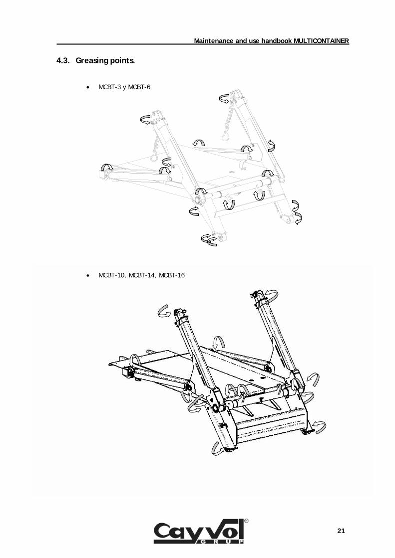
4.3. Greasing points.
• MCBT-3 y MCBT-6
• MCBT-10, MCBT-14, MCBT-16
Maintenance and use handbook MULTICONTAINER
22
4.4. Oil and filter changes.
First time to change the filter must be after 50 hours of operation. It is recommended to change both the oil and the filter every 300 hours of operation, depending on the system dirt. Tank must be emptied at normal operation temperature. The hydraulic circuit pump should not be used to perform emptying. This operation must be done by means of the cap at the tank's bottom. Every time that we change the hydraulic oil the tank and the circuit must be cleaned. It is advisable to replace the return filter cartridge too, and every time after each repair work or inspection. When the equipment works in a very polluted environment, the pumps' tightness can become damaged and lead to oil leaks and, consequently, to a loss in efficiency. New or repaired components must not be assembled onto the hydraulic system until it has been cleaned. Dirt must be prevented as much as possible by using humid air filters if necessary. The oil level must be periodically checked. An excessive consumption must be analysed and avoided. Leaks in pipe joints and oil seals must be eliminated when the system is not operating. Afterwards we must proceed to fill the tank. Hydraulic oil used must be ISO/DIS 6743/4 grade. At working temperature oil viscosity must be between 10 and 30 cSt (from 3 to 4 E). Oil’s maximum working temperature in continuous work must not exceed 75 ºC.
4.5. Other points to check. It must be periodically checked (it's recommended to do so each time the equipment is greased): • The right securing of the fixing screws and particularly those which hold the false chassis
to truck chassis. • The dump hooks and the chains, looking for likely faults or cracks that may have been caused
by its use.
55.. NNOOTTIICCEE AABBOOUUTT TTHHEE UUSSEE OOFF TTHHIISS EEQQUUIIPPMMEENNTT
Maintenance and use handbook MULTICONTAINER
23
- It is absolutely forbidden to circulate with the P.T.O. switched on (P.T.O. indicator on). That could lead to mechanical damage both in the gearbox and the hydraulic system, with the further possibility that the equipment might set into operation by itself and the consequences this could entail. - It is strictly forbidden to perform any kind of maintenance operation on the equipment while the vehicle's engine is working. - It is completely forbidden to perform the swing operation from the distributor's external controls. Besides, and due to the fact that this operation is so extremely dangerous in itself, the worker will make sure that both ground and charge conditions are fine to avoid the vehicle's overturn. - It is forbidden to carry out lifting and deposing operations of the container both/either without having extended the rear stands and/or with the vehicle not braked. - While operating with the equipment the worker will make sure that nobody remains inside the equipment's danger area. - Excessive increase of the vehicle's engine's turning rate during the operations not only does not increase the equipment's speed, but it can also bring about significant breakdowns in the hydraulic system. - Before driving the truck it is advisable to make sure that the rear stands are completely folded up.
Maintenance and use handbook MULTICONTAINER
24
66.. CCAAUUSSEESS FFOORR BBAADD OOPPEERRAATTIIOONN * The P.T.O. does not gear in. - Leak in pneumatic circuit. - Insufficient air pressure in the circuit. * The equipment does not perform any of its functions. - The P.T.O. is not geared in. - There is no oil in the tank. - Breakdown in the hydraulic pump. * The equipment stops before reaching the end of stroke. - Insufficient oil level in the tank. - Insufficient pressure in the vehicle's air circuit. * Cylinders do not stay in their due position after having driven the corresponding control switches. - Likely wear of cylinders' joints. - Leaks in brake valves. * The telescopic plumes become unbalanced. - Breakdown in flow divider. - Leak in one of the telescopic plume's cylinders. * The equipment performs operations very slowly and intermittently. - Tank's filter clogged. - Use of inappropriate viscosity oil. - Breakdown in pump. * Cylinders expand slightly without driving the control. - Cylinder's joints worn out.

Maintenance and use handbook MULTICONTAINER
25
SPARE LIST
90000022
D
E
F
C
1 2 3 4
B
A
321 5
C
D
4 6 7 8
A
B
Sustituido por:Sustituye a:
2003-10-15Fecha Nombre
DibujadoComprobado
M.V.C.J.B.S.2003-10-17
Código Revisión Fecha revisión420008070
5
E
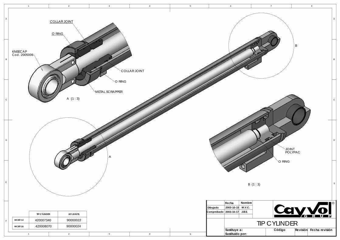
MCBT-14
MCBT-16
TIP CYLINDER KIT JOINTS
90000024
420007340TIP CYLINDER
POLYPACJOINT
B (1 : 3)
O RINGA
B
A (1 : 3)
Cod. 2005006
COLLAR JOINT
O RING
KNEECAP
O RING
COLLAR JOINT
METAL SCRAPPER
2002-04-02 Código420016080 1
Revisión Fecha revisión2004-12-095
D
E
F
C
1 2 3 4
B
A
321 5
C
D
4 6 7 8
A
B
Sustituido por:Sustituye a:
2004-12-09
Fecha Nombre
Dibujado
Comprobado
M.V.C.
J.B.S.
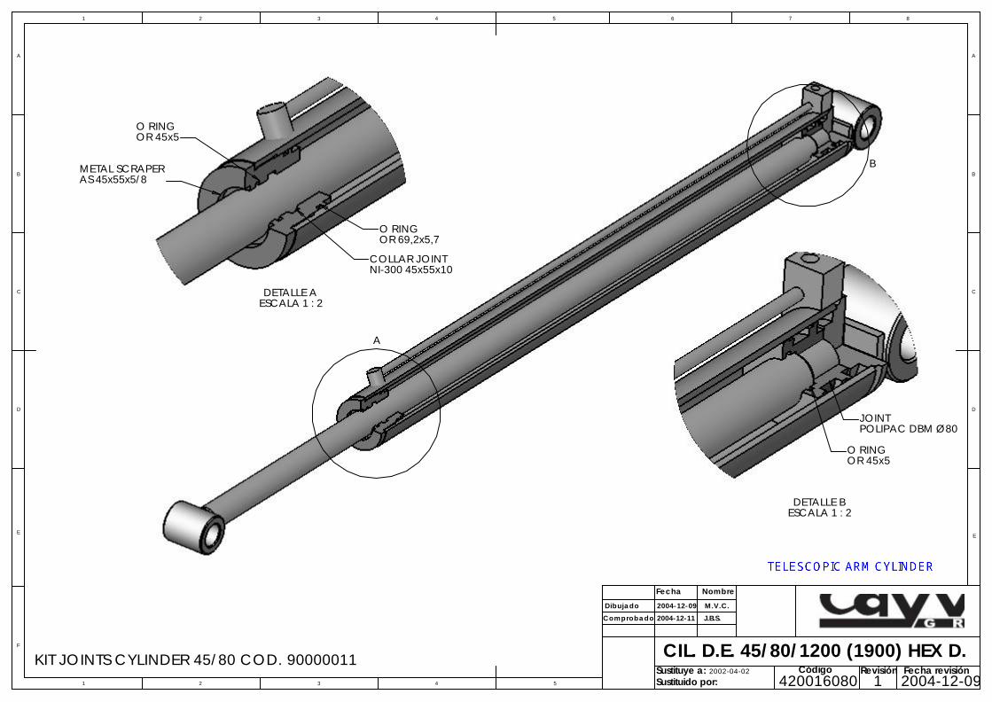
CIL. D.E. 45/80/1200 (1900) HEX D.
2004-12-11Sociedad Cooperativa Catalana Limitada
E
DETALLE B ESCALA 1 : 2
JOINTPOLIPAC DBM Ø80
O RINGOR 45x5
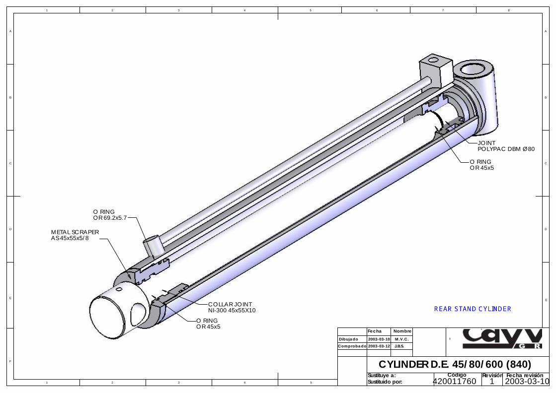
KIT JOINTS CYLINDER 45/80 COD. 90000011
DETALLE A ESCALA 1 : 2
METAL SCRAPERAS 45x55x5/8
O RINGOR 69,2x5,7
O RINGOR 45x5
COLLAR JOINTNI-300 45x55x10
A
B
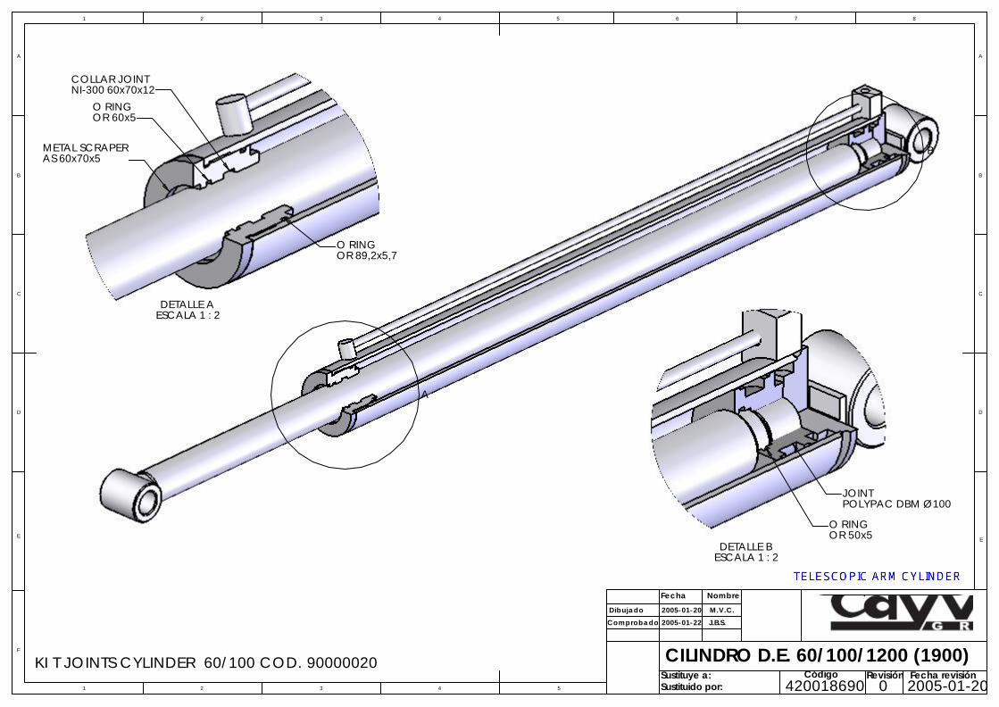
KI T JOINTS CYLINDER 60/100 COD. 90000020
DETALLE A ESCALA 1 : 2
O RINGOR 60x5
COLLAR JOINTNI-300 60x70x12
O RINGOR 89,2x5,7
METAL SCRAPERAS 60x70x5
A
B
Código420018690 0
Revisión Fecha revisión2005-01-205
D
E
F
C
1 2 3 4
B
A
321 5
C
D
4 6 7 8
A
B
Sustituido por:Sustituye a:
2005-01-20
Fecha Nombre
Dibujado
Comprobado
M.V.C.
J.B.S.
CILINDRO D.E. 60/100/1200 (1900)
2005-01-22Sociedad Cooperativa Catalana Limitada
E
DETALLE B ESCALA 1 : 2
JOINTPOLYPAC DBM Ø100
O RINGOR 50x5
COLLAR JOINTNI-300 45x55X10
POLYPAC DBM Ø80JOINT
OR 45x5O RING
OR 45x5O RING
OR 69.2x5.7O RING
METAL SCRAPERAS 45x55x5/8
5
D
E
F
C
1 2 3 4
B
A
321 5
C
D
4 6 7 8
A
B
Sustituido por:Sustituye a:
2003-03-10
Fecha Nombre
Dibujado
Comprobado
M.V.C.
J.B.S.
CYLINDER D.E. 45/80/600 (840)
2003-03-12Sociedad Cooperativa Catalana Limitada
Código420011760 1
Revisión Fecha revisión2003-03-10
E
5
D
E
F
C
1 2 3 4
B
A
321 5
C
D
4 6 7 8
A
B
Sustituido por:Sustituye a:
2003-03-10
Fecha Nombre
Dibujado
Comprobado
M.V.C.
J.B.S.
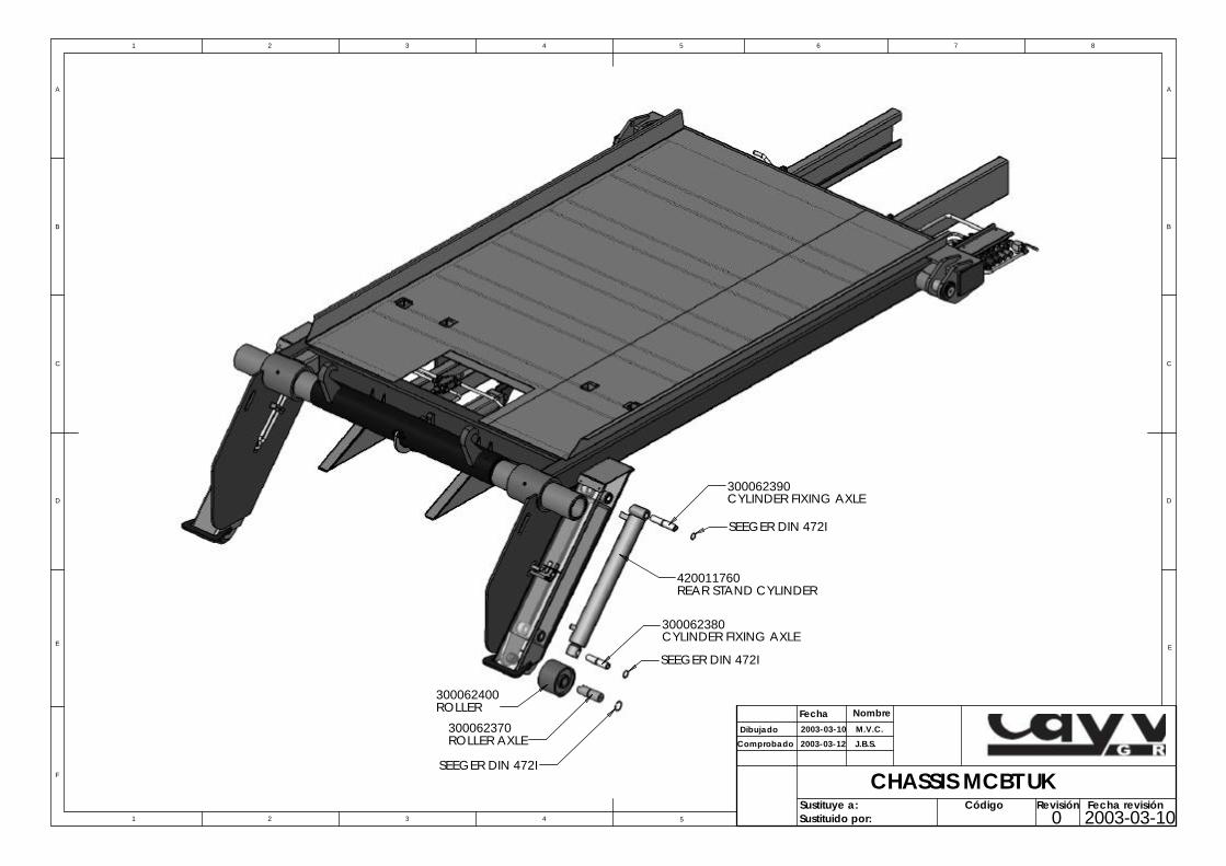
CHASSIS MCBT UK
2003-03-12Sociedad Cooperativa Catalana Limitada
Código 0
Revisión Fecha revisión2003-03-10
E
CYLINDER FIXING AXLE
SEEGER DIN 472I
CYLINDER FIXING AXLE
SEEGER DIN 472I
300062390
420011760REAR STAND CYLINDER
ROLLER AXLE
300062380
300062370
SEEGER DIN 472I
300062400 ROLLER
DETAIL B
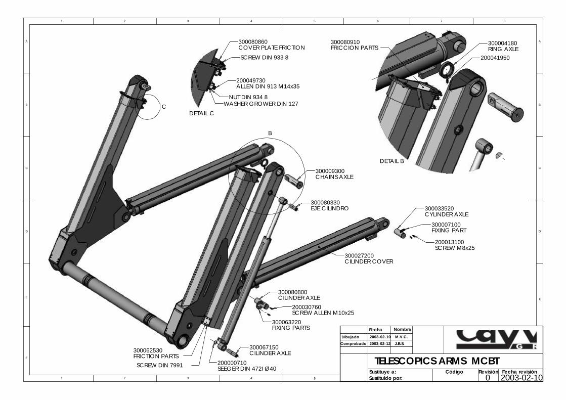
300080910FRICCION PARTS
200041950
300004180RING AXLE
NUT DIN 934 8
DETAIL C
ALLEN DIN 913 M14x35
WASHER GROWER DIN 127
200049730
SCREW DIN 933 8
300080860COVER PLATE FRICTION
2003-02-105
D
E
F
C
1 2 3 4
B
A
321 5
C
D
4 6 7 8
A
B
Sustituido por:Sustituye a:
2003-02-10
Fecha Nombre
Dibujado
Comprobado
M.V.C.
J.B.S.
TELESCOPICS ARMS MCBT
2003-02-12Sociedad Cooperativa Catalana Limitada
Código 0
Revisión Fecha revisión
E
B
C
300009300CHAINS AXLE
SCREW DIN 7991
300062530FRICTION PARTS
300067150CILINDER AXLE
200030760SCREW ALLEN M10x25
200000710SEEGER DIN 472I Ø40
300063220FIXING PARTS
300080800CILINDER AXLE
200013100SCREW M8x25
300033520CYLINDER AXLE
300007100FIXING PART
300027200CILINDER COVER
300080330EJE CILINDRO
Revisión
D
E
F
C
1 2 3 4
B
A
321 5
C
D
4 6 7 8
A
B
Sustituido por:Sustituye a:
Fecha NombreDibujado
Comprobado
1:20Escala:
1mm
Código
Tole
ranc
ias
gene
rale
sde
la p
ieza
Fecha revisión
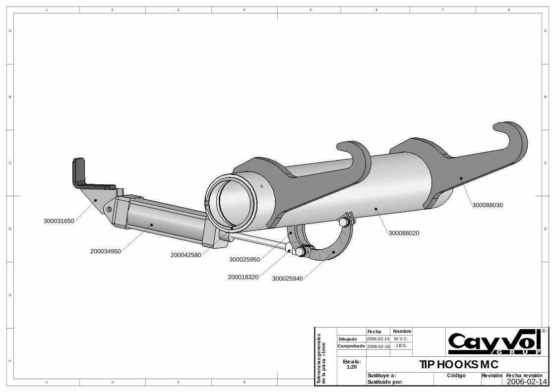
200018320
200034950
300031650
300025950
300025940
300088020
TIP HOOKS MC
M.V.C.2006-02-14
300088030
200042580
2006-02-16 J.B.S.
2006-02-14
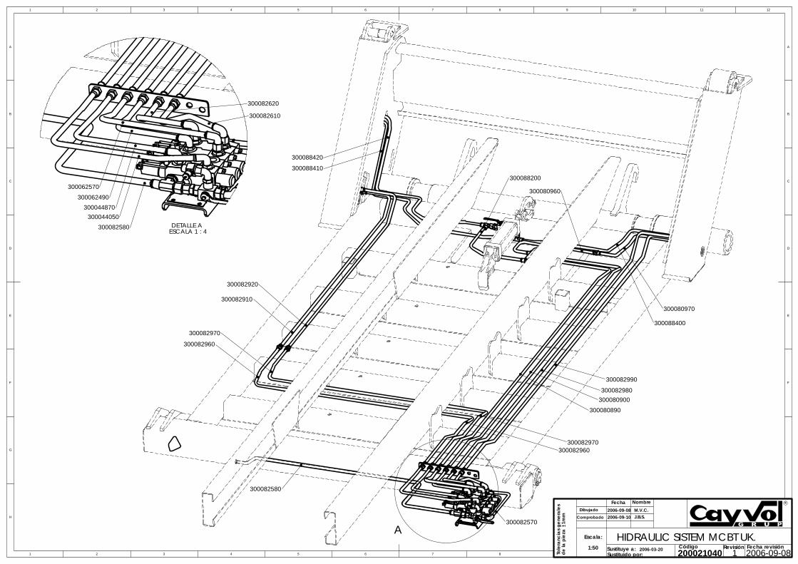
300062570
300082610
DETALLE A ESCALA 1 : 4
300082580
300044050
300044870
300062490
300082620
2006-03-20
6
D
C
B
A
E
F
G
H
E
A
B
C
D
F
54321 7 8 9 10 11 12
1 2 3 4 5 6 7 8Sustituye a:Sustituido por: 200021040
HIDRAULIC SISTEM MCBT UK.1
1:50
Comprobado
DibujadoFecha Nombre
J.B.S.
Escala:
Fecha revisión2006-09-08
1mm
2006-09-082006-09-10
Código Revisión
Tole
ranc
ias
gene
rale
sde
la p
ieza
M.V.C.
300082910
300082920
300088410
300088420
300082960
300082970
300082580
300082570
300082990
300082980300080900
300080890
300082970300082960
300088400
300080970
300080960
300088200
A
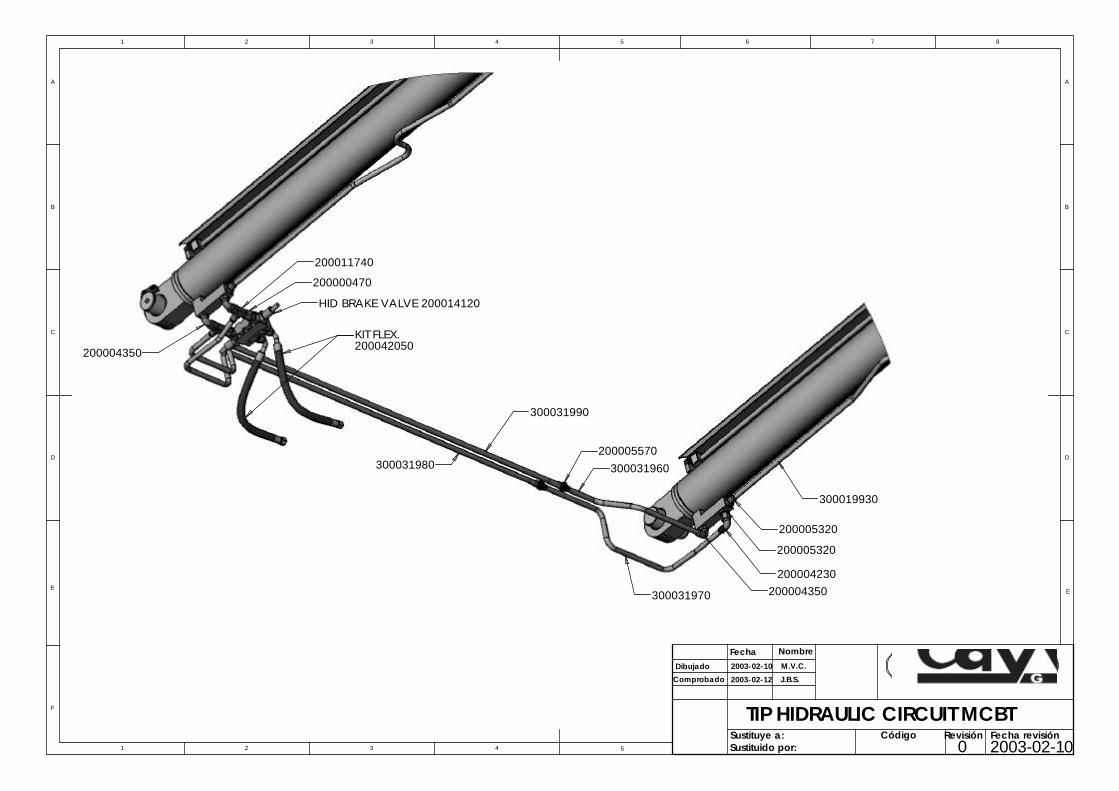
HID BRAKE VALVE 200014120
200004350300031970
300031980 300031960
300019930
200005320
200004230
200005320
300031990
200011740
200042050200004350
200000470
KIT FLEX.
200005570
5
D
E
F
C
1 2 3 4
B
A
321 5
C
D
4 6 7 8
A
B
Sustituido por:Sustituye a:
2003-02-10
Fecha Nombre
Dibujado
Comprobado
M.V.C.
J.B.S.
TIP HIDRAULIC CIRCUIT MC
2003-02-12Sociedad Cooperativa Cata
Código 0
Revisión F2
E
BT
lana Limitada
echa revisión003-02-10
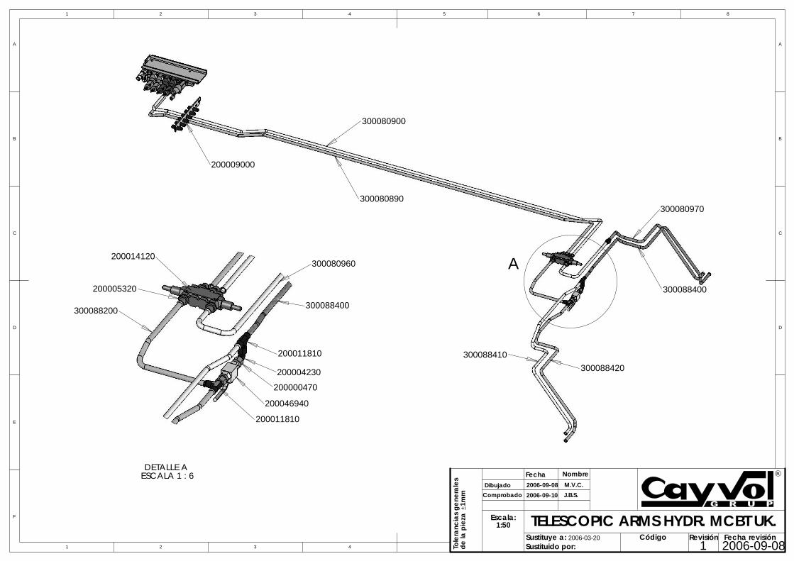
200000470
ESCALA 1 : 6DETALLE A
200014120
200005320
300088200
300080960
300088400
200011810
200004230
200046940
200011810
D
E
F
C
1 2 3 4
B
A
321 5
C
D
4 6 7 8
A
B
Sustituido por:Sustituye a:
2006-09-08Fecha Nombre
DibujadoComprobado
M.V.C.J.B.S.
Escala:1:50
Tole
ranc
ias
gene
rale
sde
la p
ieza
1m
m
TELESCOPIC ARMS HYDR. MCBT UK.
2006-09-10
2006-03-20 Código 1
Revisión Fecha revisión2006-09-08
300080900
300080890
200009000
300080970
300088400
300088420300088410
A
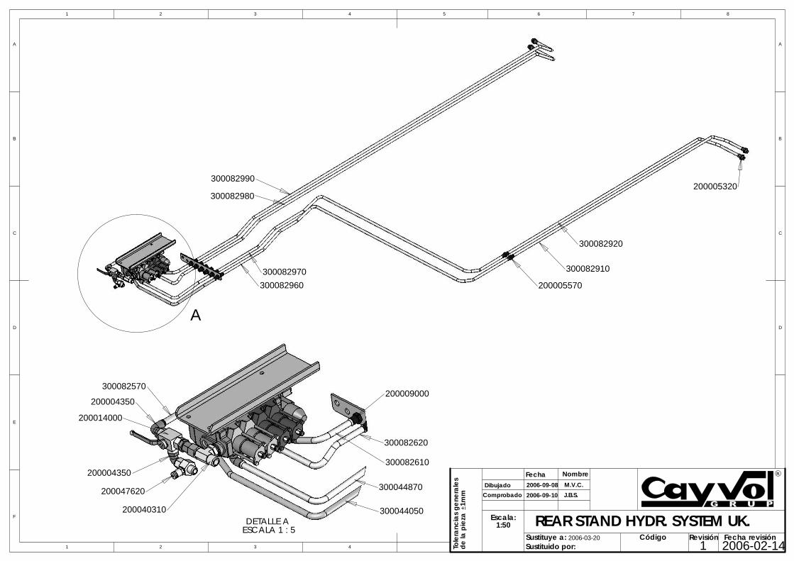
200047620
ESCALA 1 : 5DETALLE A
300082620
300082610
300044870
300044050
200009000300082570
200004350
200014000
200004350
200040310
300082960
300082970
300082990
300082980
300082910
300082920
200005570
200005320
AD
E
F
C
1 2 3 4
B
A
321 5
C
D
4 6 7 8
A
B
Sustituido por:Sustituye a:
2006-09-08Fecha Nombre
DibujadoComprobado
M.V.C.J.B.S.
Escala:1:50
Tole
ranc
ias
gene
rale
sde
la p
ieza
1m
m
REAR STAND HYDR. SYSTEM UK.
2006-09-10
2006-03-20 Código 1
Revisión Fecha revisión2006-02-14
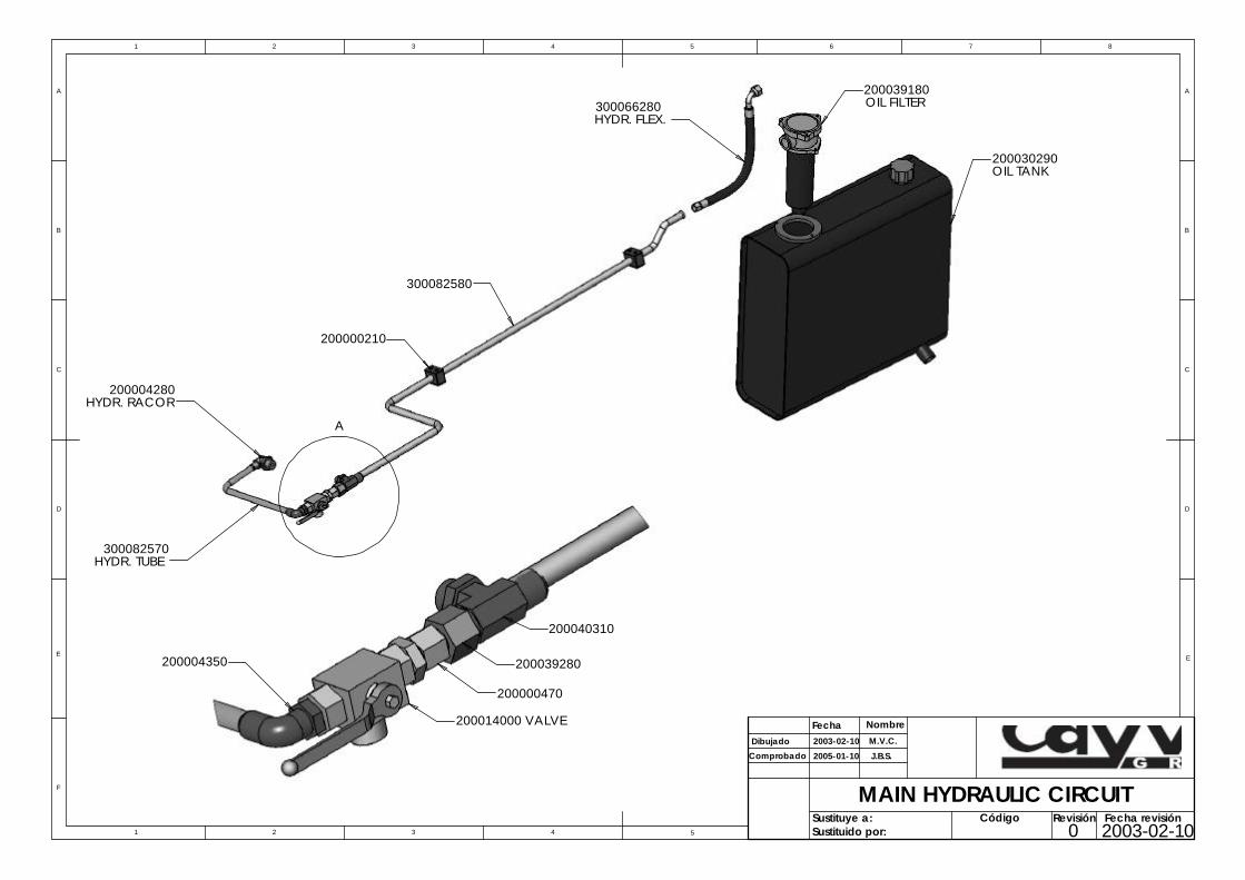
200014000 VALVE
200040310
200039280
200000470
200004350
200000210
300082580
OIL TANK
HYDR. TUBE300082570
HYDR. RACOR200004280
HYDR. FLEX.300066280 OIL FILTER
200039180
200030290
A
5
D
E
F
C
1 2 3 4
B
A
321 5
C
D
4 6 7 8
A
B
Sustituido por:Sustituye a:
2003-02-10
Fecha Nombre
Dibujado
Comprobado
M.V.C.
MAIN HYDRAULIC CIRCUIT
2005-01-10 J.B.S.Sociedad Cooperativa Catalana Limitada
Código 0
Revisión Fecha revisión2003-02-10
E
Sociedad Cooperativa Catalana Limitada
Código 0
Revisión Fecha revisión2003-02-105
D
E
F
C
1 2 3 4
B
A
321 5
C
D
4 6 7 8
A
B
Sustituido por:Sustituye a:
2003-02-10
Fecha Nombre
Dibujado
Comprobado
J. T. P.
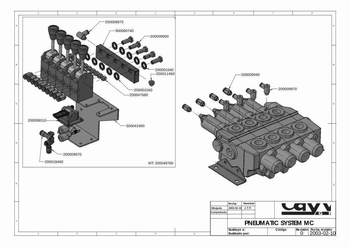
PNEUMATIC SYSTEM MC
E
200009970
200001040
300060740
200009970
200008010
200009940
200001040
300041960
200011460
200047680
KIT: 200049760
200009900
200009970
200018460
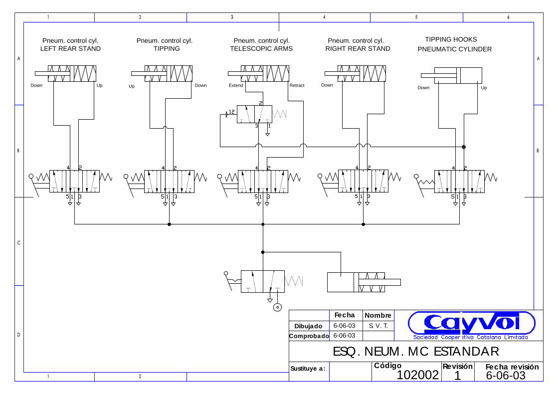
ESQ. NEUM. MC ESTANDARCódigo
102002
Comprobado
Dibujado
Fecha NombreS. V. T.
Sustituye a:
6-06-03
6-06-03
1Revisión Fecha revisión
6-06-03
Pneum. control cyl.TELESCOPIC ARMS
Down Up
LEFT REAR STANDPneum. control cyl.
Up Down Extend
Pneum. control cyl.TIPPING
Retract Down
Pneum. control cyl.RIGHT REAR STAND
UpDown
PNEUMATIC CYLINDERTIPPING HOOKS

S.V.T.2003-02-10
HIDRAULIC BRANCHEMENT MCBT 2003-02-100
J.B.S.2003-02-12
LEFT TIP LEFT REAR STAND CYLINDER
TELESCOPICBIG CYLINDER
TELESCOPICSMALL CYLINDER
RIGHT TIPCYLINDER
RIGHT REAR STAND CYLINDER CYLINDER
1030025
D
E
F
C
1 2 3 4
B
A
321 5
C
D
4 6 7 8
A
B
Sustituido por:Sustituye a:
Fecha Nombre
Dibujado
ComprobadoSociedad Cooperativa Catalana Limitada
Código
Revisión Fecha revisión
E
RIGHT REAR STAND CYL. RIGHT TIP CYL. LEFT TIP CYL. TEL. ARM BIG CYL. TEL. ARM SMALL CYL.
S.V.T.J.B.S.
0
2003-02-10
2003-02-10
2003-02-12
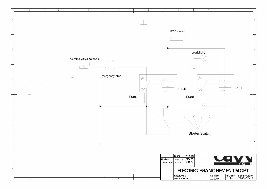
ELECTRIC BRANCHEMENT MCBT
101004Fecha revisión
5
D
E
F
C
1 2 3 4
B
A
321 5
C
D
4 6 7 8
A
B
Sustituido por:Sustituye a:
Fecha Nombre
Dibujado
ComprobadoSociedad Cooperativa Catalana Limitada
Código
Revisión
E
PTO switch
Work light
Fuse
RELE
Fuse
Emergency stop
Venting valve solenoid
Starter Switch
RELE