Embed Size (px)
Citation preview
From Vertices to Fragments:Rasterization
Reading Assignment: Chapter 7
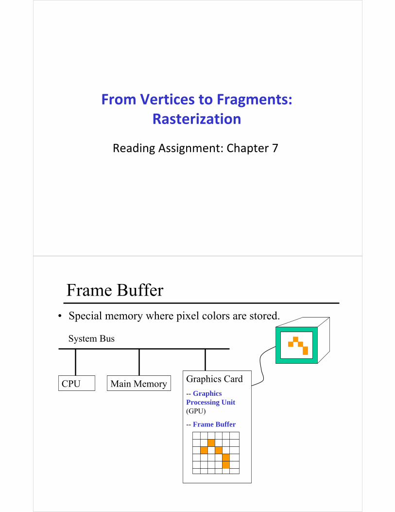
Frame Buffer
CPU Main Memory Graphics Card
-- Graphics Processing Unit(GPU)
-- Frame Buffer
System Bus
• Special memory where pixel colors are stored.
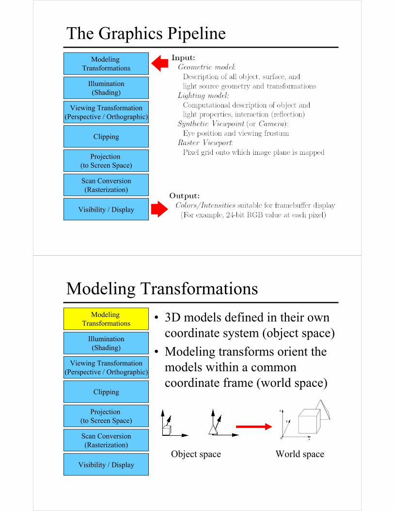
The Graphics PipelineModeling
Transformations
Illumination(Shading)
Viewing Transformation(Perspective / Orthographic)
Clipping
Projection (to Screen Space)
Scan Conversion(Rasterization)
Visibility / Display
Modeling Transformations
• 3D models defined in their own coordinate system (object space)
• Modeling transforms orient the models within a common coordinate frame (world space)
Modeling Transformations
Illumination(Shading)
Viewing Transformation(Perspective / Orthographic)
Clipping
Projection (to Screen Space)
Scan Conversion(Rasterization)
Visibility / DisplayObject space World space
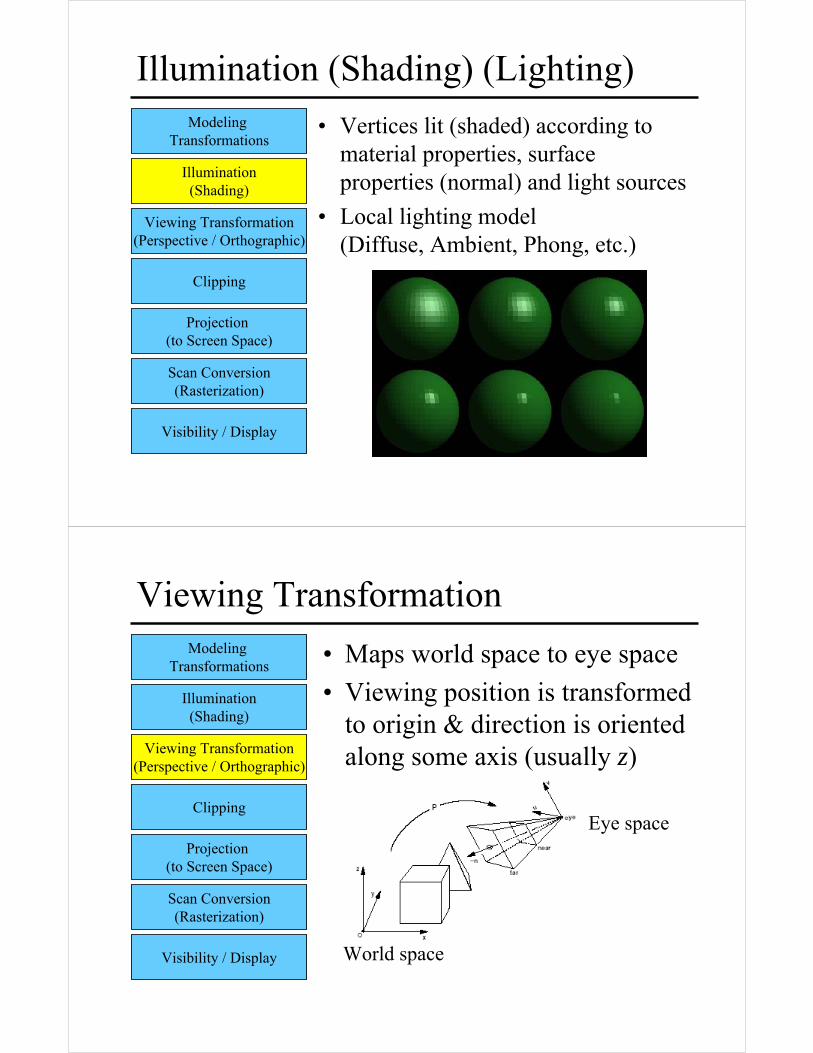
Illumination (Shading) (Lighting)
• Vertices lit (shaded) according to material properties, surface properties (normal) and light sources
• Local lighting model (Diffuse, Ambient, Phong, etc.)
Modeling Transformations
Illumination(Shading)
Viewing Transformation(Perspective / Orthographic)
Clipping
Projection (to Screen Space)
Scan Conversion(Rasterization)
Visibility / Display
Viewing Transformation
• Maps world space to eye space
• Viewing position is transformed to origin & direction is oriented along some axis (usually z)
Modeling Transformations
Illumination(Shading)
Viewing Transformation(Perspective / Orthographic)
Clipping
Projection (to Screen Space)
Scan Conversion(Rasterization)
Visibility / Display
Eye space
World space
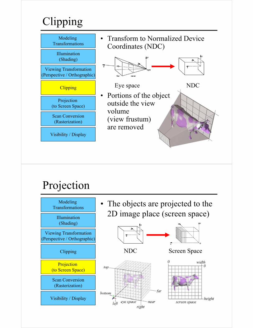
Clipping• Transform to Normalized Device
Coordinates (NDC)
• Portions of the object outside the view volume (view frustum) are removed
Modeling Transformations
Illumination(Shading)
Viewing Transformation(Perspective / Orthographic)
Clipping
Projection (to Screen Space)
Scan Conversion(Rasterization)
Visibility / Display
Eye space NDC
Projection
• The objects are projected to the 2D image place (screen space)
Modeling Transformations
Illumination(Shading)
Viewing Transformation(Perspective / Orthographic)
Clipping
Projection (to Screen Space)
Scan Conversion(Rasterization)
Visibility / Display
NDC Screen Space
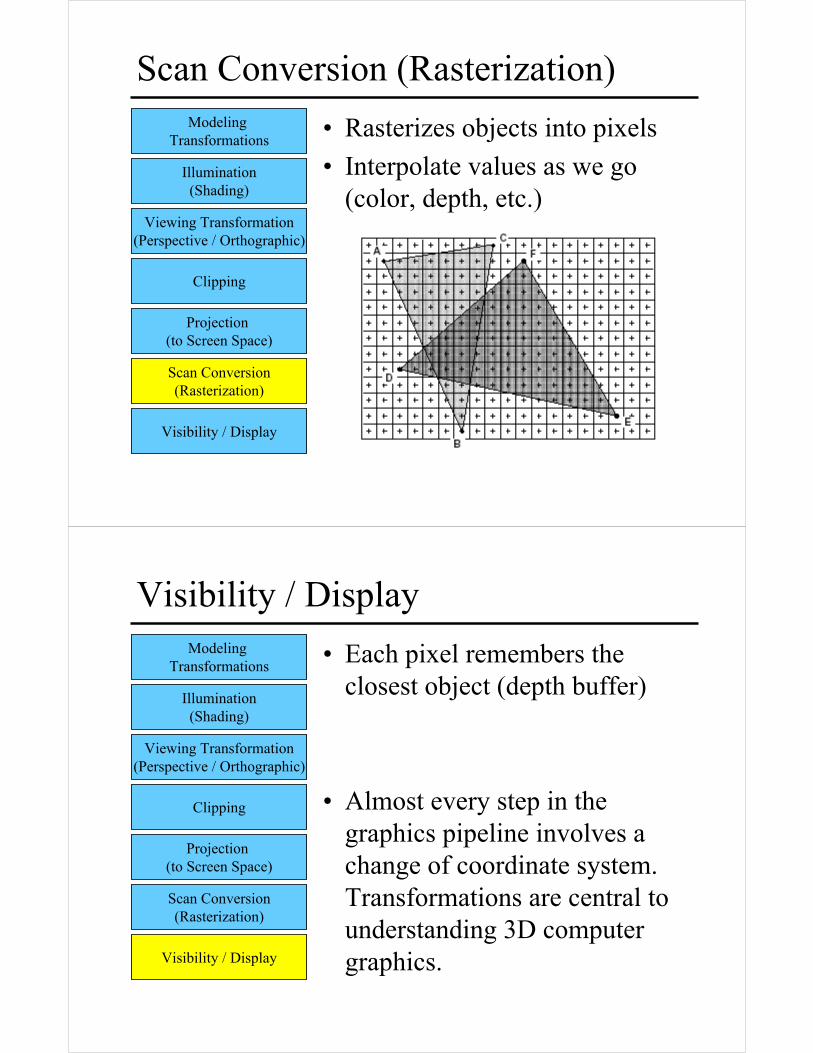
Scan Conversion (Rasterization)
• Rasterizes objects into pixels
• Interpolate values as we go (color, depth, etc.)
Modeling Transformations
Illumination(Shading)
Viewing Transformation(Perspective / Orthographic)
Clipping
Projection (to Screen Space)
Scan Conversion(Rasterization)
Visibility / Display
Visibility / Display
• Each pixel remembers the closest object (depth buffer)
• Almost every step in the graphics pipeline involves a change of coordinate system. Transformations are central to understanding 3D computer graphics.
Modeling Transformations
Illumination(Shading)
Viewing Transformation(Perspective / Orthographic)
Clipping
Projection (to Screen Space)
Scan Conversion(Rasterization)
Visibility / Display
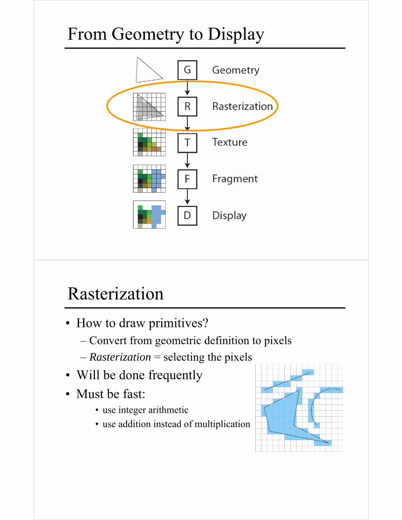
From Geometry to Display
• How to draw primitives?– Convert from geometric definition to pixels
– Rasterization = selecting the pixels
• Will be done frequently
• Must be fast: • use integer arithmetic
• use addition instead of multiplication
Rasterization
Next
• Line-drawing algorithm– naïve algorithm
– Bresenham algorithm
• Circle-drawing algorithm– naïve algorithm
– Bresenham algorithm
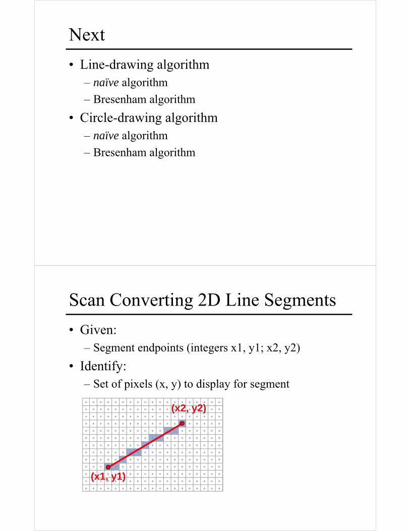
Scan Converting 2D Line Segments
• Given:– Segment endpoints (integers x1, y1; x2, y2)
• Identify:– Set of pixels (x, y) to display for segment
(x1, y1)
(x2, y2)
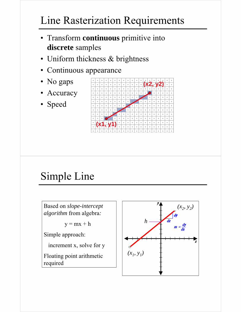
Line Rasterization Requirements
• Transform continuous primitive into discrete samples
• Uniform thickness & brightness
• Continuous appearance
• No gaps
• Accuracy
• Speed
(x1, y1)
(x2, y2)
Simple Line
Based on slope-intercept algorithm from algebra:
y = mx + h
Simple approach:
increment x, solve for y
Floating point arithmetic required
h
(x1, y1)
(x2, y2)
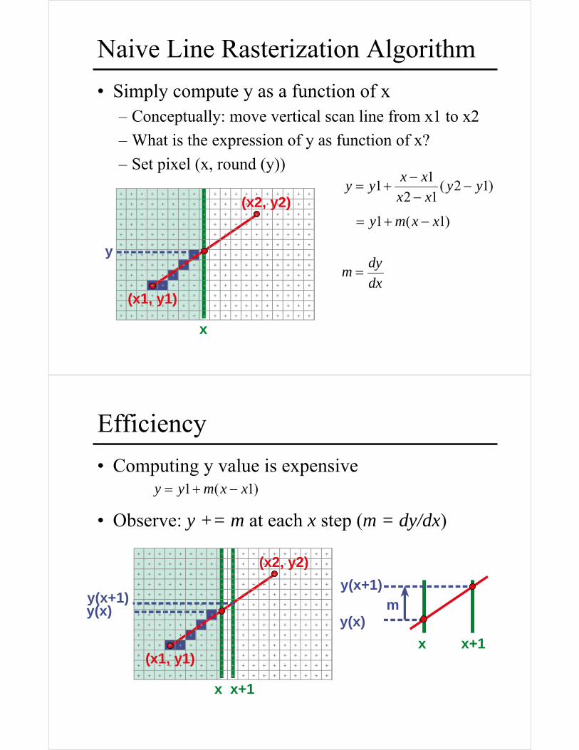
Naive Line Rasterization Algorithm
• Simply compute y as a function of x– Conceptually: move vertical scan line from x1 to x2
– What is the expression of y as function of x?
– Set pixel (x, round (y))
x
y
(x1, y1)
(x2, y2))1(1 xxmy −+=
)12(12
11 yy
xx
xxyy −
−−
+=
dx
dym =
Efficiency
• Computing y value is expensive
• Observe: y += m at each x step (m = dy/dx)
)1(1 xxmyy −+=
y(x+1)
y(x)
x x+1
m
x
y(x)
(x1, y1)
(x2, y2)
y(x+1)
x+1
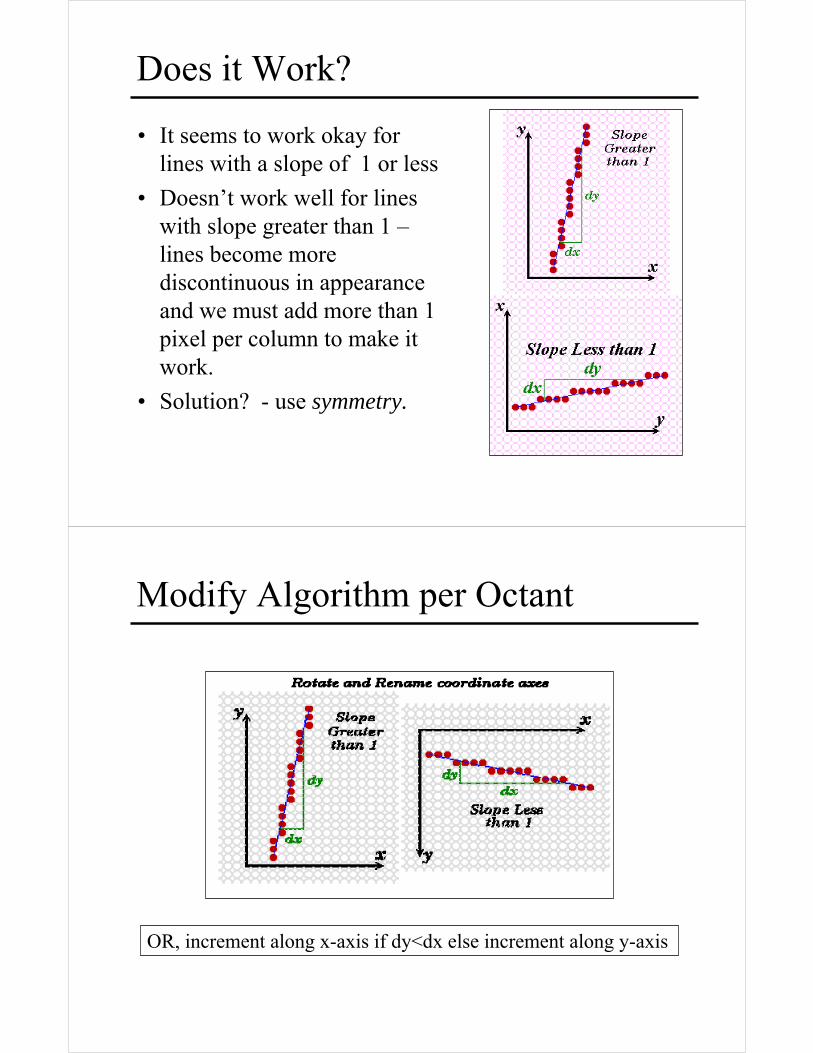
Does it Work?
• It seems to work okay for lines with a slope of 1 or less
• Doesn’t work well for lines with slope greater than 1 –lines become more discontinuous in appearance and we must add more than 1 pixel per column to make it work.
• Solution? - use symmetry.
Modify Algorithm per Octant
OR, increment along x-axis if dy<dx else increment along y-axis
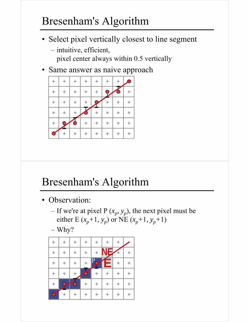
Bresenham's Algorithm
• Select pixel vertically closest to line segment– intuitive, efficient,
pixel center always within 0.5 vertically
• Same answer as naive approach
Bresenham's Algorithm
• Observation: – If we're at pixel P (xp, yp), the next pixel must be
either E (xp+1, yp) or NE (xp+1, yp+1)
– Why?
ENE
P
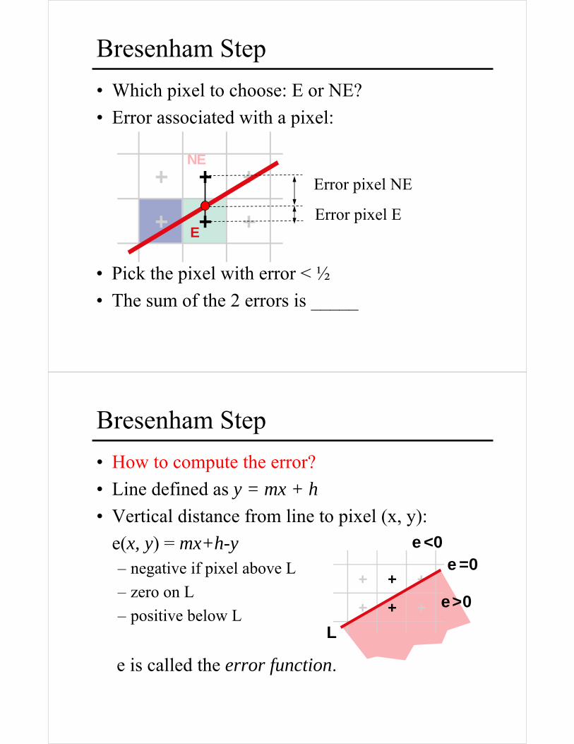
Bresenham Step
• Which pixel to choose: E or NE?
• Error associated with a pixel:
Error pixel NE
Error pixel EE
NE
• Pick the pixel with error < ½
• The sum of the 2 errors is _____
Bresenham Step
• How to compute the error?
• Line defined as y = mx + h
• Vertical distance from line to pixel (x, y):
e(x, y) = mx+h-y– negative if pixel above L
– zero on L
– positive below L
e is called the error function.
e>0
e <0e =0
L
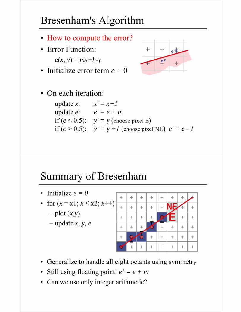
Bresenham's Algorithm
• How to compute the error?
• Error Function:e(x, y) = mx+h-y
• Initialize error term e = 0
• On each iteration:update x:update e:if (e ≤ 0.5): if (e > 0.5):
x' = x+1e' = e + my' = y (choose pixel E)y' = y +1 (choose pixel NE) e' = e - 1
e
e’
Summary of Bresenham
• Initialize e = 0
• for (x = x1; x ≤ x2; x++)
– plot (x,y)
– update x, y, e
• Generalize to handle all eight octants using symmetry
• Still using floating point! e’ = e + m
• Can we use only integer arithmetic?
ENE
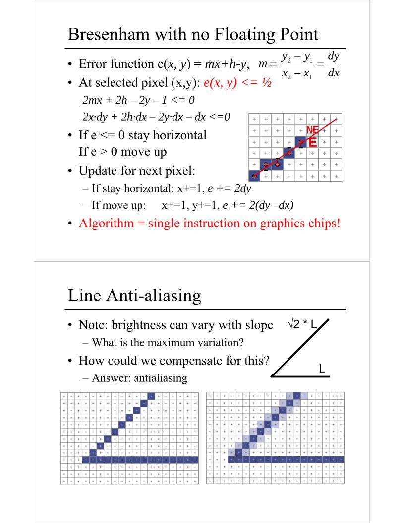
Bresenham with no Floating Point
• Error function e(x, y) = mx+h-y,
• At selected pixel (x,y): e(x, y) <= ½2mx + 2h – 2y – 1 <= 0
2x·dy + 2h·dx – 2y·dx – dx <=0
• If e <= 0 stay horizontalIf e > 0 move up
• Update for next pixel: – If stay horizontal: x+=1, e += 2dy
– If move up: x+=1, y+=1, e += 2(dy –dx)
• Algorithm = single instruction on graphics chips!
ENE
dx
dy
xx
yym =
−−
=12
12
Line Anti-aliasing
• Note: brightness can vary with slope– What is the maximum variation?
• How could we compensate for this?– Answer: antialiasing
√2 * L
L
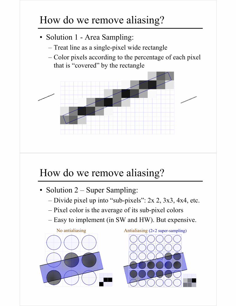
How do we remove aliasing?
• Solution 1 - Area Sampling:– Treat line as a single-pixel wide rectangle
– Color pixels according to the percentage of each pixel that is “covered” by the rectangle
How do we remove aliasing?
• Solution 2 – Super Sampling:– Divide pixel up into “sub-pixels”: 2x 2, 3x3, 4x4, etc.
– Pixel color is the average of its sub-pixel colors
– Easy to implement (in SW and HW). But expensive.
No antialiasing Antialiasing (2×2 super-sampling)
OpenGL Antialiasing
• Can enable separately for points, lines, or polygons
• For points and lines:
• For triangles:
glEnable(GL_POINT_SMOOTH);glEnable(GL_LINE_SMOOTH);
glEnable(GL_POLYGON_SMOOTH);
Next:
• Circle Rasterization

Circle Rasterization
• Generate pixels for 2nd octant only
• Slope progresses from 0 → –1
• Analog of BresenhamSegment Algorithm
Circle Rasterization: Naïve algorithm
• Circle equation: x2+y2-R2 = 0
• Simple algorithm:for x = xmin to xmax
y = sqrt(R*R - x*x)
draw pixel(x,y)
• Work by octants and use symmetry
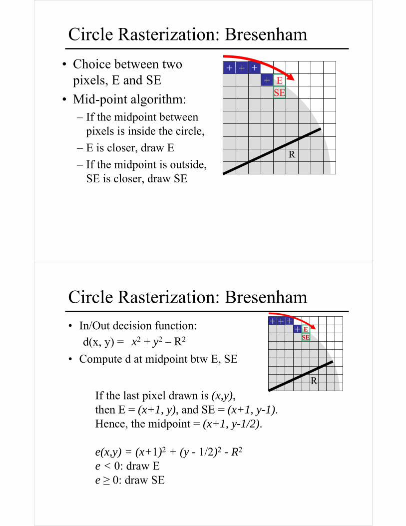
Circle Rasterization: Bresenham
• Choice between two pixels, E and SE
• Mid-point algorithm:– If the midpoint between
pixels is inside the circle,
– E is closer, draw E
– If the midpoint is outside, SE is closer, draw SE
R
+ + ++ E
SE
Circle Rasterization: Bresenham
• In/Out decision function:d(x, y) =
• Compute d at midpoint btw E, SE
If the last pixel drawn is (x,y), then E = (x+1, y), and SE = (x+1, y-1). Hence, the midpoint = (x+1, y-1/2).
e(x,y) = (x+1)2 + (y - 1/2)2 - R2
e < 0: draw Ee ≥ 0: draw SE
x2 + y2 – R2
R
+ + ++ E
SE
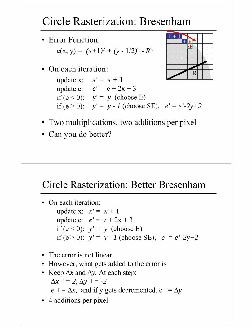
Circle Rasterization: Bresenham
• Error Function:e(x, y) =
• On each iteration:update x:update e:if (e < 0): if (e ≥ 0):
• Two multiplications, two additions per pixel
• Can you do better?
x' = x + 1e' = e + 2x + 3y' = y (choose E)y' = y - 1 (choose SE), e' = e’-2y+2
(x+1)2 + (y - 1/2)2 - R2
R
+ + ++ E
SE
Circle Rasterization: Better Bresenham
• On each iteration:update x:update e:if (e < 0): if (e ≥ 0):
• The error is not linear• However, what gets added to the error is• Keep Δx and Δy. At each step:
Δx += 2, Δy += -2e += Δx, and if y gets decremented, e += Δy
• 4 additions per pixel
x' = x + 1e' = e + 2x + 3y' = y (choose E)y' = y - 1 (choose SE), e' = e’-2y+2
Extensions to Other Functions
• Midpoint algorithm easy to extend to any curve defined by: f(x,y) = 0
• If the curve is polynomial, can be reduced to only additions using n-order differences
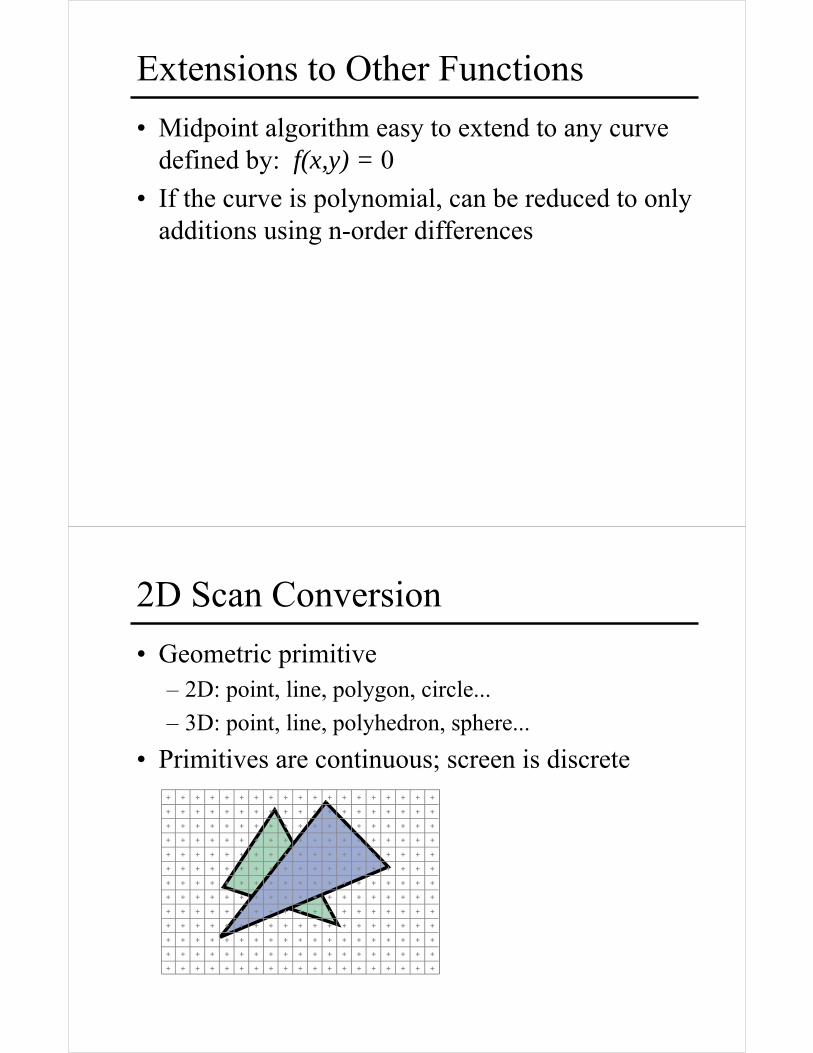
2D Scan Conversion
• Geometric primitive– 2D: point, line, polygon, circle...
– 3D: point, line, polyhedron, sphere...
• Primitives are continuous; screen is discrete
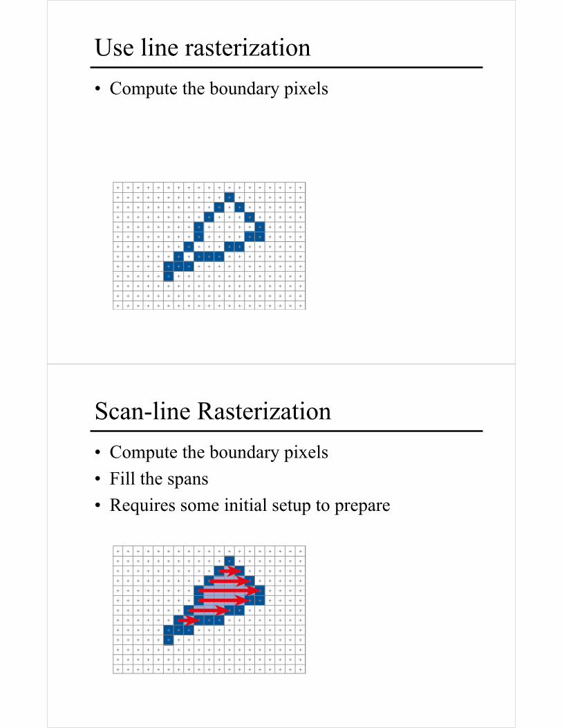
Use line rasterization
• Compute the boundary pixels
Scan-line Rasterization
• Compute the boundary pixels
• Fill the spans
• Requires some initial setup to prepare
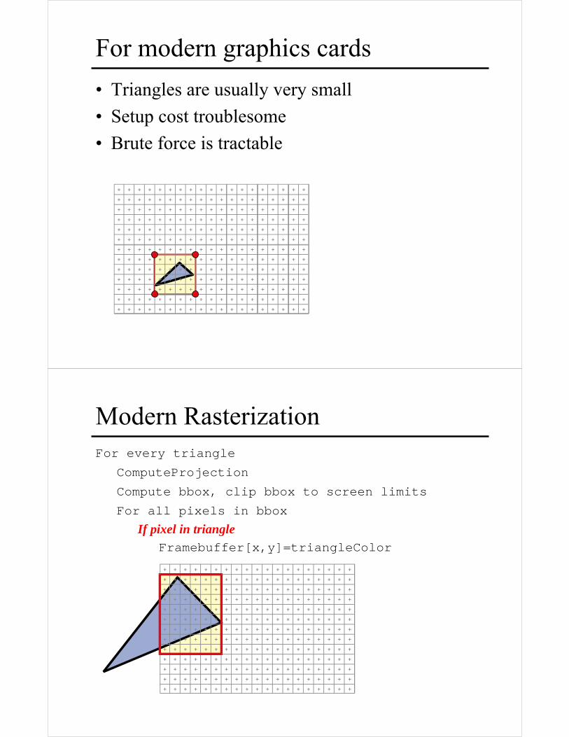
For modern graphics cards
• Triangles are usually very small
• Setup cost troublesome
• Brute force is tractable
Modern RasterizationFor every triangle
ComputeProjection
Compute bbox, clip bbox to screen limits
For all pixels in bbox
If pixel in triangleFramebuffer[x,y]=triangleColor


![Rasterization - University of Southern Californiarun.usc.edu/cs420-s14/lec13-rasterization/13-rasterization.pdfRasterization Scan Conversion Antialiasing [Ch 7.8-7.11, 8.9-8.12] 2](https://img.pdfslide.us/doc/110x75/5ad6e3997f8b9a9d5c8b6952/rasterization-university-of-southern-scan-conversion-antialiasing-ch-78-711.jpg)