Embed Size (px)
Citation preview

GRASS THE CATALOGUE350 05-2011
1
2
3
4
5
6
7
8
SPECIAL HINGES
From flap hinges and mini-hinges to glass door hinges for direct mountingon the cabinet side wall.

THE CATALOGUE GRASS 35105-2011
1
2
3
4
5
6
7
8
SPECIAL HINGES
Hinges for special applications.Where individual solutions are needed.
Opening angle
View Product descriptionFull
overlayHalf
overlayInset Page
90°
Flap hinge• Flap thicknesses up to 20 mm• Ø 35 mm cup hole• 3-dimensional adjustment
– – 352
90°
Mini-hinge A 90/E 90• Direct mounting on cabinet side wall• Cup Ø 26 mm• Ideal for doors with narrow frames
354
92°
Glass door hinge A 90GL/E 90GL• Direct mounting on cabinet side wall• Cup Ø 26 mm• Ideal for display cabinets
– 356
180°
180° glass door hinge• For glass thicknesses from 4 to 6 mm• Direct mounting on cabinet side wall• Fixing to the door without drilling
– – 358
210°
Glass door hinge +30/-30• For glass thicknesses from 5 to 6 mm• Universal application for cabinet angles from +30° to -30°• Fixing to the door without drilling
– – 360

Flap hinge.90° hinge with 35 mm cup. .
GRASS THE CATALOGUE Packaging units are not covered in this catalogue; please enquire with your supplier352 05-2011
1
2
3
4
5
6
7
8
FLAP HINGE 90° hinge with 35 mm cup
• 90° opening angle• For fl ap thicknesses up to 20 mm• Cup edge cover• Base and fl ap part are supplied
unassembled• Base and fl ap part have the same
drilling dimensions• 3-dimensional adjustment• Sturdy design
90°
ORDER INFORMATION
Door overlay ViewMaterial Item No.
Cup Arm Screw fi xing
Full overlayZamak,
nickel-platedZamak,
nickel-plated F078073799
Installation technology 757

Hinge systems.Special hinges.90° fl ap hinge
All dimensions in millimetres. Subject to changes THE CATALOGUE GRASS 35305-2011
1
2
3
4
5
6
7
8
HINGE SYSTEMS
SPECIAL HINGES
90° FLAP HINGE
INSTALLATION INFORMATION All dimensions in millimetres
Full overlay
3mm
0mm
14F
TS
1
12 16
Flap
thic
knes
s (T
S)
Minimum reveal (F)14 0.215 1.016 2.017 3.018 3.819 5.020 6.0
NUMBER OF HINGES NOTES
Fixing of fl ap and base parts with cylinder head screws (Ø 3 x 13 mm) (screws not sup-plied).
Hinge dimensions and reveal calculation with factory setting.
DRILLING PATTERNS
Version for screw fi xing
Ø 3
7.5
Ø 3
5
8.5 1mm
1mm
1mm
1mm
CUP DIMENSIONS
500
mm
800 mm
1200 mm
23

Mini-hinge A 90/E 90.With direct mounting on cabinet sidewall.
GRASS THE CATALOGUE Packaging units are not covered in this catalogue; please enquire with your supplier354 05-2011
1
2
3
4
5
6
7
8
MINI-HINGE A 90/E 90 90° hinge with 35 mm cup
• 90° opening angle• With Ø 26 mm cup hole, ideal
for doors with narrow frames• One-piece hinge• Three-point fi xing on cabinet is possible• Height adjustment by means of slots
90°
ORDER INFORMATION
Door overlay ViewMaterial Item No.
Cup Arm Screw fi xing
Full overlaySteel,
nickel-platedZamak,
nickel-plated F078073814
Half overlaySteel,
nickel-platedZamak,
nickel-plated F078073813
InsetSteel,
nickel-platedZamak,
nickel-plated F078073812
Installation technology 757

Hinge systems.Special hinges.Mini-hinge A 90/E 90
All dimensions in millimetres. Subject to changes THE CATALOGUE GRASS 35505-2011
1
2
3
4
5
6
7
8
HINGE SYSTEMS
SPECIAL HINGES
MINI-HINGE A 90/E 90
INSTALLATION INFORMATION All dimensions in millimetres
Full overlay A 90 Half overlay A 90 Inset E 9016
413
8
1322
7
TS
F
2332
(TS) = door thickness
Doo
r ov
erla
y
Cup distance15 416 517 6
Doo
r ov
erla
y
Cup distance6 47 58 6
Doo
r re
veal
(F)
Cup distance6 47 58 6
Position of holes for fi xing hinge to cabinet
32
10
16
32
108 7+TS
32
12
DRILLING PATTERNS
Version for screw fi xing
CUP DIMENSIONS

Glass door hinge A 90GL/E 90GL.For direct mounting on cabinet side wall.
GRASS THE CATALOGUE Packaging units are not covered in this catalogue; please enquire with your supplier356 05-2011
1
2
3
4
5
6
7
8
GLASS DOOR HINGE A 90GL/E 90GL For direct mounting on cabinet side wall
• 92° opening angle• One-piece glass door hinge• Ideal for display cabinets• 3-point fi xing on cabinet is possible• Height adjustment by means of slots
92°
ORDER INFORMATION
Door overlay ViewMaterial Item No.
Cup Arm
Half overlay Plastic, blackZamak,
nickel-plated F078073786
Inset Plastic, blackZamak,
nickel-plated F078073787
DECORATIVE COVER CAPS
Designation Item No.
Nickel velour F069073420
Nickel polished, eroded F069073421
Brass polished, eroded F069073422
Brass velour F069073423
Silver RAL 9006 F069073410
Black F069073424
Designation Item No.
Nickel velour F069073425
Stainless steel F069073426
Nickel polished, eroded F069073414
Brass polished, eroded F069073427
Brass velour F069073416
Silver RAL 9006 F069073417
Black F069073428
Chrome fi nish F069073419
Installation technology 757

Hinge systems.Special hinges.Glass door hinge A 90GL/E 90GL
All dimensions in millimetres. Subject to changes THE CATALOGUE GRASS 35705-2011
1
2
3
4
5
6
7
8
HINGE SYSTEMS
SPECIAL HINGES
GLASS DOOR HINGE A 90GL/E 90GL
INSTALLATION INFORMATION All dimensions in millimetres
Half overlay A 90GL Inset E 90GL8
2211
4-6
(TS)
TS +
8
3221
F
9
(TS) = door thickness
Doo
r ov
erla
y
Cup distance6 47 58 6
Doo
r re
veal
(F)
Cup distance4 43 52 6
Position of holes for fi xing hinge to cabinet
32
108 17+TS
32
12
DRILLING PATTERNS
26+0.1
4-6
31
39
26+0.1
31
4-6
CUP DIMENSIONS
4 -6
Ø 26+0.1

Glass door hinge.180° for direct mounting on cabinet side wall.
GRASS THE CATALOGUE Packaging units are not covered in this catalogue; please enquire with your supplier358 05-2011
1
2
3
4
5
6
7
8
GLASS DOOR HINGE 180° for direct mounting on cabinet side wall
• 180° opening angle• Particularly fl at design• Fixing to the door without drilling• For glass thicknesses from 4 to 6 mm
180°
ORDER INFORMATION
Door overlay View PositionMaterial Item No.
Cup Arm
Inset
1
Zamak, nickel-plated
Zamak, nickel-plated
F078073792
2
1 Left at the top / right at the bottom2 Right at the top / left at the bottom
PULL
Designation Item No.
Zamak, nickel-plated, fi xing with self-adhesive pad F069073457
Installation technology 757
Hinge systems.Special hinges.180° glass door hinge
All dimensions in millimetres. Subject to changes THE CATALOGUE GRASS 35905-2011
1
2
3
4
5
6
7
8
HINGE SYSTEMS
SPECIAL HINGES
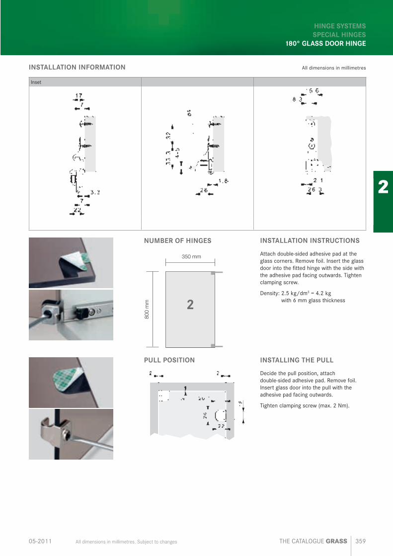
180° GLASS DOOR HINGE
INSTALLATION INFORMATION All dimensions in millimetres
Inset
NUMBER OF HINGES
350 mm
800
mm 2
INSTALLATION INSTRUCTIONS
Attach double-sided adhesive pad at the glass corners. Remove foil. Insert the glass door into the fi tted hinge with the side with the adhesive pad facing outwards. Tighten clamping screw.
Density: 2.5 kg/dm3 = 4.2 kg with 6 mm glass thickness
PULL POSITION INSTALLING THE PULL
Decide the pull position, attach double-sided adhesive pad. Remove foil. Insert glass door into the pull with the adhesive pad facing outwards.
Tighten clamping screw (max. 2 Nm).

Glass door hinge.+30° to -30° variable-angle glass and mirror door hinge.
GRASS THE CATALOGUE Packaging units are not covered in this catalogue; please enquire with your supplier360 05-2011
1
2
3
4
5
6
7
8
GLASS DOOR HINGE +30° to -30° variable-angle glass and mirror door hinge
• 210° opening angle• Universal application for cabinet
angles from +30° to -30°• Fixing to the door without drilling• Ideal for small doors• For glass thicknesses from 5 to 6 mm
ORDER INFORMATION
Door overlay View PositionMaterial Item No.
Cup Arm
Full overlay
1
Zamak, nickel-plated
Zamak, nickel-plated
F078073783
2
Zamak, nickel-plated
Zamak, nickel-plated
F078073785
1 Left at the top / right at the bottom2 Right at the top / left at the bottom
PULL
Designation Item No.
Zamak, nickel-plated, fi xing with self- adhesive pad F069073457
Installation technology 757
210°
Hinge systems.Special hinges.Glass door hinge +30/-30
All dimensions in millimetres. Subject to changes THE CATALOGUE GRASS 36105-2011
1
2
3
4
5
6
7
8
HINGE SYSTEMS
SPECIAL HINGES
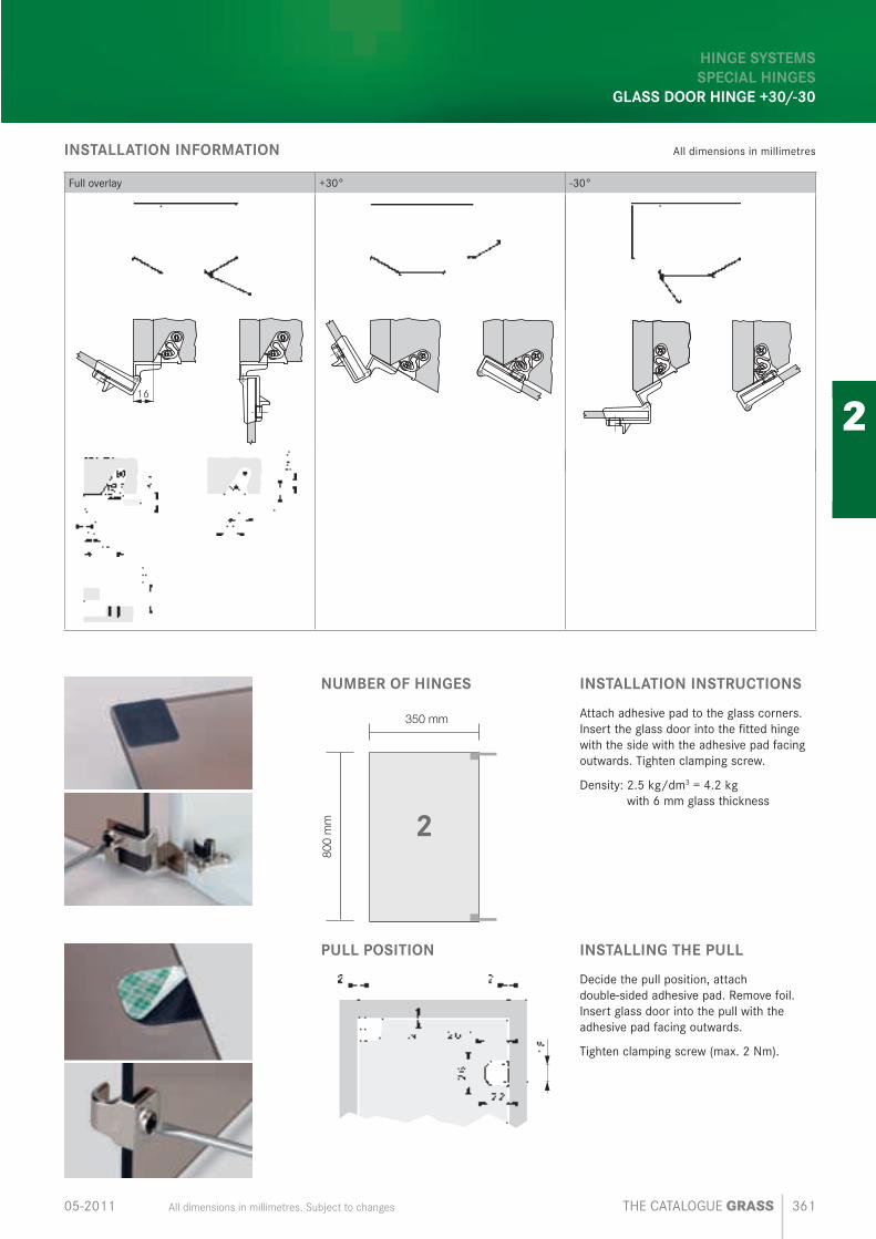
GLASS DOOR HINGE +30/-30
INSTALLATION INFORMATION All dimensions in millimetres
Full overlay +30° -30°
16
NUMBER OF HINGES
350 mm
800
mm 2
INSTALLATION INSTRUCTIONS
Attach adhesive pad to the glass corners. Insert the glass door into the fi tted hinge with the side with the adhesive pad facing outwards. Tighten clamping screw.
Density: 2.5 kg/dm3 = 4.2 kg with 6 mm glass thickness
PULL POSITION INSTALLING THE PULL
Decide the pull position, attach double-sided adhesive pad. Remove foil. Insert glass door into the pull with the adhesive pad facing outwards.
Tighten clamping screw (max. 2 Nm).