Embed Size (px)
Citation preview
28 CAN Newsletter 3/2016
The demands on the development and testing of embedded systems have never been as high as today.
Therefore, the performance of the test process has to be enhanced, for instance by the use of scalable test systems.
Because of digitalization and artificial intelligence, the technical progress in the field of embedded systems development is increasing rapidly, for example in auto-motive applications. The complexity of functions and the development effort are rising constantly. So, to reach the necessary depth of testing in an economic manner, mod-ule and system tests have to be realized by the highest possible grade of automation in the process. The general demands on the tests and the complex control systems have increased the demands on the development as well.
When developing the software that will be imple-mented in the target hardware and in order to bring the control system into an operating condition that is usable for the developer, more and more complex emulations of the system environment by simula-tion are necessary. Because of the continuously rising demands on embedded systems and because of the automatically generated soft-ware out of models, efforts in the test process escalade disproportionately high.
Composition of the test system
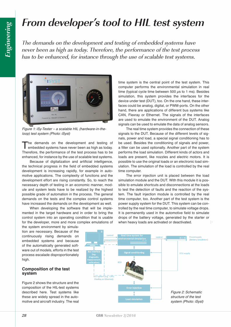
Figure 2 shows the structure and the composition of the HIL-test systems described here. Test systems like these are widely spread in the auto-motive and aircraft industry. The real
From developer’s tool to HIL test system
The demands on the development and testing of embedded systems have never been as high as today. Therefore, the performance of the test process has to be enhanced, for instance through the use of scalable test systems.
time system is the central point of the test system. This computer performs the environmental simulation in real time (typical cycle time between 500 µs to 1 ms). Besides simulation, this system provides the interfaces for the device under test (DUT), too. On the one hand, these inter-faces could be analog, digital, or PWM-ports. On the other hand, there are applications of different bus systems like CAN, Flexray or Ethernet. The signals of the interfaces are used to emulate the environment of the DUT. Analog signals can be used to emulate the data of analog sensors.
The real time system provides the connection of these signals to the DUT. Because of the different levels of sig-nals, power and load, a special signal conditioning has to be used. Besides the conditioning of signals and power, a filter can be used optionally. Another part of the system performs the load simulation. Different kinds of actors and loads are present, like nozzles and electric motors. It is possible to use the original loads or an electronic load sim-ulation. The simulation of the load is controlled by the real time computer.
The error injection unit is placed between the load simulation module and the DUT. With this module it is pos-sible to emulate shortcuts and disconnections at the loads to test the detection of faults and the reaction of the sys-tem. The fault injection module is controlled by the real time computer, too. Another part of the test system is the power supply system for the DUT. This system can be con-trolled by the real time computer, to simulate voltage drops. It is permanently used in the automotive field to simulate drops of the battery voltage, generated by the starter or when heavy loads are activated or deactivated.
Figure 1: iSy-Tester – a scalable HIL (hardware-in-the-loop) test system (Photo: iSyst)
Figure 2: Schematic structure of the test system (Photo: iSyst)
Engi
neer
ing
The last part of the test system is the control com-puter unit. This personal computer is mostly based on Win-dows. It is used to control automatic tests as well as manual tests. The automation of the tests can be done by different tools (e.g. iSy-Tester or sepp.med Cetes++) and with differ-ent description languages (e.g. Python or UML). Other tools are used for monitoring the activity of communication on the bus (e.g. Vector’s CANalyzer) or to be able to get access to the software of the control system during the term (e.g. Vec-tor’s CANape, iSystem’s Winidea, or Lauterbach’s Trace32). These tools widen the possibilities of the automatic tests.
The implementation of the environmental simulation can be achieved by using different programming languages with a fixed cycle time of typically 1 ms. According to the demands on the test, the complexity of the model of the envi-ronment and the processing power, cycle times down to 50 µs are possible. Within this time period all inputs and outputs are handled as well as the calculation of one simulation step of the complete simulation model.
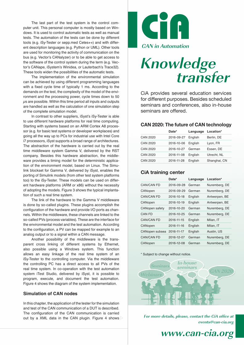
In contrast to other suppliers, iSyst’s iSy-Tester is able to use different hardware platforms for real time computing. Starting with systems based on an ARM Cortex A8 proces-sor (e.g. for basic test systems or developer workplaces) and going all the way up to PCs for industrial use with Intel Core i7 processors, iSyst supports a broad range of architectures. The abstraction of the hardware is carried out by the real time middleware system Gamma V, delivered by the RST company. Besides this hardware abstraction, the middle-ware provides a timing model for the deterministic applica-tion of the environment model, based on Linux. The Simu-link blockset for Gamma V, delivered by iSyst, enables the porting of Simulink models (from other test system platforms too) to the iSy-Tester. These models can be used on differ-ent hardware platforms (ARM or x86) without the necessity of adopting the models. Figure 3 shows the typical implanta-tion of such a real time system.
The link of the hardware to the Gamma V middleware is done by so-called plugins. These plugins accomplish the configuration of the hardware and provide I/O ports as chan-nels. Within the middleware, these channels are linked to the so-called PVs (process variables). These are the interface for the environmental model and the test automation. According to the configuration, a PV can be mapped for example to an analog output or to a signal within a CAN message.
Another possibility of the middleware is the trans-parent cross linking of different systems by Ethernet, also possible using a Windows system. This function allows an easy linkage of the real time system of an iSy-Tester to the controlling computer. Via the middleware the controlling PC has a direct access to all PVs of the real time system. In co-operation with the test automation system iTest Studio, delivered by iSyst, it is possible to program, execute, and document the test automation. Figure 4 shows the diagram of the system implementation.
Simulation of CAN nodes
In this chapter, the application of the tester for the simulation and test of the CAN communication of a DUT is described. The configuration of the CAN communication is carried out by a XML data in the CAN plugin. Figure 4 shows
* Subject to change without notice.
CiA provides several education services for different purposes. Besides scheduled seminars and conferences, also in-house seminars are offered.
CiACAN in Automation
Knowledge transfer
For more details, please, contact the CiA office at [email protected]
www.can-cia.org
CiA training centerDate* Language Location*
CAN/CAN FD 2016-09-28 German Nuremberg, DE
CANopen 2016-09-29 German Nuremberg, DE
CAN/CAN FD 2016-10-18 English Antwerpen, BE
CANopen 2016-10-19 English Antwerpen, BE
CANopen safety 2016-10-20 German Nuremberg, DE
CAN FD 2016-10-25 German Nuremberg, DE
CAN/CAN FD 2016-11-15 English Milan, IT
CANopen 2016-11-16 English Milan, IT
CANopen subsea 2016-11-17 English Austin, US
CAN/CAN FD 2016-12-07 German Nuremberg, DE
CANopen 2016-12-08 German Nuremberg, DE
CAN 2020: The future of CAN technologyDate* Language Location*
CAN 2020 2016-09-27 English Berlin, DE
CAN 2020 2016-10-06 English Lyon, FR
CAN 2020 2016-10-27 German Essen, DE
CAN 2020 2016-11-08 English Utrecht, NL
CAN 2020 2016-11-28 English Shanghai, CN
30 CAN Newsletter 3/2016
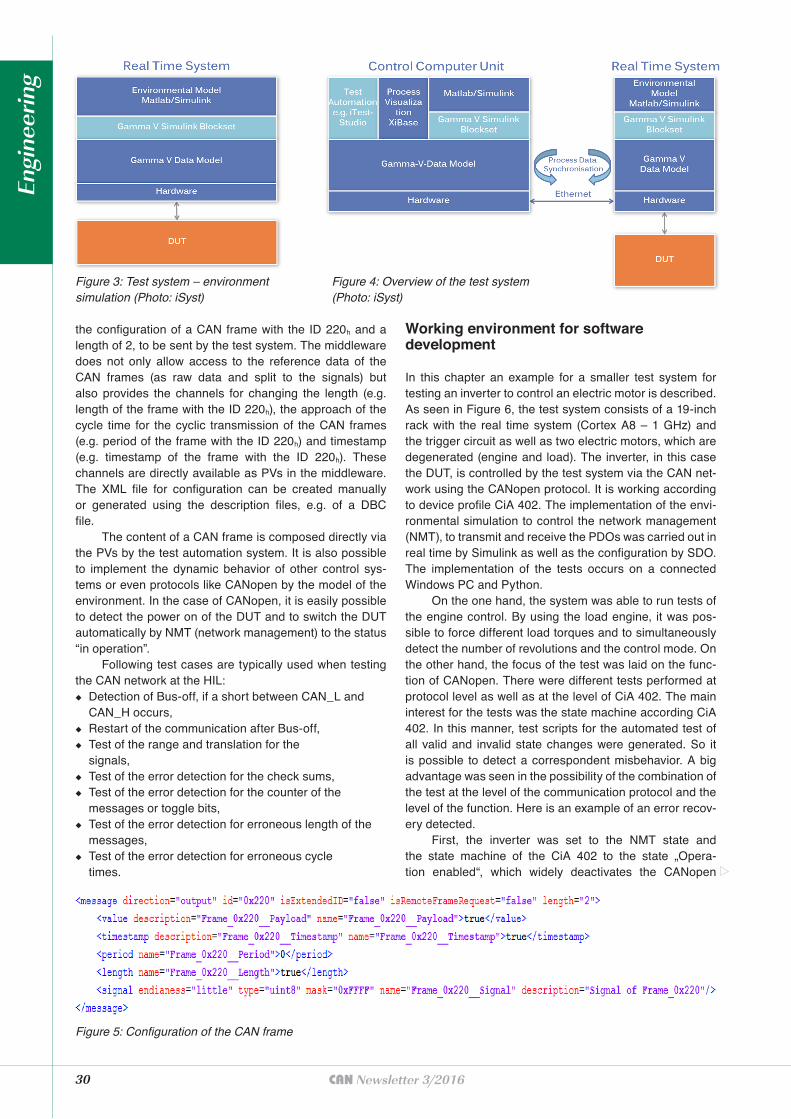
the configuration of a CAN frame with the ID 220h and a length of 2, to be sent by the test system. The middleware does not only allow access to the reference data of the CAN frames (as raw data and split to the signals) but also provides the channels for changing the length (e.g. length of the frame with the ID 220h), the approach of the cycle time for the cyclic transmission of the CAN frames (e.g. period of the frame with the ID 220h) and timestamp (e.g. timestamp of the frame with the ID 220h). These channels are directly available as PVs in the middleware. The XML file for configuration can be created manually or generated using the description files, e.g. of a DBC file.
The content of a CAN frame is composed directly via the PVs by the test automation system. It is also possible to implement the dynamic behavior of other control sys-tems or even protocols like CANopen by the model of the environment. In the case of CANopen, it is easily possible to detect the power on of the DUT and to switch the DUT automatically by NMT (network management) to the status “in operation”.
Following test cases are typically used when testing the CAN network at the HIL:
◆ Detection of Bus-off, if a short between CAN_L and CAN_H occurs,
◆ Restart of the communication after Bus-off, ◆ Test of the range and translation for the
signals, ◆ Test of the error detection for the check sums, ◆ Test of the error detection for the counter of the
messages or toggle bits, ◆ Test of the error detection for erroneous length of the
messages, ◆ Test of the error detection for erroneous cycle
times.
Working environment for software development
In this chapter an example for a smaller test system for testing an inverter to control an electric motor is described. As seen in Figure 6, the test system consists of a 19-inch rack with the real time system (Cortex A8 – 1 GHz) and the trigger circuit as well as two electric motors, which are degenerated (engine and load). The inverter, in this case the DUT, is controlled by the test system via the CAN net-work using the CANopen protocol. It is working according to device profile CiA 402. The implementation of the envi-ronmental simulation to control the network management (NMT), to transmit and receive the PDOs was carried out in real time by Simulink as well as the configuration by SDO. The implementation of the tests occurs on a connected Windows PC and Python.
On the one hand, the system was able to run tests of the engine control. By using the load engine, it was pos-sible to force different load torques and to simultaneously detect the number of revolutions and the control mode. On the other hand, the focus of the test was laid on the func-tion of CANopen. There were different tests performed at protocol level as well as at the level of CiA 402. The main interest for the tests was the state machine according CiA 402. In this manner, test scripts for the automated test of all valid and invalid state changes were generated. So it is possible to detect a correspondent misbehavior. A big advantage was seen in the possibility of the combination of the test at the level of the communication protocol and the level of the function. Here is an example of an error recov-ery detected.
First, the inverter was set to the NMT state and the state machine of the CiA 402 to the state „Opera-tion enabled“, which widely deactivates the CANopen
Figure 5: Configuration of the CAN frame
Figure 3: Test system – environment simulation (Photo: iSyst)
Figure 4: Overview of the test system (Photo: iSyst)
Engi
neer
ing
31CAN Newsletter 3/2016
communication (beside NMT commands). Thus, it was no longer possible to control the driving engine. The forced revolution speed was constant. In the view of safety this is a critical stage.
Example of use – fullsize HIL
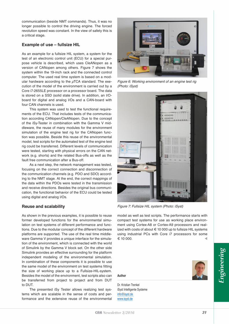
As an example for a fullsize HIL system, a system for the test of an electronic control unit (ECU) for a special pur-pose vehicle is described, which uses CleANopen as a version of CANopen among others. Figure 7 shows the system within the 19-inch rack and the connected control computer. The used real time system is based on a mod-ular hardware according to the µTCA standard. The exe-cution of the model of the environment is carried out by a Core i7-2655LE processor on a processor board. The data is stored on a SSD (solid state drive). In addition, an I/O-board for digital and analog I/Os and a CAN-board with four CAN channels is used.
This system was used to test the functional require-ments of the ECU. That includes tests of the communica-tion according CANopen/CleANopen. Due to the concept of the iSy-Tester in combination with the Gamma V mid-dleware, the reuse of many modules for the environment simulation of the engine test rig for the CANopen func-tion was possible. Beside this reuse of the environmental model, test scripts for the automated test of the engine test rig could be transferred. Different levels of communication were tested, starting with physical errors on the CAN net-work (e.g. shorts) and the related Bus-offs as well as the fault free communication after a Bus-off.
As a next step, the network management was tested, focusing on the correct connection and disconnection of the communication channels (e.g. PDO and SDO) accord-ing to the NMT stage. At the end, the correct mappings of the data within the PDOs were tested in the transmission and receive directions. Besides the original bus communi-cation, the functional behavior of the ECU could be tested using digital and analog I/Os.
Reuse and scalability
As shown in the previous examples, it is possible to reuse former developed functions for the environmental simu-lation on test systems of different performance and func-tions. Due to the modular concept of the different hardware platforms are supported. The use of the real time middle-ware Gamma V provides a unique interface for the simula-tion of the environment, which is connected with the world of Simulink by the Gamma V block set. On the other side Simulink provides an effective surrounding for the platform independent modeling of the environmental simulation. In combination of these components it is possible to use the same model of the environment on test systems fitting the size of working place up to a Fullsize-HIL-system. Besides the model of the environment, test scripts also can be transferred from project to project and from DUT to DUT.
The presented iSy Tester allows realizing test sys-tems which are scalable in the sense of costs and per-formance and the extensive reuse of the environmental
model as well as test scripts. The performance starts with compact test systems for use as working place environ-ment using Cortex-A8 or Cortex-A9 processors and real-ized with costs of about € 10 000 up to fullsize HIL systems using industrial PCs with Core i7 processors for some € 10 000. t
Figure 6: Working environment of an engine test rig (Photo: iSyst)
Figure 7: Fullsize HIL system (Photo: iSyst)
Author
Dr. Kristian TrenkeliSyst Intelligente [email protected] www.isyst.de
Engi
neer
ing