Embed Size (px)
Citation preview
© 2013 WIT Press, www.witpress.comISSN: 1755-7437 (paper format), ISSN: 1755-7445 (online), http://journals.witpress.comDOI: 10.2495/DNE-V8-N3-191-212
E. Andrada, et al., Int. J. of Design & Nature and Ecodynamics. Vol. 8, No. 3 (2013) 191–212
FROM BIOMECHANICS OF RATS’ INCLINED LOCOMOTION TO A CLIMBING ROBOT
E. ANDRADA1,2, J. MÄMPEL1,3, A. SCHMIDT4, M.S. FISCHER4, A. KARGUTH3 & H. WITTE1
1Chair of Biomechatronics, Technische Universität Ilmenau, D-98693 Ilmenau, Germany.2Science of Motion, Friedrich-Schiller Universität, D-07749 Jena, Germany.
3TETRA Gesellschaft für Sensorik, Robotik und Automation mbH, Germany.4Institut für Spezielle Zoologie und Evolutionsbiologie mit Phyletischem Museum,
Friedrich-Schiller-Universität, D-07743 Jena, Germany.
ABSTRACTThe base of the design and construction of an adaptive light-weight climbing robot is an understanding of the adaptive nature of small mammals’ motion on sloped supports. In the present study, the locomotor generalist Rattus norvegicus (the rat) served as the main biological paragon. Experiments were performed under X-ray high-speed videography with synchronized substrate reaction force (SRF) measurements, to allow calculation of inverse dynamics. Statistical analyses were performed to examine the effects of different substrate orienta-tions on the kinematic variables. We obtained SRFs, torque and power patterns in the extremities and trunk of rats moving on simulated arboreal substrates at different substrate orientations (0°, 30°, 60°). During locomo-tion on horizontal substrates, rats prefer symmetrical gaits and switch to synchronous gaits at 60° inclination. Surprisingly, horizontal locomotion and locomotion on moderately inclined substrates (30°) differ only in the power invested in locomotion. Our results suggest that the trunk seems to play a more important role during locomotion at steeper inclines where rats switch to the more quasi-static in-phase gait. We conclude that this may be an indication of a change from a grounded to a climbing gait. Via bionic transfer we derived main basic principles, which we applied to the design of the robot Rat-Nic.Keywords: Biologically inspired robots, biomechanics, inverse dynamics, rat locomotion.
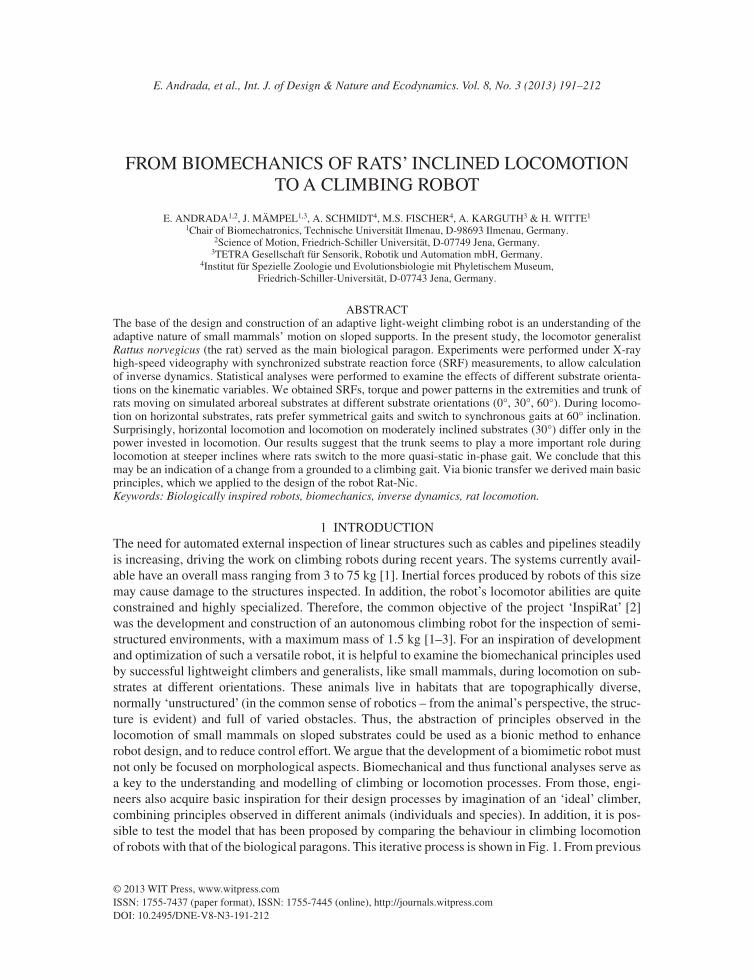
1 INTRODUCTIONThe need for automated external inspection of linear structures such as cables and pipelines steadily is increasing, driving the work on climbing robots during recent years. The systems currently avail-able have an overall mass ranging from 3 to 75 kg [1]. Inertial forces produced by robots of this size may cause damage to the structures inspected. In addition, the robot’s locomotor abilities are quite constrained and highly specialized. Therefore, the common objective of the project ‘InspiRat’ [2] was the development and construction of an autonomous climbing robot for the inspection of semi-structured environments, with a maximum mass of 1.5 kg [1–3]. For an inspiration of development and optimization of such a versatile robot, it is helpful to examine the biomechanical principles used by successful lightweight climbers and generalists, like small mammals, during locomotion on sub-strates at different orientations. These animals live in habitats that are topographically diverse, normally ‘unstructured’ (in the common sense of robotics – from the animal’s perspective, the struc-ture is evident) and full of varied obstacles. Thus, the abstraction of principles observed in the locomotion of small mammals on sloped substrates could be used as a bionic method to enhance robot design, and to reduce control effort. We argue that the development of a biomimetic robot must not only be focused on morphological aspects. Biomechanical and thus functional analyses serve as a key to the understanding and modelling of climbing or locomotion processes. From those, engi-neers also acquire basic inspiration for their design processes by imagination of an ‘ideal’ climber, combining principles observed in different animals (individuals and species). In addition, it is pos-sible to test the model that has been proposed by comparing the behaviour in climbing locomotion of robots with that of the biological paragons. This iterative process is shown in Fig. 1. From previous
192 E. Andrada, et al., Int. J. of Design & Nature and Ecodynamics. Vol. 8, No. 3 (2013)
works on terrestrial locomotion of small vertebrates, we knew about the importance of sagittal spinal movements during in-phase gaits, which contribute up to 50% to the total spatial gain [4, 5]. In addi-tion, we knew that the coordination between trunk and extremities especially for in-phase gaits is of great importance for stable locomotion, providing mechanical ‘robustness’ [6]. But the contribution of the trunk to body propulsion on sloped substrates at the beginning of our project was unknown. We decided to use rats as biological paragons due to their success as ecological generalists (‘ubi-quists’). Then, following a bionic approach, we intended to infer and summarize some biomechanical strategies and behaviour during inclined locomotion by estimating forces, torques and power in the extremities and trunk of rats moving on a simulated arboreal substrate at different orientations (0°, 30° and 60°). This was achieved by using X-ray videography with synchronized substrate reaction force (SRF) measurements to calculate inverse dynamics (IDA).
The main part of this paper is devoted to the experimental and the biomechanical approach. Our specifi c biomechanical goals were threefold. First, we examined whether gait modes, temporal gait parameters and, therefore, joint kinematics and kinetics are grade-related. Based on observations in horses and lizards [7, 8], according to the principles of energy conservation, we expected that ener-getic cost increases during incline locomotion. Thus, we hypothesized that the rats change speed and/or gait to deal with increasing limb joint torques and powers. For conservative systems as incli-nation increases, grade-related changes in potential energy require that an animal expends more energy to move uphill at the same speed as on the horizontal. However, small animals like any objects of the real-world are non-conservative systems, and, as shown by Hanna et al. [9], the
Figure 1: Design process in the development of a biologically inspired robot. The technical design process should be based on semantic and dynamical models, deduced from biomechanical studies.
E. Andrada, et al., Int. J. of Design & Nature and Ecodynamics. Vol. 8, No. 3 (2013) 193
metabolic cost of vertical climbing and horizontal walking in small primates with a mass below 0.5 kg at the same speed is almost the same. More effi cient horizontal walking is related to an increased leg length. Phylogenetic leg length increments permit the use of energy saving mecha-nisms such as pendular mechanics [10, 11], reducing at the same time the rate at which muscles are activated to generate force to support body mass, as initially reported for running [12].
We were also interested in whether the contribution of forelimbs and hindlimbs to body propul-sion in small mammals like rats is grade-related. It is known that specialized climbing animals like spider monkeys exhibit a markedly hindlimb dominance while climbing upwards [13, 14]. Thirdly, we were seeking to determine the contribution of the trunk to body propulsion as inclination increased. Specifi cally, in order to supply extra energy to the climbing process we expected the trunk to be more actively used during climbing than during horizontal locomotion.
The fi nal section of this paper is devoted to the bionic transfer, in which we present the reduced fun-damental principles we used as base for the design and construction of the climbing machine Rat-Nic.
2 METHODS2.1 Animals
Metric, kinematic and kinetic data were obtained from two adult female rats (Rattus norvegicus) weighing 305 and 325 g, respectively. The Committee for Animal Research of County of Thuringia, Germany, approved the animal care and the experimental procedures. Animals were positively moti-vated (food) to move across a simulated arboreal substrate at their preferred speeds. The substrate was 2.00 m long and covered with cork, to enable claw penetration. Only trials in which the animals were travelling at steady speed were examined quantitatively.
2.2 X-ray motion analysis
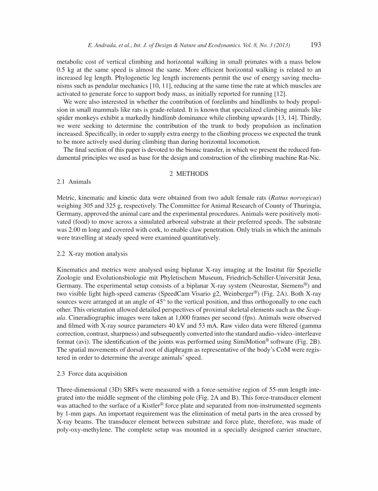
Kinematics and metrics were analysed using biplanar X-ray imaging at the Institut für Spezielle Zoologie und Evolutionsbiologie mit Phyletischem Museum, Friedrich-Schiller-Universität Jena, Germany. The experimental setup consists of a biplanar X-ray system (Neurostar, Siemens®) and two visible light high-speed cameras (SpeedCam Visario g2, Weinberger®) (Fig. 2A). Both X-ray sources were arranged at an angle of 45° to the vertical position, and thus orthogonally to one each other. This orientation allowed detailed perspectives of proximal skeletal elements such as the Scap-ula. Cineradiographic images were taken at 1,000 frames per second (fps). Animals were observed and fi lmed with X-ray source parameters 40 kV and 53 mA. Raw video data were fi ltered (gamma correction, contrast, sharpness) and subsequently converted into the standard audio–video– interleave format (avi). The identifi cation of the joints was performed using SimiMotion® software (Fig. 2B). The spatial movements of dorsal root of diaphragm as representative of the body’s CoM were regis-tered in order to determine the average animals’ speed.
2.3 Force data acquisition
Three-dimensional (3D) SRFs were measured with a force-sensitive region of 55-mm length inte-grated into the middle segment of the climbing pole (Fig. 2A and B). This force-transducer element was attached to the surface of a Kistler® force plate and separated from non-instrumented segments by 1-mm gaps. An important requirement was the elimination of metal parts in the area crossed by X-ray beams. The transducer element between substrate and force plate, therefore, was made of poly-oxy-methylene. The complete setup was mounted in a specially designed carrier structure,
194 E. Andrada, et al., Int. J. of Design & Nature and Ecodynamics. Vol. 8, No. 3 (2013)
which permitted easy adjustment of the support inclination. SRFs were collected at 500 fps. Ana-logue force data were amplifi ed (8-Channel Charge Amplifi er, Type 9865, Kistler®), converted into a digital format via NI USB-6229 (National Instruments®) and recorded with a self-developed tool in LabView® 8.2 (National Instruments®). Force measurements and X-ray analyses were synchro-nized electronically (post-trigger). The forces in the anterior–posterior, medial–lateral and normal directions (respectively, Fap, Fml and Fn) were computed from the amplifi ed signals Sm multiplied by the linear calibration matrix C, which was previously determined from measurements on calibrated loads. This analysis yielded the following values for the uncertainty of the measured forces: ΔFap = ±0.02 N; ΔFml = 0.02 N; ΔFn = 0.04 N.
2.4 Mechanical link model
The mechanical model consists of 20 rigid segments, representing toes, feet (fore- and hindlimbs each), shank, thigh, lower arms, upper arms, scapulae (all together forming the extremities), pelvis, abdomen, thorax and head (trunk). These segments were assumed to move only in the sagittal plane [cf. the results of former studies, e.g. 4–6, 15] and to be linked via pin-joints (Fig. 2C). To calculate inertial properties (i.e. mass, position of centre of mass [CoM], and inertial tensor about the CoM), a female rat cadaver (weight 301.12 g) was dissected. The body stem and each extremity were divided into four segments. The dissected segments were measured and weighed; inertial properties of the body stem were estimated by matching each segment to basic geometrical elements (pelvis and head: trapezoid plates; abdomen and thorax: rectangular plates). This approach following Hanavan due to our own experiences provides comparable results to the before used [15] exact mapping of the outer contour by structured light. Inertia of the extremities was not taken into account
Figure 2: (A) Experimental setup: biplanar X-ray system (Neurostar, Siemens®) and simulated arboreal substrate with a force-sensitive region. (B) A still image from an X-ray movie of a rat walking on the simulated horizontal arboreal substrate. (C) Mechanical link model.
E. Andrada, et al., Int. J. of Design & Nature and Ecodynamics. Vol. 8, No. 3 (2013) 195
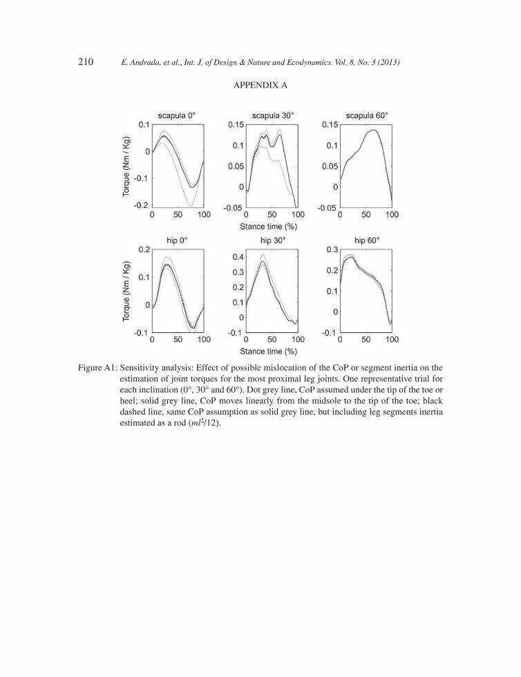
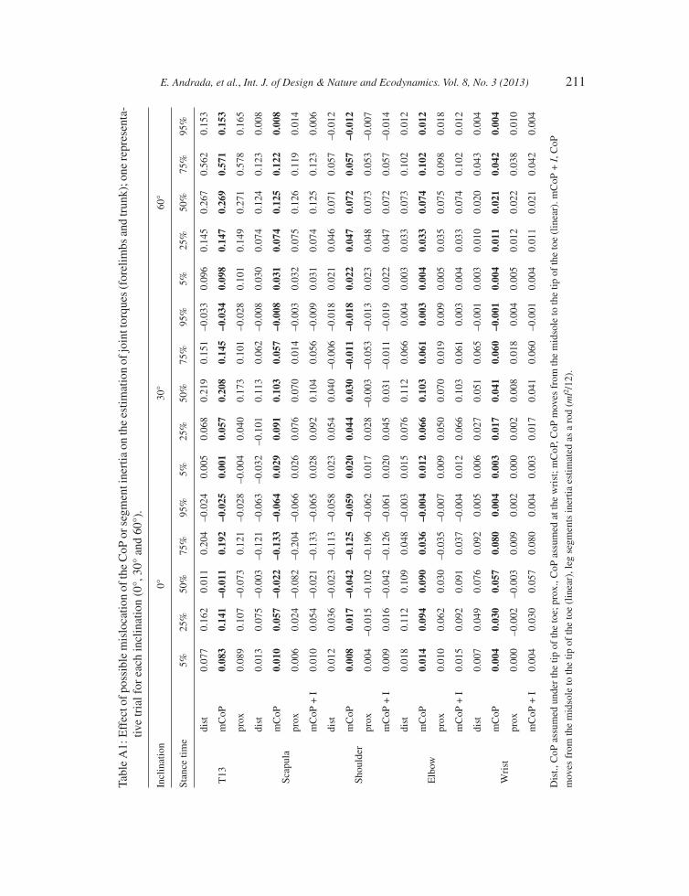
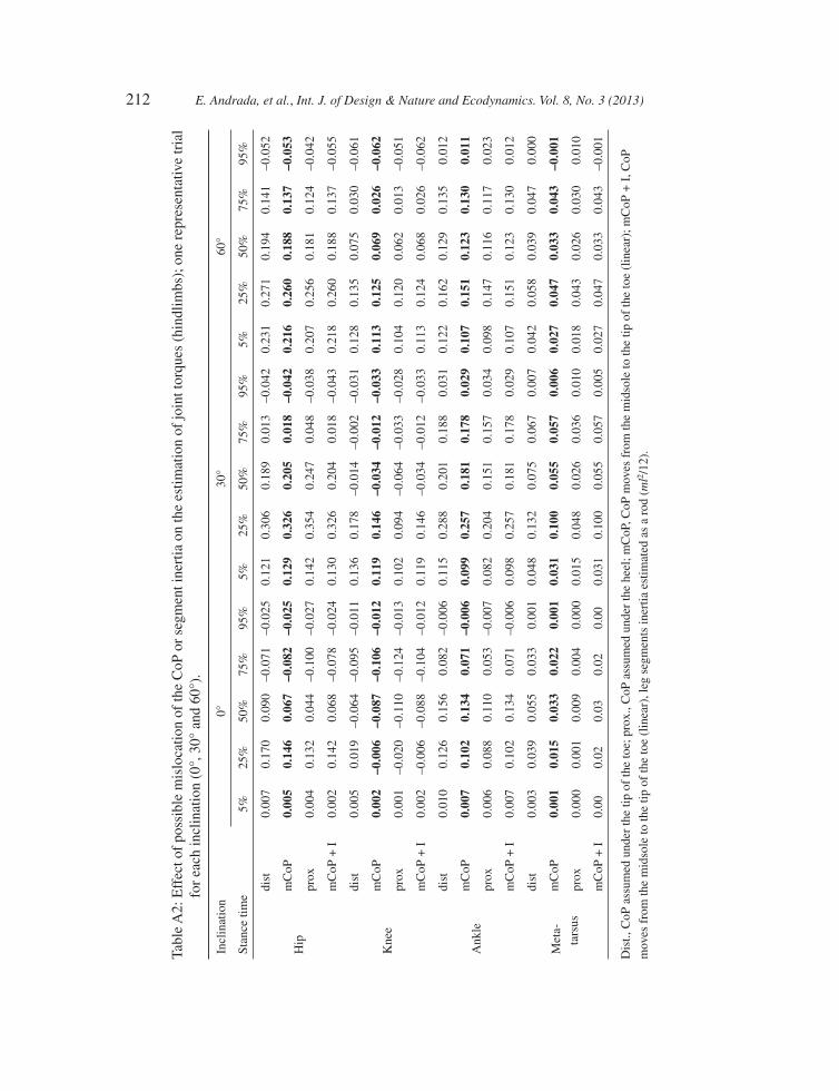
for calculations, since the infl uence of the leg segment inertia, estimated as a thin rod (ml2/12), is <5% of the maximal joint torque, even for the most proximal joints (see Tables A1 and A2 and Fig. A1). The position of CoM for each limb segment was obtained by using a pendulum method as described in [16]. Morphometric parameters are summarized in Table 1. We are aware that a 2-D representation causes especially the abductive and adductive motions of the limbs to be neglected. This simplifi cation has the effect that limb elements that are moved out of plane appear seemingly shorten in a sagittal projection [4], inducing errors in computing forces and torques.
2.5 IDA analysis
On the pole, the centre of pressure (CoP) of the forces acting on the sole of the feet could not be resolved with suffi cient accuracy. We assumed the CoP to be located at the beginning of the stance in the middle of the sole, following [15]. After touch-down we animated the position of the CoP to linearly translate from its initial position to the tip of feet.
To enable synchronization of kinematic and force data and to reduce the noise in the twofold numerical derivation necessary for computing linear and angular accelerations, several techniques proposed in literature were applied (third and fi fth order spline interpolation, moving average and Butterworth fi lters) [15, 17]. The trajectories of the segments’ CoMs were calculated from the joint trajectories in combination with morphometric data. The absolute angle of each segment in space was defi ned between the vectors formed by the motion direction and each segment (distal–proximal direction). Joint angles were obtained from the scalar product of the vectors describing two adjacent segments and expressed in accordance with [5]. Internal forces of the joints and net torques about the CoM of limbs and body-stem segments were estimated applying the Newton–Eulerian approach:
0
0
mI r f
J Mj=
⎡ ⎤ ⎧ ⎫ ⎧ ⎫⎨ ⎬ ⎨ ⎬⎢ ⎥⎣ ⎦ ⎩ ⎭ ⎩ ⎭
&&
&& (1)
Table 1: Morphometric parameters of Rattus norvegicus.
Mass (g) J (g cm²) L (cm) CoM (%)
Foot (forelimb) 0.44 – 1.4 50Lower arm 3.22 – 2.1 45Upper arm 4.72 – 2.4 54Scapula 5.16 – 2.4 50Toes 0.39 – 1.5 50Foot (hindlimb) 1.31 – 1.8 60Shank 9.06 – 4.1 38Thigh 13.26 – 2.9 45Head + neck 27.9 84.6 7.5 39Thorax 60.5 207.8 5.8 50Abdomen 93.2 354.8 6.0 50Pelvis 44.4 98.3 3.9 25
Body mass = 301.12 g, J is the mass moment of inertia about the CoM and L the distance between proximal and distal joint. The position of the CoM is relative to the proximal joint.
196 E. Andrada, et al., Int. J. of Design & Nature and Ecodynamics. Vol. 8, No. 3 (2013)
where m is the segment mass, J the inertial tensor about the CoM, I the identity matrix, r the linear acceleration, j the angular acceleration and f includes gravity and all distal and proximal forces. M includes all torques due to forces and net muscular torques. Joint power was estimated as joint torque multiplied by joint angular velocity. Positive power is defi ned as ‘concentric work’ of a mus-cle group (torque and angular velocity have the same sign), negative power as ‘eccentric work’. As in [15], the Scapula was included in the analysis. The scapular fulcrum was modelled as an instan-taneous centre of rotation (ICR), and the net muscular torque was therefore computed about that centre. One of the challenges of computing torques between structures in the trunk was to decide whether shoulder, scapular (both coupled to the trunk by soft tissues) or both torques should be transmitted to the thoracic segment. We decided to compute the net torques in the thoracic– abdominal joint (T13) from propagation of forces and compare torques transferred from forelimbs with those coming from hindlimbs. Theoretically, they should be equal but opposite in sign. However, they usu-ally differ because of error propagation (an observation confi rmed by personal communication with Ogihara [18]). Torques in T13 joint computed using the sum of shoulder and scapular torques were found to be between 1.7 and 2.3 times larger than those obtained in the same joint computed arising from hindlimb data. On the other hand, when torques generated in scapular or shoulder joint are used, differences were below 30%. Therefore, we decided to use the scapular torque, which is nor-mally the greater one [15]. During in-phase gaits (approximately synchronous touch-down events of both forelimbs and hindlimbs, respectively), torques and power were calculated from the total SRF and the kinematics of the left extremities. In order to obtain the torques and power acting in each joint, the results were be divided by 2, on the assumption that there was equal distribution over the two sides of the body. Before average values were calculated, and to achieve a common time base for normalization in a series of corresponding measurements, each result for torque, angular velocity and power was interpolated and 300 points were obtained. The signal processing, the model and the IDA were all implemented in Matlab®.
2.6 Statistical analyses
Statistical analyses were performed using SPSS® 18 and Graph Prism® 4.0 for Macintosh®. Least-squares regression was used to determine if any statistical relationship existed between speed and each kinematic variable. If no correlation with speed existed, we used two-way analysis of variance (ANOVA; individual and substrate as factors) to examine the effects of different substrate orienta-tions on the kinematic variables. Two-way analysis of covariance (ANCOVA) was used if the variable showed correlation with speed. The Bonferroni post hoc test was used to compare substrate orientations. Signifi cance level was p < 0.05.
For fi nal data analysis, we were able to obtain a total of 44 steady-state strides (16 at 0°, 18 at 30° and 10 at 60°) of biplanar X-ray recording and synchronous, single limb SRF traces. We additionally included 10 (5 forelimb and 5 hindlimb) strides obtained at 60° inclination for the kinematic analy-sis. For our investigation of steady-state locomotion, we discarded all trials with a horizontal speed deviation of more than 5% during stance.
3 RESULTS3.1 Metrics and kinematics
While the animals preferred the walk (symmetrical gait) during horizontal locomotion on the pole, they switched to a more asymmetrical fast walk or grounded running (trot without aerial phases) at 30° of substrate inclination. Pulse climbing (in-phase gait, for a detailed description see [19]) was
E. Andrada, et al., Int. J. of Design & Nature and Ecodynamics. Vol. 8, No. 3 (2013) 197
preferred during locomotion at 60°. Speed decreased signifi cantly with increasing substrate orienta-tion, whereas stance duration of the forelimbs and hindlimbs increased (Table 2).
As shown in Tables 3 and 4, most joint and element angles of the forelimbs differ signifi cantly between horizontal locomotion and locomotion on an incline, in particular at 60° inclination. In the hindlimbs, we observed signifi cant differences between the 30° and 60° inclinations. Contrary to these, differences between horizontal locomotion and locomotion at 30° were only minimal (i.e. only changes in rhythmical contact events of the limbs occur while kinematics is conserved). Trunk joint angles (illio-sacral and T13 joint) displayed signifi cant variation only between locomotion at 30° and 60°.
3.2 Kinetics
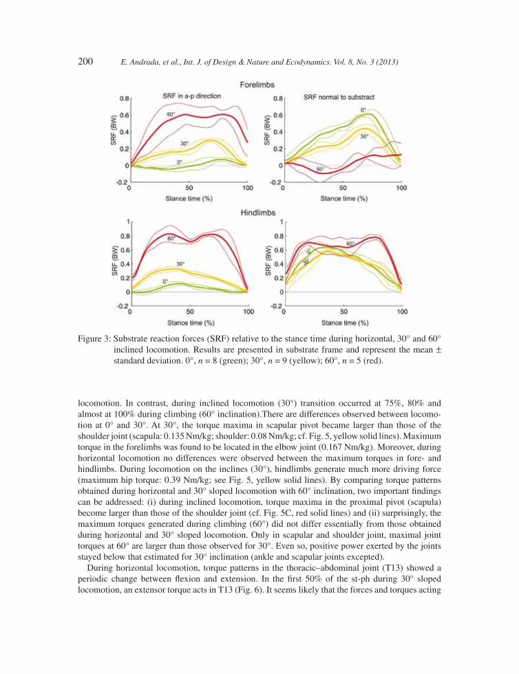
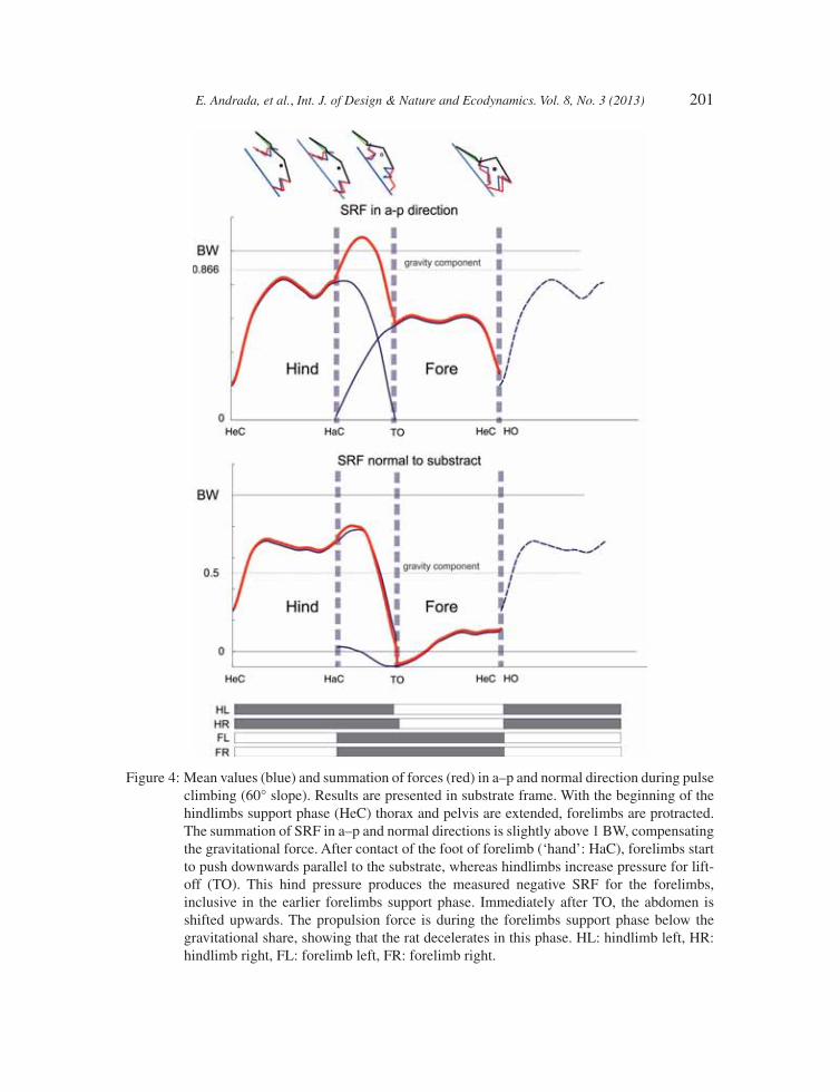
During horizontal locomotion, the normal (vertical) components of the SRF display a half-sine func-tion. Maximal value of the normal force measured for the forelimbs occurs during late stance phase (stance = 70%; SRFn = 0.614 BW (body weight); std = 0.0456 BW), while that of the hindlimb occurs during early stance phase (stance = 30%; SRFn = 0.634 BW; std = 0.0587 BW). The anterior–posterior (a–p) component of SRF for the forelimb displays biphasic behaviour, negative at fi rst, changing to positive at the middle of stance. On the other hand, the a–p SRF component of the hindlimb presents a positive half-sine pattern. With increased inclination, a–p components of the SRF become propulsive (Figs 3 and 4). Comparing the results obtained from 0° and 30° and regard-less of the grade-related offset in the SRF, the shapes of SRF at 0° and 30° inclination are quite similar. At 60°, forces are mainly ruled by gravity. During stance phase of the hindlimbs, the result-ant of SRF in a–p and normal directions is slightly above body weight, thus mainly compensating gravitational force. Shortly after initial contact of the feet of forelimbs (‘hands’: HaC), the forelimbs push downwards parallel to the substrate, whereas hindlimbs increase pressure for lift-off (TO). This enables the forelimbs to pull on the substrate and thus to generate negative SRFs. Immediately after TO, abdomen is shifted upwards (Fig. 4).
3.3 Joint torques and powers
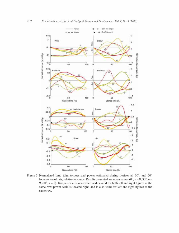
Functionally analogous segments in forelimbs and hindlimbs (i.e. scapula-thigh; upper arm-shank; forearm-foot, for further explanations see [5, 15]) displayed similar torques and power patterns dur-ing horizontal locomotion as well as during locomotion at 30° substrate orientation (power in knee and shoulder joints like for 0° excepted, cf. Fig. 5 knee and shoulder in green dashed lines). During climbing (60° inclination), the shape of the torque graphs changes (i.e. torques in scapular and
Table 2: Mean values (±SD) of speeds and stance durations of forelimbs and hindlimbs during arboreal locomotion at different inclinations (0°, 30° and 60°).
0° 30° 60°
N = 8 N = 9 N = 10
Stance duration (sec) FL 0.13 ± 0.02 0.10 ± 0.01 0.17 ± 0.04Stance duration (sec) HL 0.14 ± 0.03 0.12 ± 0.01 0.20 ± 0.04Speed (m/s) 0.71 ± 0.09 0.83 ± 0.09 0.50 ± 0.09
198 E. Andrada, et al., Int. J. of Design & Nature and Ecodynamics. Vol. 8, No. 3 (2013)
shoulder joints become monophasic, while those in the hip and knee joints remain biphasic; cf. Fig. 5, red solid lines). During horizontal locomotion, hip and scapula exhibited a biphasic torque path (cf. Fig. 5, green solid lines), whereas hip extensors and scapular retractors worked concentri-cally (i.e. ‘generating’ energy) up to 50% of the stance phase (st-ph). During the second part of st-ph, hip fl exors and scapular protractors worked eccentrically (i.e. absorbing energy; cf. Fig. 5, green dashed lines).
Torques and power patterns for knee and shoulder joints revealed asymmetrical biphasic behav-iour (cf. Fig. 5, green solid lines). Of the knee and the shoulder fi rst, the knee joint was concentrically fl exed until approximately 15% of the st-ph (Fig. 5, green dashed line) and the shoulder joint con-centrically retracted until approximately 30% of st-ph (Fig. 5, green dashed line), then the knee joint was eccentrically extended and the shoulder joint concentrically protracted. On the other hand, torque and power curves of ankle and elbow joints were monophasic (plantar and lower arm extensors
Table 3: Mean values (± SD), ANOVAs and ANCOVAs (F-values) of 2D joint angles and element angles of the forelimbs during arboreal locomotion at different inclinations (0°, 30° and 60°).
F-value p-Values
0° 30° 60° 0° vs. 30° 0° vs. 60° 30° vs. 60°
N = 8 N = 9 N = 10 N = 8 N = 9 N = 10
Shoulder joint Td 99 8 112 10 113 12 7.4** 0.003 0.009 n.s.ms 77 5 98 5 103 8 23.1*** <0.001 <0.001 n.s.lo 83 5 95 6 106 10 15.3*** n.s. <0.001 n.s.
Elbow joint td 74 8 84 9 83 13 16.5*** 0.016 <0.001 n.s.ms 72 5 92 7 72 6 9.0** 0.001 n.s. 0.028lo 95 12 109 12 110 16 n.s. n.s. n.s. n.s.
Wrist joint td 157 6 176 6 188 13 n.s. n.s. n.s. n.s.ms 111 5 121 15 166 17 32.1*** n.s. <0.001 <0.001lo 147 17 167 25 163 48 n.s. n.s. n.s. n.s.
Scapula td 37 4 54 8 55 12 5.5* 0.006 0.007 n.s.ms 70 7 96 5 108 9 42.3*** <0.001 <0.001 0.025lo 90 7 110 4 128 2 11.5*** n.s. 0.001 0.5
Upper arm td 62 5 62 6 58 14 n.s. n.s. n.s. n.s.ms 2 5 6 3 –3 8 7.5** n.s. 0.049 0.004lo –15 5 –16 5 –23 11 n.s. n.s. n.s. n.s.
Lower arm td 15 4 23 6 25 9 3.9* n.s. 0.017 n.s.ms 74 6 92 5 76 8 10.3*** 0.001 n.s. 0.003lo 116 10 126 7 133 10 8.3** n.s. 0.001 n.s.
Foot (‘hand’) td 14 6 17 6 38 8 32.1*** n.s. <0.001 <0.001ms 11 4 29 14 58 9 49.8*** 0.002 <0.001 <0.001lo 83 25 121 21 137 17 10.5** 0.007 <0.001 n.s.
Abbreviations: td, touch-down; ms, mid stance; lo, lift-off. Bonferroni post hoc tests (p-values) were used to compare substrate orientations (0°, 30° and 60°).*p < 0.05, **p < 0.01, *** p < 0.001.
E. Andrada, et al., Int. J. of Design & Nature and Ecodynamics. Vol. 8, No. 3 (2013) 199
Table 4: Mean values (SD), ANOVAs and ANCOVAs (F-values) of 2D joint angles and element angles of the hindlimbs during arboreal locomotion at different inclinations (0°, 30° and 60°).
F-value p-Value
0° 30° 60° 0° vs. 30° 0° vs. 60° 30° vs. 60°
N = 8 N = 9 N = 10 N = 8 N = 9 N = 10
Hip joint td 36 5 44 6 53 7 19.2*** n.s. <0.001 0.011ms 62 8 76 6 78 9 15.1*** n.s. <0.001 n.s.lo 101 13 112 9 107 11 n.s. n.s. n.s. n.s.
Knee joint td 82 6 78 9 67 8 8.6** n.s. 0.002 0.029ms 60 7 67 7 61 7 n.s. n.s. n.s. n.s.lo 74 12 100 13 105 16 10.0** n.s. 0.004 n.s.
Ankle joint td 88 8 83 6 76 9 5.3* n.s. 0.011 n.s.ms 63 9 47 5 44 8 12.0*** 0.001 <0.001 n.s.lo 80 10 95 8 99 17 4.8* n.s. 0.019 n.s.
Metatarso-phalangeal joint
td 186 15 167 4 196 9 17.6*** 0.004 n.s. <0.001ms 180 6 181 6 188 9 n.s. n.s. n.s. n.s.lo 175 26 193 25 170 25 n.s. n.s. n.s. n.s.
Pelvis td 31 6 36 6 36 6 4.7* n.s. n.s. n.s.ms 26 7 22 4 22 8 n.s. n.s. n.s. n.s.lo 22 5 9 6 2 4 34.7*** <0.001 <0.001 0.022
Thigh td 6 4 8 6 16 6 8.3** n.s. 0.002 0.021ms 36 5 53 7 54 13 10.5** n.s. 0.001 n.s.lo 80 9 103 8 106 12 14.6*** <0.001 <0.001 n.s.
Lower leg td 76 5 70 2 50 9 39*** n.s. <0.001 <0.001ms 23 4 13 5 8 7 14.9*** 0.006 <0.001 n.s.lo 2 7 –4 7 2 5 n.s. n.s. n.s. n.s.
Metatarsus td 12 7 12 6 23 10 5.8** n.s. 0.021 0.029ms 39 7 33 6 38 5 n.s. n.s. n.s. n.s.lo 88 10 98 8 99 14 n.s. n.s. n.s. n.s.
Abbreviations: td, touch-down; ms, mid stance; lo, lift-off. Bonferroni post hoc tests (p-values) were used to compare substrate orientations (0°, 30° and 60°).*p < 0.05, **p < 0.01, ***p < 0.001.
worked concentrically). Only for the most distal joints, torques and power patterns were found to be different (metatarsophalangeal and wrist joints). Interestingly, the paths of the torque curves for hind limbs during ground locomotion in rats and those obtained from human beings during normal walk-ing seem to be very similar (cf. [17]). If inclination increases, the infl exion point in the biphasic joint torques and power paths in the most proximal joints is gradually shifted towards 100% of st-ph.
By doing this, the relative duration of the positive joint power phase is incremented, resulting in a higher generation of mechanical work. Transition between concentric and eccentric work of the musculature in the most proximal joints occurred at approximately 50% of st-ph during horizontal
200 E. Andrada, et al., Int. J. of Design & Nature and Ecodynamics. Vol. 8, No. 3 (2013)
locomotion. In contrast, during inclined locomotion (30°) transition occurred at 75%, 80% and almost at 100% during climbing (60° inclination).There are differences observed between locomo-tion at 0° and 30°. At 30°, the torque maxima in scapular pivot became larger than those of the shoulder joint (scapula: 0.135 Nm/kg; shoulder: 0.08 Nm/kg; cf. Fig. 5, yellow solid lines). Maximum torque in the forelimbs was found to be located in the elbow joint (0.167 Nm/kg). Moreover, during horizontal locomotion no differences were observed between the maximum torques in fore- and hindlimbs. During locomotion on the inclines (30°), hindlimbs generate much more driving force (maximum hip torque: 0.39 Nm/kg; see Fig. 5, yellow solid lines). By comparing torque patterns obtained during horizontal and 30° sloped locomotion with 60° inclination, two important fi ndings can be addressed: (i) during inclined locomotion, torque maxima in the proximal pivot (scapula) become larger than those of the shoulder joint (cf. Fig. 5C, red solid lines) and (ii) surprisingly, the maximum torques generated during climbing (60°) did not differ essentially from those obtained during horizontal and 30° sloped locomotion. Only in scapular and shoulder joint, maximal joint torques at 60° are larger than those observed for 30°. Even so, positive power exerted by the joints stayed below that estimated for 30° inclination (ankle and scapular joints excepted).
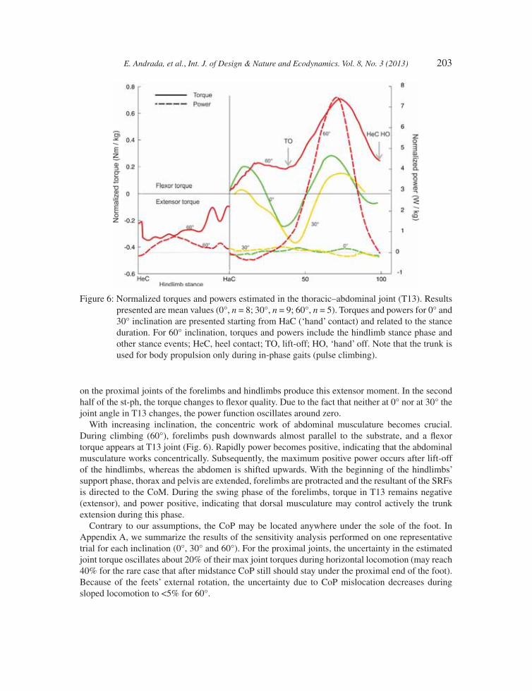
During horizontal locomotion, torque patterns in the thoracic–abdominal joint (T13) showed a periodic change between fl exion and extension. In the fi rst 50% of the st-ph during 30° sloped locomotion, an extensor torque acts in T13 (Fig. 6). It seems likely that the forces and torques acting
Figure 3: Substrate reaction forces (SRF) relative to the stance time during horizontal, 30° and 60° inclined locomotion. Results are presented in substrate frame and represent the mean ± standard deviation. 0°, n = 8 (green); 30°, n = 9 (yellow); 60°, n = 5 (red).
E. Andrada, et al., Int. J. of Design & Nature and Ecodynamics. Vol. 8, No. 3 (2013) 201
Figure 4: Mean values (blue) and summation of forces (red) in a–p and normal direction during pulse climbing (60° slope). Results are presented in substrate frame. With the beginning of the hi ndlimbs support phase (HeC) thorax and pelvis are extended, forelimbs are protracted. The summation of SRF in a–p and normal directions is slightly above 1 BW, compensating the gravitational force. After contact of the foot of forelimb (‘hand’: HaC), forelimbs start to push downwards parallel to the substrate, whereas hindlimbs increase pressure for lift-off (TO). This hind pressure produces the measured negative SRF for the forelimbs, inclusive in the earlier forelimbs support phase. Immediately after TO, the abdomen is shifted upwards. The propulsion force is during the forelimbs support phase below the gravitational share, showing that the rat decelerates in this phase. HL: hindlimb left, HR: hindlimb right, FL: forelimb left, FR: forelimb right.
202 E. Andrada, et al., Int. J. of Design & Nature and Ecodynamics. Vol. 8, No. 3 (2013)
Figure 5: Normalized limb joint torques and power estimated during horizontal, 30°, and 60° locomotion of rats, relative to stance. Results presented are mean values (0°, n = 8; 30°, n = 9; 60°, n = 5). Torque scale is located left and is valid for both left and right fi gures at the same row, power scale is located right, and is also valid for left and right fi gures at the same row.
E. Andrada, et al., Int. J. of Design & Nature and Ecodynamics. Vol. 8, No. 3 (2013) 203
on the proximal joints of the forelimbs and hindlimbs produce this extensor moment. In the second half of the st-ph, the torque changes to fl exor quality. Due to the fact that neither at 0° nor at 30° the joint angle in T13 changes, the power function oscillates around zero.
With increasing inclination, the concentric work of abdominal musculature becomes crucial. During climbing (60°), forelimbs push downwards almost parallel to the substrate, and a fl exor torque appears at T13 joint (Fig. 6). Rapidly power becomes positive, indicating that the abdominal musculature works concentrically. Subsequently, the maximum positive power occurs after lift-off of the hindlimbs, whereas the abdomen is shifted upwards. With the beginning of the hindlimbs’ support phase, thorax and pelvis are extended, forelimbs are protracted and the resultant of the SRFs is directed to the CoM. During the swing phase of the forelimbs, torque in T13 remains negative (extensor), and power positive, indicating that dorsal musculature may control actively the trunk extension during this phase.
Contrary to our assumptions, the CoP may be located anywhere under the sole of the foot. In Appendix A, we summarize the results of the sensitivity analysis performed on one representative trial for each inclination (0°, 30° and 60°). For the proximal joints, the uncertainty in the estimated joint torque oscillates about 20% of their max joint torques during horizontal locomotion (may reach 40% for the rare case that after midstance CoP still should stay under the proximal end of the foot). Because of the feets’ external rotation, the uncertainty due to CoP mislocation decreases during sloped locomotion to <5% for 60°.
Figure 6: Normalized torques and powers estimated in the thoracic–abdominal joint (T13). Results presented are mean values (0°, n = 8; 30°, n = 9; 60°, n = 5). Torques and powers for 0° and 30° inclination are presented starting from HaC (‘hand’ contact) and related to the stance duration. For 60° inclination, torques and powers include the hindlimb stance phase and other stance events; HeC, heel contact; TO, lift-off; HO, ‘hand’ off. Note that the trunk is used for body propulsion only during in-phase gaits (pulse climbing).
204 E. Andrada, et al., Int. J. of Design & Nature and Ecodynamics. Vol. 8, No. 3 (2013)
4 DISCUSSIONThe present study is a logical continuation of previously published studies on locomotion of small therian mammals on fl at ground [4–6, 15, 20]. For the fi rst time, reaction forces, limbs and trunk torques and power paths of rats during simulated arboreal locomotion are presented here.
4.1 Gait modes and kinematics
Our fi rst question was whether gait modes, temporal gait parameters and, therefore, joint kinematics and kinetics are grade-related. Rats display two different climbing strategies in dependence of the slope angle. During horizontal locomotion, rats prefer symmetrical gaits, at 30° they use a less sym-metrical gait (fast walk or grounded running). At 60° inclination, rats switch to a quasi-static synchronous gait (‘pulse climbing’). Our fi ndings show that there are minor grade-related changes in joint and element angles kinematics of the hindlimbs when comparing horizontal with 30° inclined locomotion. At 30° inclination, joint torques and joint angular velocity increase in order to increase joint power.
4.2 Pole and slope-related kinetics
Animals moving on narrow branches typically reduce both vertical and a–p forces [e.g. 21, 22]. Our results add to that observation when compared with data published in earlier works on fl at terrain and poles [e.g. 23–25]. This reduction increases if the diameter of the pole decreases [25]. Peak reduction of SRF is normally attributed to a more fl exed and compliant limb [22]. Fast locomotion combined with compliant limbs normally leads to grounded running. This gait, which is character-ized by duty factors linked to walking (duty factor >0.5) and running-like energy fl uctuations of the body, offers some advantages for pole locomotion like increased step lengths and reduced vertical excursions of the CoM [26].
Our second question asked whether the contribution of forelimbs and hindlimbs to body propul-sion in rats is grade-related. In this respect, our results show grade-related dependencies, which can be summarized as follows: During horizontal locomotion, both extremities contribute almost in the same way to body support. As observed previously in other mammals, forelimbs generate larger braking forces [13]. During arboreal locomotion on an incline, the locomotion of rats becomes markedly ‘hindlimb dominated’, as observed in primate quadrupedal locomotion [cf. 13]. As stated in [27], the more inclined the substrate, the more is the part of the weight to be borne by the limbs positioned closer to the ground. Simultaneously, the component of the weight force parallel to the substrate increases as a function of the sine of the slope angle. This component is usually balanced by friction (Coulomb). Friction is proportional to the force exerted. It follows that it is easier to generate the force necessary to push the CoM upwards by means of the hind limbs (carrying a greater portion of the weight) than to pull it by the forelimbs with their disadvantageous lever arm (cf. [28]).
4.3 Slope-related joint torques and powers
Net limb joint torques in quadrupedal mammals generally refl ect the need to counteract gravity [15, 29]. The ‘anti-gravity role’ of limb joint extensors torques prevents gravity induced limb collapse during weight bearing [e.g. 30, 31]. On the pole, this basic principle does not change, thus our net limb joint torques’ results during horizontal locomotion on the pole agreed with data published in earlier works on fl at terrain [e.g. 15, 32, 33].
E. Andrada, et al., Int. J. of Design & Nature and Ecodynamics. Vol. 8, No. 3 (2013) 205
This study shows, moreover, that during horizontal locomotion, torques and power for the most proximal joints in forelimbs are very much akin to those displayed by the hind limbs (maximum value and shape). Our hypothesis is that this is due to similar (conservative) neuronal activation paths for both limb pairs. In addition, the most proximal joints tend to contribute more to the actua-tion; these differences become even more obvious as inclination increases. On the other hand, the distal joints like ankle and wrist seem to be the most important contributors to spring-like behaviour and terrain adaptation (ankle extensors and their long tendons provide an obvious site for the storage and release of mechanical energy [34]). Moreover, our results show the importance of the ankle’s contribution to lift-off events at 60° inclination.
If one represents the complete st-ph of a rat during grounded running in terms of motions of its CoM, the whole behaviour could also be represented as a spring–mass system [35]. Our results show, contrary to our assumptions, that this response seems to be mainly produced due to the spring-like behaviour of the extremities. Our fi ndings indicate that no energy exchange may occur inside the rat’s trunk during walk or grounded running.
Surprisingly, maximal joint torques during walking and climbing did not differ signifi cantly. Fur-thermore, torques obtained at 60° inclination were lower than those obtained at 30°. We deduce that between 30° and 60° rats may reach the maximal joint torques they can exert, especially in the hind limbs. Thus, in order to climb more sloped substrates, as observed at 60°, they may have to switch to a more quasi-static in-phase gait, which permits them to exert the necessary propulsional force using similar limb joint torques. To that purpose, the active co-work of the extremities with the trunk becomes crucial. Our results indicate that during forelimb st-ph the concentric work of the abdomi-nal musculature contributes to propulsion. In similar manner, during the swing phase of the forelimbs, concentric work of the dorsal muscles contributes to propulsion. Thus, the fl exion of the trunk helps to swing the hindlimbs forward, whereas trunk extension helps forelimbs in the same way. At the same time, trunk alternate movements increase total kinetic energy, as they increase the energy due to the rotation of the individual parts moving relative to each other. As presented by Alexander [36], the total kinetic energy may be regarded as the sum of two main components: the external kinetic energy (EKE) due to motion of the centre of mass and the internal kinetic energy (IKE) due to rota-tion of parts of the body relative to the centre of mass. The latter can be divided into two components: IKE(a) representing energy due to the rotation of the system as a whole and IKE(b) representing the energy due to the rotation of individual segments. In our case IKE(b) = IKE(bl) + IKE(bt). IKE(bl) represents the energy exerted by the alternate rotation of the legs relative to the trunk, present at 0°, 30° and 60°. IKE(bt) represents the energy due to alternate bending of the trunk (i.e. produced by the relative rotational acceleration between abdomen and thorax), only present at 60° during in-phase gaits. Thus, if IKE(bt) is increased by using trunk fl exion–extension, IKE(bl) due to the alternate rotation of the limbs relative to the trunk can be kept constant or diminished. Thus, limb joint torques or limb joint angular velocity or both could be kept constant or diminished.
We expected a grade-related active work of the trunk as a way to supply extra energy to the climb-ing process. Our fi ndings show, however, that the trunk sagittal bending is used actively only during in-phase gaits, that is not directly as a function of slope, as already observed in previous studies on locomotion of small therian mammals on fl at substrates [5, 15, 20].
Finally, although the change from a symmetrical to a more asymmetrical gait, as observed during locomotion at 30°, may indicate a change in the control program, the gait switching to a more quasi-static in-phase gait seems to be the indication for a change from a grounded to a climbing gait. Rats switch from dynamic grounded gaits to quasi-static behaviour during climbing, perhaps because of a limit of muscular force they can or have to choose to exert. But also because in-phase gaits permit them to perform a task division between fore- and hindlimbs, while hindlimbs support
206 E. Andrada, et al., Int. J. of Design & Nature and Ecodynamics. Vol. 8, No. 3 (2013)
and accelerate body mass, forelimbs only need to balance, and may thus be freed for other tasks, such as investigating, and manipulating objects or food intake [27].
5 BIOLOGICALLY INSPIRED CLIMBING ROBOTBionic transfer does not mean copy from nature, but to synthesize main principles in a technical product. Small mammals are complex structures having many degrees of freedom (DoF) and actua-tion possibilities. For the design of a climbing robot, the reduction of complexity is necessary. In our opinion, the overall degree of freedom has to be reduced for a better understanding of the climbing process and in order to reduce design and control complexity of a robot. In our biomechanical analyses, we observed that when rats climb, their locomotion becomes dominated by hind limbs, and the generation of motion is mainly caused by the trunk and by the proximal muscles of the limbs. Based on our fi ndings, following points were proposed for the design process of a ‘pure’ climbing robot:
1. A quasi-static motion is adequate for climbing at steeper inclinations.2. For pulse climbing, the complex 3D motion can be reduced to a planar motion.3. The motion can be generated in the centre of robot and does not need to be mainly produced in
extremity-like parts.4. For pulse climbing, fore- and hindlimbs can be reduced to grippers. 5. Elastic elements should be integrated in the trunk to store energy and to support the actuators
during climbing.
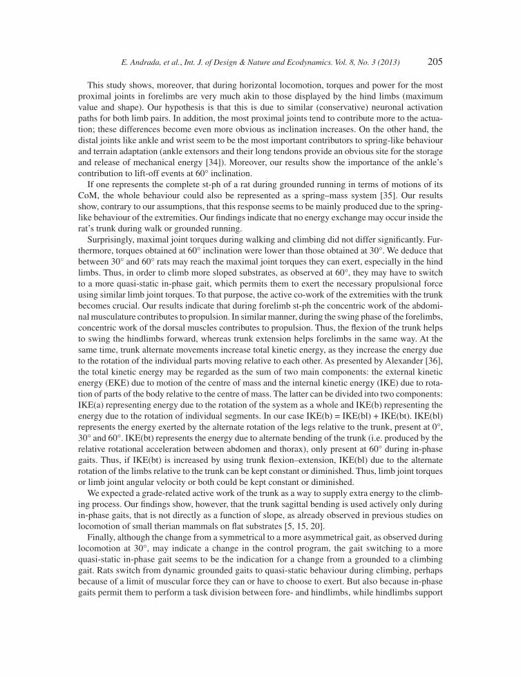
Our climbing robot (Fig. 7) was designed and constructed with a DoF of 4 plus two additional DoF for the grippers. The two hind and two forelimbs were reduced in each case to a gripper. The relative motion between the two grippers is achieved by an actuated linkage mechanism. The frontal
Figure 7: ‘Rat-Nic’ robot – the system basically consists of a smaller front body with gripper and a bigger hind body with gripper, supply unit and electronics. These bodies are connected by a fl exible spine. The actuators are placed in the hind body and the forces are transmitted via Bowden cables.
E. Andrada, et al., Int. J. of Design & Nature and Ecodynamics. Vol. 8, No. 3 (2013) 207
body carries the actuator for the front gripper (and sensor elements); the hind body carries the actua-tors for the spine as well as all necessary electronic components. Due to the observed hind limb dominance during climbing at 60° inclination, and to freed the front body for other tasks, most of the robot mass was concentrated in the hind body. The relative distribution is about 30% in the front and 70% in the hind body. Cyclic locomotion is manly generated by the trunk. In addition, trunk and spine were designed to be compliant, aiming on three main points:
1. To avoid internal mechanical stress by undetermined displacements between front and hind body. During climbing on irregular substrates, front and hind body may be, e.g. laterally dis-placed relatively to each other. Solid constructions with only a limited DoF would be stressed internally avoiding self-aligning of the grippers on the gripped structures.
2. Energy saving. Elastic and spring-like components allow the storage of potential energy. Energy stored in the spring when the light front body is moved upwards is released afterwards to sup-port the motor during the movement of the heavier hind body.
3. Robustness. The elastic nature of the robot leads to a robust system, which can endure fall-downs without damage.
ACKNOWLEDGEMENTSThis work was supported by grant 01RI0633 of the German Federal Ministry of Education (BMBF) under project supervision of DLR-PT. We thank John Nyakatura for providing helpful critique on early drafts of the manuscript, Robert Fetter and Mike Stubenrauch for technical and MTA for experimental support.
REFERENCES[1] Mämpel, J., Andrada, E., Witte, H., Trommer, C., Karguth, A., Fischer, M.S., Voigt, D. &
Gorb, S., Inspirat – Towards a biologically inspired climbing robot for the inspection of linear structures. Proceedings of the Eleventh International Conference on Climbing and Walking Robots and the Support Technologies for Mobile Machines. Advances in Mobile Robotics, pp. 206–213, 2008.
[2] Inspirat project, www.inspirat.de, resp. Witte H., Fischer M.S., Karguth A. & Mämpel J., Abschlussbericht des BMBF-Projektes Inspirat. Berichte aus der Biomechatronik, ed. H.Witte, Ilmenauer Universitätsverlag: Ilmenau, in press.
[3] Andrada, E., Mämpel, J., Schmidt, A., Fischer, M.S., Karguth, A. & Witte H., Biomechanical analyses of rat locomotion during walking and climbing as a base for the design and construc-tion of climbing robots. Design & Nature V: Comparing Design in Nature With Science and Engineering, ed. C. A. Brebbia & A. Carpi, WIT press: Southampton, pp. 165–177, 2010.
[4] Fischer, M.S. & Lehmann R., Application of cineradiography for the metric and kinematic study of in-phase gaits during locomotion of the pika. Zoology, 101, pp. 12–37, 1998.
[5] Fischer, M.S., Schilling, N., Schmidt, M., Haarhaus, D. & Witte H., Basic limb kinematics of small therian mammals. Journal of Experimental Biology, 205, pp. 1315–1338, 2002.
[6] Hackert, R., Schilling, N. & Fischer, M.S., Mechanical self-stabilization, a working hypothesis for the study of evolution of body proportions in terrestrial mammals? Comptes Rendus Paleo-vol, 5, pp. 541–549, 2006. doi: http://dx.doi.org/10.1016/j.crpv.2005.10.010
[7] Eaton, M.D., Evans, D.L., Hodgson, D.R. & Rose, R.J., Effect of treadmill incline and speed on metabolic rate during exercise in Thoroughbred horses. Journal of Applied Physiology, 79, pp. 951–957, 1995.
208 E. Andrada, et al., Int. J. of Design & Nature and Ecodynamics. Vol. 8, No. 3 (2013)
[8] Farley, C.T. & Emshwiller, M., Effi ciency of uphill locomotion in nocturnal and diurnal lizards. Journal of Experimental Biology, 199, pp. 587–592, 1996.
[9] Hanna, J.B., Schmitt, D. & Griffi n, T.M., The energetic cost of climbing in primates. Science, 320(5288), p. 898, 2008. doi: http://dx.doi.org/10.1126/science.1155504
[10] Cavagna, G.A., Heglund, N.C. & Taylor, C.R., Mechanical work in terrestrial locomotion: two basic mechanisms for minimizing energy expenditure. American Journal of Physiology, 233, pp. 243–261, 1977a.
[11] Cavagna, G.A., Heglund, N.C. & Taylor, C.R., Walking, running and galloping: mechanical similarities between different animals. Scale Effects in Locomotion, ed. T.J. Pedley, Academic Press: London, pp. 111–125, 1977b.
[12] Kram, R. & Taylor, C.R., Energetics of running: a new perspective. Nature, 346, pp. 265–267, 1990. doi: http://dx.doi.org/10.1038/346265a0
[13] Demes, B., Larson, S.G., Stern, J.T., Jr., Jungers, W.L., Biknevicius, A.R. & Schmitt, D., The kinematics of primate quadrupedalism: hindlimb drive reconsidered. Journal of Human Evolu-tion, 26(5-6), pp. 353–374, 1994. doi: http://dx.doi.org/10.1006/jhev.1994.1023
[14] Hirasaki, E., Kumakura, H. & Matano, S., Biomechanical analysis of vertical climbing in the spider monkey and the Japanese macaque. American Journal of Physical Anthropology, 113, pp. 455–472, 2000. doi: http://dx.doi.org/10.1002/1096-8644(200012)113:4<455::AID-AJPA2>3.0.CO;2-C
[15] Witte, H., Biltzinger, J., Hackert, R., Schilling, N., Schmidt, M., Reich, C. & Fischer, M.S., Torque patterns of the limbs of small therian mammals during locomotion on fl at ground. Jour-nal of Experimental Biology, 205, pp. 1339–1353, 2002.
[16] Nyakatura, J.A., Andrada, E., Grimm, N., Weise, H. & Fischer, M.S., Kinematics and center of mass mechanics during terrestrial locomotion in Northern Lapwings (Vanellus vanellus, Charadriiformes). Journal Experimental Zoology A Ecological Genetics and Physiology, 317, pp. 580–594, 2012.
[17] Winter, D.A., Biomechanics and Motor Control of Human Movement, John Wiley & Sons: New York, 1990.
[18] Ogihara, N. Personal communication, 2010. Department of Mechanical Engineering, Keio University, Yokohama, Japan.
[19] Hunt, K.D., Cant, J.G.H., Gebo, D. L., Rose, M.D., Walker, S.E. & Youlatus D., Standardized descriptions of primate locomotor and postural modes. Primates, 37(4), pp. 363–387, 1996. doi: http://dx.doi.org/10.1007/BF02381373
[20] Schilling, N. & Hackert, R., Sagittal spine movements of small therian mammals during asym-metrical gaits. Journal of Experimental Biology, 209, pp. 3925–3939, 2006. doi: http://dx.doi.org/10.1242/jeb.02400
[21] Schmitt, D., Forelimb mechanics as a function of substrate type during quadrupedalism in two anthropoid primates. Journal of Human Evolution, 26, pp. 441–457, 1994. doi: http://dx.doi.org/10.1006/jhev.1994.1027
[22] Lammers, A.R. & Biknevicius, A.R., The biodynamics of arboreal locomotion: the effects of substrate diameter on locomotor kinetics in the gray shorttailed opossum (Monodelphis domestica). Journal of Experimental Biology, 207, pp. 4325–4336, 2004. doi: http://dx.doi.org/10.1242/jeb.01231
[23] Clarke, K.A., Differential fore-and hindpaw force transmission in the walking rat. Physiology & Behavior, 58, pp. 415–419, 1995. doi: http://dx.doi.org/10.1016/0031-9384(95)00072-Q
[24] Clarke, K.A., Smart, L. & Still, J., Ground reaction force and spatiotemporal measurements of the gait of the mouse. Behavior Research Methods, Instruments & Computers, 33(3), pp. 422–426, 2001. doi: http://dx.doi.org/10.3758/BF03195396
E. Andrada, et al., Int. J. of Design & Nature and Ecodynamics. Vol. 8, No. 3 (2013) 209
[25] Schmidt, A. & Fischer, M.S., Arboreal locomotion in rats – the challenge of maintaining stability. Journal of Experimental Biology, 213, pp. 3615–3624, 2010. doi: http://dx.doi.org/10.1242/jeb.045278
[26] Andrada, E., Nyakatura, J.A., Müller, R., Rode, C. & Blickhan, R., Grounded running: An overlooked strategy for robots. Autonomous Mobile Systems 2012, Springer: Berlin Heidelberg, pp. 79–87, 2012. doi: http://dx.doi.org/10.1007/978-3-642-32217-4_9
[27] Preuschoft, H., Mechanisms for the acquisition of habitual bipedality: are there biome-chanical reasons for the acquisition of upright bipedal posture? Journal of Anatomy, 204(5), pp. 363–384, 2004. doi: http://dx.doi.org/10.1111/j.0021-8782.2004.00303.x
[28] Preuschoft, H., Witte, H. & Fischer, M.S., Locomotion in nocturnal prosimians. Creatures of the Dark: The Nocturnal Prosimians, eds. L. Alterman et al., Plenum Press: New York, pp. 453–472, 1995. doi: http://dx.doi.org/10.1007/978-1-4757-2405-9_27
[29] Nyakatura, J.A. & Andrada, E., A mechanical link model of two-toed sloths: no pendular mechanics during suspensory locomotion. Acta Theriologica, 58(1), pp. 83–93, 2013. doi: http://dx.doi.org/10.1007/s13364-012-0099-4
[30] Cohen, A.H. & Gans, C., Muscle activity in rat locomotion: movement analysis and electromy-ography of the fl exors and extensors of the elbow. Journal of Morphology, 146, pp. 177–196, 1975. doi: http://dx.doi.org/10.1002/jmor.1051460202
[31] Jenkins, P.A. & Weijs, W.A., The functional anatomy of the shoulder in the Virginia opossum (Didelphis virginiana). Journal of Zoology, 188, pp. 379–410, 1979. doi: http://dx.doi.org/10.1111/j.1469-7998.1979.tb03423.x
[32] Fowler, E.G., Gregor, R.J., Hodgson, J.A. & Roy, R.R., Relationship between ankle muscle and joint kinetics during the stance phase of locomotion in the cat. Journal of Biomechanics, 26, pp. 465–483, 1993. doi: http://dx.doi.org/10.1016/0021-9290(93)90010-C
[33] Dogan, S., Manley, P.A., Vanderby, R., Kohles, S.S., Hartman, L.M. & BcBeath, A.A., Canine intersegmental hip joint forces and moments before and after cemented total hip replacement. Journal of Biomechanics, 28, pp. 753–758, 1991.
[34] Lee, D.V., McGuigan, M.P., Yoo, E.H. & Biewener, A.A., Compliance, actuation, and work characteristics of the goat foreleg and hindleg during level, uphill, and downhill running. Jour-nal of Applied Physiology, 104, pp. 130–141, 2008. doi: http://dx.doi.org/10.1152/japplphysiol.01090.2006
[35] Blickhan, R., The spring-mass model for running and hopping. Journal of Biomechanics, 22, pp 1217–1227, 1989. doi: http://dx.doi.org/10.1016/0021-9290(89)90224-8
[36] Alexander, R.McN., Why mammals gallop? American Zoologist, 28, pp. 237–245, 2008.
‘This is a revised version of the paper published in WIT Transactions on Ecology and the Environ-ment, Vol. 138, © 2010 WIT Press, www.witpress.com, ISSN 1743-3541 (on-line), doi:10.2495/DN100151’.
210 E. Andrada, et al., Int. J. of Design & Nature and Ecodynamics. Vol. 8, No. 3 (2013)
APPENDIX A
Figure A1: Sensitivity analysis: Effect of possible mislocation of the CoP or segment inertia on the estimation of joint torques for the most proximal leg joints. One representative trial for each inclination (0°, 30° and 60°). Dot grey line, CoP assumed under the tip of the toe or heel; solid grey line, CoP moves linearly from the midsole to the tip of the toe; black dashed line, same CoP assumption as solid grey line, but including leg segments inertia estimated as a rod (ml2/12).
E. Andrada, et al., Int. J. of Design & Nature and Ecodynamics. Vol. 8, No. 3 (2013) 211
Tabl
e A
1: E
ffec
t of p
ossi
ble
mis
loca
tion
of th
e C
oP o
r seg
men
t ine
rtia
on
the
estim
atio
n of
join
t tor
ques
(for
elim
bs a
nd tr
unk)
; one
repr
esen
ta-
tive
tria
l for
eac
h in
clin
atio
n (0
°, 3
0° a
nd 6
0°).
Incl
inat
ion
0°30
°60
°
Stan
ce ti
me
5%25
%50
%75
%95
%5%
25%
50%
75%
95%
5%25
%50
%75
%95
%
T13
dist
0.07
70.
162
0.01
10.
204
–0.0
240.
005
0.06
80.
219
0.15
1–0
.033
0.09
60.
145
0.26
70.
562
0.15
3
mC
oP0.
083
0.14
1–0
.011
0.19
2–0
.025
0.00
10.
057
0.20
80.
145
–0.0
340.
098
0.14
70.
269
0.57
10.
153
prox
0.08
90.
107
–0.0
730.
121
–0.0
28–0
.004
0.04
00.
173
0.10
1–0
.028
0.10
10.
149
0.27
10.
578
0.16
5
Scap
ula
dist
0.01
30.
075
–0.0
03–0
.121
–0.0
63–0
.032
–0.1
010.
113
0.06
2–0
.008
0.03
00.
074
0.12
40.
123
0.00
8
mC
oP0.
010
0.05
7–0
.022
–0.1
33–0
.064
0.02
90.
091
0.10
30.
057
–0.0
080.
031
0.07
40.
125
0.12
20.
008
prox
0.00
60.
024
–0.0
82–0
.204
–0.0
660.
026
0.07
60.
070
0.01
4–0
.003
0.03
20.
075
0.12
60.
119
0.01
4
mC
oP +
I0.
010
0.05
4–0
.021
–0.1
33–0
.065
0.02
80.
092
0.10
40.
056
–0.0
090.
031
0.07
40.
125
0.12
30.
006
Shou
lder
dist
0.01
20.
036
–0.0
23–0
.113
–0.0
580.
023
0.05
40.
040
–0.0
06–0
.018
0.02
10.
046
0.07
10.
057
–0.0
12
mC
oP0.
008
0.01
7–0
.042
–0.1
25–0
.059
0.02
00.
044
0.03
0–0
.011
–0.0
180.
022
0.04
70.
072
0.05
7–0
.012
prox
0.00
4–0
.015
–0.1
02–0
.196
–0.0
620.
017
0.02
8–0
.003
–0.0
53–0
.013
0.02
30.
048
0.07
30.
053
–0.0
07
mC
oP +
I0.
009
0.01
6–0
.042
–0.1
26–0
.061
0.02
00.
045
0.03
1–0
.011
–0.0
190.
022
0.04
70.
072
0.05
7–0
.014
Elb
ow
dist
0.01
80.
112
0.10
90.
048
–0.0
030.
015
0.07
60.
112
0.06
60.
004
0.00
30.
033
0.07
30.
102
0.01
2
mC
oP0.
014
0.09
40.
090
0.03
6–0
.004
0.01
20.
066
0.10
30.
061
0.00
30.
004
0.03
30.
074
0.10
20.
012
prox
0.01
00.
062
0.03
0–0
.035
–0.0
070.
009
0.05
00.
070
0.01
90.
009
0.00
50.
035
0.07
50.
098
0.01
8
mC
oP +
I0.
015
0.09
20.
091
0.03
7–0
.004
0.01
20.
066
0.10
30.
061
0.00
30.
004
0.03
30.
074
0.10
20.
012
Wri
st
dist
0.00
70.
049
0.07
60.
092
0.00
50.
006
0.02
70.
051
0.06
5–0
.001
0.00
30.
010
0.02
00.
043
0.00
4
mC
oP0.
004
0.03
00.
057
0.08
00.
004
0.00
30.
017
0.04
10.
060
–0.0
010.
004
0.01
10.
021
0.04
20.
004
prox
0.00
0–0
.002
–0.0
030.
009
0.00
20.
000
0.00
20.
008
0.01
80.
004
0.00
50.
012
0.02
20.
038
0.01
0
mC
oP +
I0.
004
0.03
00.
057
0.08
00.
004
0.00
30.
017
0.04
10.
060
–0.0
010.
004
0.01
10.
021
0.04
20.
004
Dis
t., C
oP a
ssum
ed u
nder
the
tip o
f th
e to
e; p
rox.
, CoP
ass
umed
at t
he w
rist
; mC
oP, C
oP m
oves
fro
m th
e m
idso
le to
the
tip o
f th
e to
e (l
inea
r). m
CoP
+ I
, CoP
mov
es f
rom
the
mid
sole
to th
e tip
of
the
toe
(lin
ear)
, leg
seg
men
ts in
ertia
est
imat
ed a
s a
rod
(ml2 /
12).
212 E. Andrada, et al., Int. J. of Design & Nature and Ecodynamics. Vol. 8, No. 3 (2013)
Tabl
e A
2: E
ffec
t of
poss
ible
mis
loca
tion
of th
e C
oP o
r se
gmen
t ine
rtia
on
the
estim
atio
n of
join
t tor
ques
(hi
ndlim
bs);
one
rep
rese
ntat
ive
tria
l fo
r ea
ch in
clin
atio
n (0
°, 3
0° a
nd 6
0°).
Incl
inat
ion
0°30
°60
°
Stan
ce ti
me
5%25
%50
%75
%95
%5%
25%
50%
75%
95%
5%25
%50
%75
%95
%
Hip
dist
0.00
70.
170
0.09
0–0
.071
–0.0
250.
121
0.30
60.
189
0.01
3–0
.042
0.23
10.
271
0.19
40.
141
–0.0
52
mC
oP0.
005
0.14
60.
067
–0.0
82–0
.025
0.12
90.
326
0.20
50.
018
–0.0
420.
216
0.26
00.
188
0.13
7–0
.053
prox
0.00
40.
132
0.04
4–0
.100
–0.0
270.
142
0.35
40.
247
0.04
8–0
.038
0.20
70.
256
0.18
10.
124
–0.0
42
mC
oP +
I0.
002
0.14
20.
068
–0.0
78–0
.024
0.13
00.
326
0.20
40.
018
–0.0
430.
218
0.26
00.
188
0.13
7–0
.055
Kne
e
dist
0.00
50.
019
–0.0
64–0
.095
–0.0
110.
136
0.17
8–0
.014
–0.0
02–0
.031
0.12
80.
135
0.07
50.
030
–0.0
61
mC
oP0.
002
–0.0
06–0
.087
–0.1
06–0
.012
0.11
90.
146
–0.0
34–0
.012
–0.0
330.
113
0.12
50.
069
0.02
6–0
.062
prox
0.00
1–0
.020
–0.1
10–0
.124
–0.0
130.
102
0.09
4–0
.064
–0.0
33–0
.028
0.10
40.
120
0.06
20.
013
–0.0
51
mC
oP +
I0.
002
–0.0
06–0
.088
–0.1
04–0
.012
0.11
90.
146
–0.0
34–0
.012
–0.0
330.
113
0.12
40.
068
0.02
6–0
.062
Ank
le
dist
0.01
00.
126
0.15
60.
082
–0.0
060.
115
0.28
80.
201
0.18
80.
031
0.12
20.
162
0.12
90.
135
0.01
2
mC
oP0.
007
0.10
20.
134
0.07
1–0
.006
0.09
90.
257
0.18
10.
178
0.02
90.
107
0.15
10.
123
0.13
00.
011
prox
0.00
60.
088
0.11
00.
053
–0.0
070.
082
0.20
40.
151
0.15
70.
034
0.09
80.
147
0.11
60.
117
0.02
3
mC
oP +
I0.
007
0.10
20.
134
0.07
1–0
.006
0.09
80.
257
0.18
10.
178
0.02
90.
107
0.15
10.
123
0.13
00.
012
Met
a-
tars
us
dist
0.00
30.
039
0.05
50.
033
0.00
10.
048
0.13
20.
075
0.06
70.
007
0.04
20.
058
0.03
90.
047
0.00
0
mC
oP0.
001
0.01
50.
033
0.02
20.
001
0.03
10.
100
0.05
50.
057
0.00
60.
027
0.04
70.
033
0.04
3–0
.001
prox
0.00
00.
001
0.00
90.
004
0.00
00.
015
0.04
80.
026
0.03
60.
010
0.01
80.
043
0.02
60.
030
0.01
0
mC
oP +
I0.
000.
020.
030.
020.
000.
031
0.10
00.
055
0.05
70.
005
0.02
70.
047
0.03
30.
043
–0.0
01
Dis
t., C
oP a
ssum
ed u
nder
the
tip o
f th
e to
e; p
rox.
, CoP
ass
umed
und
er th
e he
el; m
CoP
, CoP
mov
es f
rom
the
mid
sole
to th
e tip
of
the
toe
(lin
ear)
; mC
oP +
I, C
oP
mov
es f
rom
the
mid
sole
to th
e tip
of
the
toe
(lin
ear)
, leg
seg
men
ts in
ertia
est
imat
ed a
s a
rod
(ml2 /
12).


![Estimation of Quasi-Stiffness and Propulsive Work of the ... · human locomotion biomechanics including anthropomorphic bipedal robots [1,2], lower-limb wearable exoskeletons [3–10],](https://img.pdfslide.us/doc/110x75/5ed490cb3d6f7d64f90680aa/estimation-of-quasi-stiffness-and-propulsive-work-of-the-human-locomotion-biomechanics.jpg)


![Locomotion [2014]](https://img.pdfslide.us/doc/110x75/5564e3eed8b42ad3488b4e94/locomotion-2014.jpg)


![Locomotion [2015]](https://img.pdfslide.us/doc/110x75/55d39c9ebb61ebfd268b46a2/locomotion-2015.jpg)