Embed Size (px)
Citation preview
From Algae to a Functional Food
Travis DallasEric Graves
Joaquin MartinezChristopher McNinch
Ramune Otterson-MeskyteCharu Saini
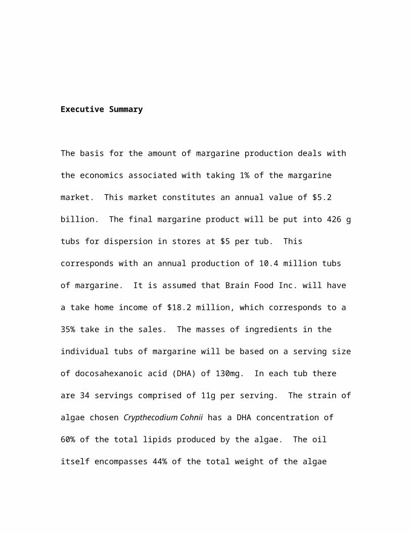
Executive Summary
The basis for the amount of margarine production deals with the economics associated
with taking 1% of the margarine market. This market constitutes an annual value of $5.2
billion. The final margarine product will be put into 426 g tubs for dispersion in stores at
$5 per tub. This corresponds with an annual production of 10.4 million tubs of
margarine. It is assumed that Brain Food Inc. will have a take home income of $18.2
million, which corresponds to a 35% take in the sales. The masses of ingredients in the
individual tubs of margarine will be based on a serving size of docosahexanoic acid
(DHA) of 130mg. In each tub there are 34 servings comprised of 11g per serving. The
strain of algae chosen Crypthecodium Cohnii has a DHA concentration of 60% of the
total lipids produced by the algae. The oil itself encompasses 44% of the total weight of
the algae produced. It is assumed that the final product will have a taste equivalent to any
other margarine on the market due to recipe of ingredients that will be added to each tub.
The cost of the plant required to make this product is approximately $ 44 million, and the
total operations per year is approximately $ 18 million. The plant will begin making
money in its 3rd year and will have a payback period of approximately 11 years.
However, this is based only on a 1 % market share. As the market share of the product
grows, the amount earned per year will increase.
Discussion
Healthy eating is a rapidly growing industry in the 21st century, with more consumers
becoming aware of the need for a balanced and nutritious diet. Omega-3 fatty acids are
becoming a more integral part of this healthy diet. One specifically, docosahexaenoic
acid (DHA) is linked to the healthy development of infants, and the lack of DHA is
affiliated with Alzheimer’s disease. DHA in the past has come from fish oils, but there is
potential for mercury or dioxins contamination as well as a fishy odor and taste.
Recently, it has been found that DHA can be extracted from algae instead of fish oils.
Specific algae strains with high concentrations of DHA can be grown in a controlled
environment and then processed, providing an uncontaminated, highly concentrated, and
completely vegetarian source of DHA. Once extracted, the DHA-rich oils can then be
utilized to create a functional food, such as a healthy margarine. About $5.4 billion
worth of margarines and table spreads are sold every year, however a DHA-fortified
margarine is not currently sold in the United States. As word about the benefits of DHA
spreads, it is apparent that the desire for foods fortified with this omega-3 fatty acid will
grow. A margarine that is fortified in DHA will be both profitable in industry and
beneficial to a public hungry for a healthy diet.
The major negatives for this project mainly come from the projected capital cost of this
plant. The soybean oil that will be used as the main ingredient for the margarine must be
refined to ensure that the final product will contain no trans fatty acids, and the
equipment needed for the refining are quite costly. The ingredients are also very costly,
raising the yearly operating cost associated with the project. Sanitation in a food product
facility is vital. All the equipment must be stainless steel, and each piece of equipment
must be cleaned regularly to ensure the quality and the safety of the product.

Conclusions and Recommendations
The margarine production plant would make 10.5 million tubs of margarine a year. This
facility would being making money in its 4th year, but the payback period for the facility
would not occur until its 11th year. However, this payback period is predicated on a 1 %
share of the margarine market. If the product could increase its market share within the
first few years of production, the payback period could be decreased drastically. If this
project and plant are going to succeed, a strong marketing campaign is necessary. If
marketing cannot sell the product, then it is recommended that the plant not be built.
Appendix 1
Design Basis
The size of all equipment and the economic evaluations are based on a 1 % market share
in the $ 5.2 billion table spread market. This equates to $ 52 million retail. The product
will sell at the market for $ 5, so selling the tubs wholesale will net $ 1.75. In order to
satisfy the 1 % market share, 18.4 million tubs of margarine will be produced every year.
However, much of the equipment is not running at full capacity, making increased
production if the market share increases easy.

Appendix 2
Block Flow Diagram
DegummingBleaching
Removal FFADeodorization
CentrifugeCrude SBO
Citric AcidGumWater
Citric Acid
Citric AcidAcid Activated Clay
EnzymeWater
Acid ActivateClay
Interesterification
Hardfat SBO
Emulsification Pasteurization
WaterSea SaltLecithinDiacetyl
Mono/DiglyceridesB-Carotenes
Sorbic AcidErgocaliferols
Sodium Hydroxide
Citric AcidWater
Sodium HydroxideCitric AcidWater
ScrapedSurface HeatExchanger
Packaging
Refrigerant
To Wholesaler
DissolvedAir
FloatationFermentation CentrifugeCO2
LysingGlucose
Beer StillBottom
Antifoam
Water
Algae
Glucanex
SteamCoolingWater
Sterile air
Vent
Water
Air CO2
LHO-BiomassWater
NaOH
Steam
Steam
Salt
CIPSystem
Block Flow Description
Algae is grown in the fermentation stage, and C. Cohnii is the algae type that will be
grown in the fermentation stage. This species of algae has been chosen because of its
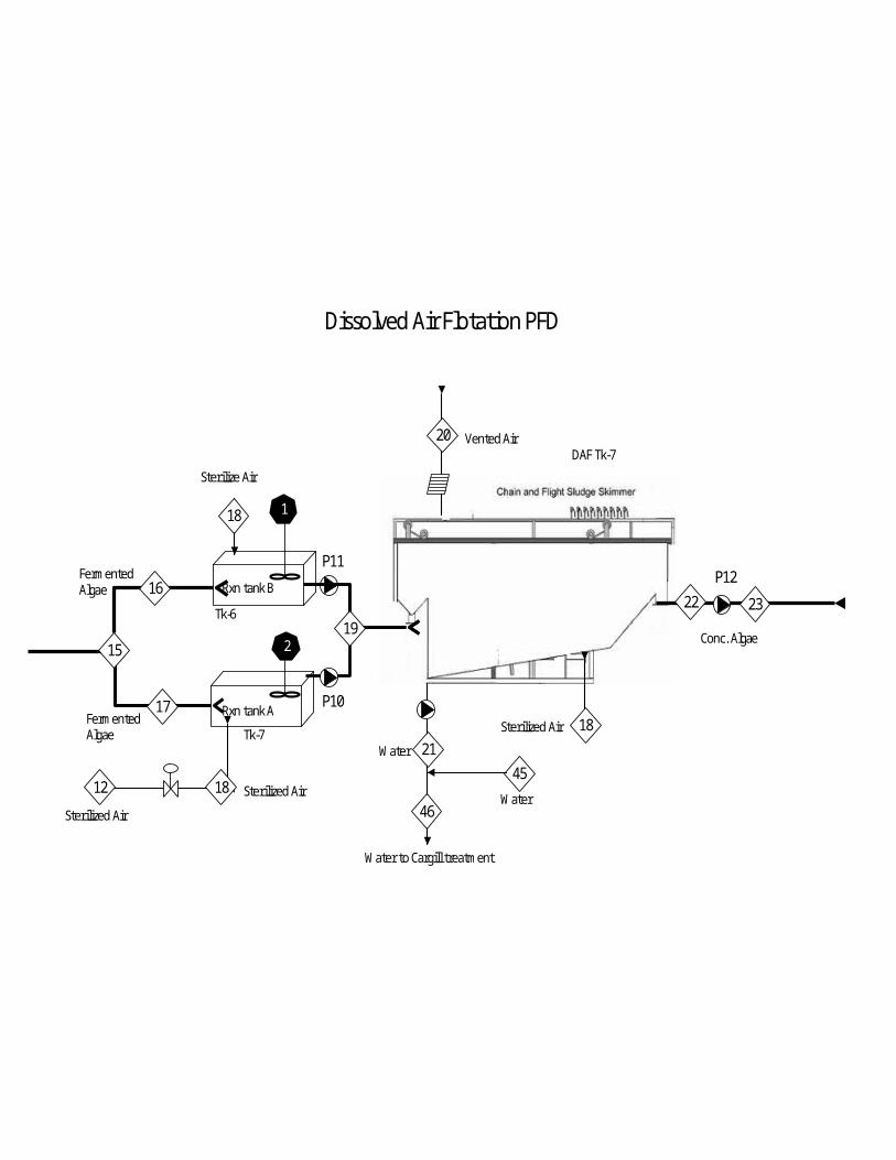
high level of DHA in its lipids. After the algae is grown, the algae bodies are separated
from the liquid using dissolved air floatation. This process uses air to push the algae to
the top of the broth. After the algae is concentrated at the top of the broth, it is separated
from the bulk fluid by a scraper. This next step of the process is cell lysing. This step is
necessary because the DHA is inside the cell and the cell must be broken in order to
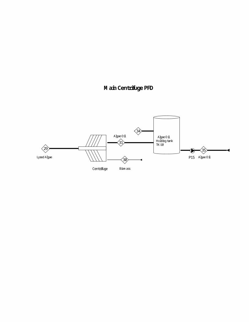
extract the oil. This process uses CO2 to pop open the cells using a pressure differential.
A centrifuge will then separate the oil from the water, leaving the algae oil that will be
used in the margarine process.
The margarine uses refined soybean oil (SBO) that is specially made in a process that
leaves zero trans fatty acids. Crude SBO is bought from Cargill in order to be processed
in our refining plant. The crude SBO is first degummed because the gums contained in
the SBO interfere with the rest of the process. A centrifuge then separates the SBO from
the gums. After the gums are separated, the SBO is bleached and deodorized so that the
final margarine process has a quality taste. Also in this process, free fatty acids are taken
out of the SBO so that the margarine has the correct “mouth feel.” Finally, the last block
of the SBO refining process is interesterification. This is a chemical reaction by which
the glycerides contained in the SBO are randomly reordered in the triglyceride. This
helps the SBO have the right form at the right temperature. If the SBO is too hard, the
margarine would not melt at mouth temperature, creating an unpleasant sensation when
eaten. If the SBO is too soft, then the margarine would liquefy inside the refrigerator,
making it very difficult to spread. The interesterification is used because the more classic
method to create margarine that melts and hardens at the right temperatures utilized
partial hydrogenation. This created trans fatty acids inside the margarine, which are
unhealthy and are avoided in this process.
After these ingredients have been prepared, they are mixed together in the margarine
production process. First the ingredients are emulsified, which is just an intense mixing,
creating a creamy mixture of water suspended within the oil. This resulting emulsion is
then pasteurized in order to ensure that no microbes are still living inside the emulsion.
This is required for a food product so that the consumer is not made ill eating the product.
In the scraped surface heat exchanger, the emulsion is crystallized, after which it is sent
to packaging. All of these systems are cleaned with a clean in place (CIP) system, which
keeps all the equipment clean and free of microbes.
Appendix 3

Process Flow Diagrams
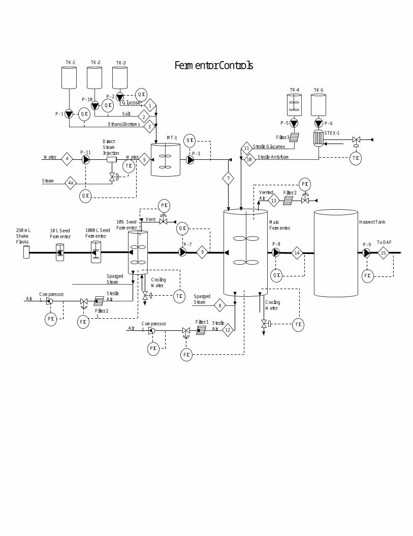
Fermentation PFD
Main Fermenter
Steam Cooling Water
Sparged Steam
Vented Air 13
14
Sterile Air
10% Seed Fermenter
Steam Cooling Water
Sparged Steam
Vent
9
Sterile Air
1000 L Seed Fermenter
10 L Seed Fermenter
250 mL Shake Flasks
Water Water
Direct Steam Injection
MT-1
Salt
Ethanol Bottoms
Glucose
Sterile Glucanex
Sterile Anti-foam
1
2
3
4 5
7
8
11
10
12 Compressor 1
Filter 1 1 Air
Filter 2
TK-1 TK-2 TK-3
TK-4 TK-5
STEX-1
Steam 4a
P- 1 P- 2
P- 3
P- 5 P- 6
P- 7 P- 8
Filter 3 1
To DAF
15
P- 9
Harvest Tank

Rxn tank A
Rxn tank B
P-01
FermentedAlgae
FermentedAlgae Sterilized Air
Sterilize Air
Vented Air
Conc. Algae
Water
45
18
16
15
17
Dissolved Air Flotation PFD
12
Sterilized Air
Sterilized Air18
18
20
19
22 23
21
46Water
1
2
P10
P11P12
Water to Cargill treatment
Tk-6
Tk-7
DAF Tk-7
3
Baffle trayTowerTk- 8
CO2 Lysing PFD
Conc. Algae
Sterilized CO2
CO2 AbsorbedAlgae
LysedAlgae&CO2
Vented CO2
LysedAlgae
Throttle Valve
23
28
24
Filter 2
CO 2
Compressor 2
25 26
27
Stir tank
P13
P14
29
Lysed Algae TowerTk- 9

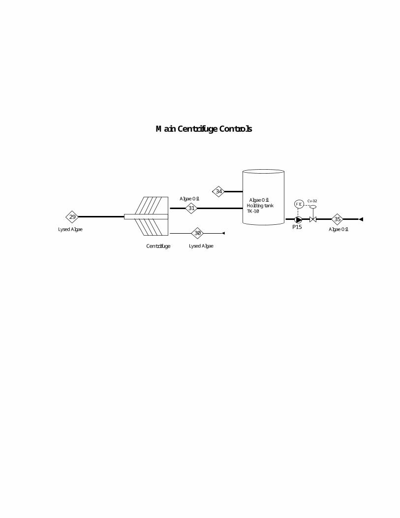
Main Centrifuge PFD
Centrifuge
Lysed Algae
Biomass
Algae Oil
2931
30
Algae Oil Holding tankTK-10
34
P15
35
Algae Oil

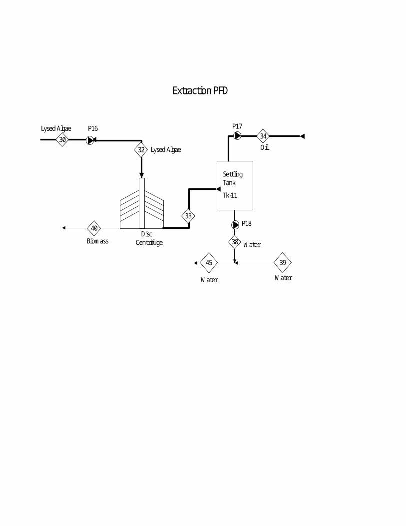
Extraction PFD
Oil
Settling Tank
Tk-11
Water
33
Disc Centrifuge
Lysed Algae P16
40
30 34
38
32 Lysed Algae
Biomass
39
P18
P17
Water
45
Water
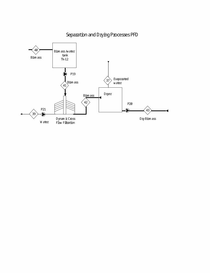
Separation and Drying Processes PFD
Dryer
42
Dynamic Cross Flow Filtration
Biomass
P19
39
40
43
Biomass /water tank
Tk-12
WaterDry Biomass
P20
37 Evaporated water
41Biomass
Biomass
P21

TK- 01Crude SBO
Storage
P-015 4
32
N2 Gas
1
6
TK-0245% Citric
Acid Storage
P-02
7
8
9
10
P-03 P-04 P-05
TK-034% NaOHStorage
TK-04Water
Storage
TK-0510% EnzymeRefrigerated
Storage
12 11
13
14
N2 Gas
CoolingHeating
23 22
15 16
HLO - Gums19
TK-06Batch
Reactor
P-06 P-07
TK-07SurgeTank
20
24
N2 GasTK-08
DegummedSBO
StorageHeating
HX-1
HX-3LLO
21
18 17
HX-2
Cent-01
Degumming PFD
24
N2 Gas
TK-08Degummed
SBOStorage
28 27
HX-4
25 26
TK-0950% Citric
AcidStorage
29
P-08
P-09
30
TK-10Acid
ActivatedClay Tank
32
31
P-10
33
P-11
TK-11Water
Storage
34
35
36
3837
P-12HX-5
4039
P-13
VP-1
TK-12Mixer
4241
43
N2 Gas
TK-13SurgeTank
44
P-14
45
4748
46
MX-2MX-1
49
VP-2
50
51
52
53
54
Steam
55
5657
58
To MX-1
P-15
59
60
6263
64
N2 Gas
61
TK-14Refined
SBOStorage
HX-6
HX-7
HX-8
HX-9
Filter
VacuumVessel
3837
Refining PFD
64
N2 Gas
TK-14Refined
SBOStorage
65
N2 Gas
TK-15SBO
HardfatStorage
67
N2 Gas
TK-16SBO
HardfatHeating
Tank
66
6869
70
74
73 72
77 76
71
75
P-17
P-18
HX-10
HX-11
78
VP-3
7980
81
P-19
TK-17CH3ONaStorage
82
TK-19MixingTank
P-20
85P-21
Filter
86
8990
87 88
91
92 93
94
TK-20Soft
WaterStorage
HX-12
HLO
P-22
P-23 P-24
95 HLO96
Cent-03Cent-02
TK-1820% Citric
AcidStorage
TK-21Dryer
9798
P-252A 1A
99 00
3A
N2 Gas
TK-22SBO
Storage84
83
HX-13
MX-3 MX-4
WaterSoftener
Interesterification PFD
E
Algae OilStorage
Refined SBO Storage
LecithinStorage
Beta CaroteneStorage
DiacetylStorage
SorbicAcidStorage
Mono- diglyceridesStorage
Ergo-califerolStorage
WaterStorage
Oil
Pasteurization
CIP
Warm Water
Aqueous PhasePrep.69
TK-20
TK-21
TK-22
TK-23
CIPCIP
TK-24
TK-25
TK-26
TK-27
TK-30
TK-32
TK-31
Oil Phase Prep.Tank 1
CIP
P-30
P-31
P-32
P-33
Warm Water
Oil Oil Phase Prep.Tank 1
CIP
68
70
67
66
65
64
62 63
60 61
71Sea SaltStorage
TK-29
P-34
73
74
TK-28
75
72
72
76
CIP
79
77
75
79
77
80
Margarine PFD 1
Warm Water
78
P-35
P-35
78
High Pressure Pump
AmmoniaCompressor
Pin Rotor MachineScraped
Surface Heat Exchanger
Packaging
P-37
CIP
80
84
8586
CIP
87
89
90
Margarine PFD 2
83
88
Plate HX
8182
P-36

TK-41Acidic Solution
TK-42Alkaline Solution
TK-43Reclaim Water
TK-44FreshWater
Alkaline Storage
Acidic Storage
CIP Returning Liquid
Water
HX-41
CIP Supplying Liquid
Drain
P-41
P-42
PP
213
203201
216215 207
205
217
212
204202
214
218208206
211
210
209
Strainer
CIP PFD
Process Flow Description

Fermentation
The fermentation of Crypthecodinium cohnii takes place at an ideal temperature of 81°F.
The fermentation process was chosen to be a batch process over a fed-batch process or a
continuous process. The fed-batch process showed no significant benefit to a batch
process, using a glucose substrate, either in final cell density or in fermentation time.
This is likely due to the loss of an unknown growth factor in the ethanol bottoms nutrient
during sterilization. Continuous processes for algae fermentation are untested and can
potentially compromise the sterility of the fermentation. The batch fermentations are to
take place in 35,000 gallon fermentors. Four of these fermentors, operating at 60%
volume capacity, are required to achieve the amount of lipid products specified in our
economic basis.
The fermentation is to take place on a carbon substrate of glucose. Glucose was chosen as
the substrate over acetic acid and ethanol, which could have attained higher cell
concentrations. However, higher concentrations of acetic acid or ethanol are required to
conduct such a fermentation, and both substrates have corrosive qualities that would
cause damage to the fermentors over time. The time period required for acetic acid
fermentations is also longer, at 400 hours, compared to 71 hours per fermentation with
glucose substrate. Ethanol is a fire hazard, especially at the high concentrations required
to ferment C. cohnii.

The fermentation of C. cohnii requires a nitrogen source. The nitrogen source for this
fermentation comes from the dead yeast that collects at the bottoms of ethanol stills.
These ethanol bottoms will act as the nitrogen source and the source of any growth
factors that are not included in other feed components. The concentration of ethanol
bottoms used will be limited to 8-10% of the concentration of glucose used as it is
important that nitrogen be consumed by the end of the growth phase of our C. cohnii.
The lack of a nitrogen source will cause the algae to enter a stationary phase in which
growth no longer occurs, but the algae begin to produce excess lipids.
The growth phase of our algae fermentation was calculated using the Arrhenius equation,
, and was calculated to be 70.15 hours. The growth rate used was calculated
from data taken from de Swaaf, et al, 1998 and was found to be 0.0371 h-1. The
maximum final concentration of algae was found to be 27.7 g dw/l and was assumed to
be 27.0 for the purposes of our fermentor. The stationary phase was assumed from
literature to be optimal at 20 hours. The lipid concentration resulting from the combined
90.15 hour fermentation time was taken to be 5.54 g/l. The fermentation schedule
accounts for a 12 hour maintenance period after each batch, which can be reduced to
increase productivity.
At 60% capacity, a single fermentor will hold 79,500 liters of fluid volume. That volume
will produce 971 pounds of lipids and 4,855 pounds of algae biomass per batch. Each
fermentation will require 7.02 short tons of glucose, 0.65 short tons of ethanol bottoms,
and 2.19 tons of sea salt to achieve a salinity of 25 g/l. The glucose, ethanol bottoms, and
sea salt will be mixed with 60,617 liters of water, in a 27,000 liter tank at 140°F prior to
their transfer to the fermentor. Sterilization takes place in the fermentor using sparged
steam until the broth reaches 250°F and is held at that temperature for 1 hour. The
volume of sparged steam required is 15,926 pounds of steam at 293 °F and 3 barg. The
broth is then cooled with cooling water until the temperature reaches 81°F. A seed batch
of broth, fermented in a 10% seed fermentor, is then added to the main fermentor.
During the fermentation we will add 350 pounds of glucanex and 31 pounds of silicone
anti-foam per batch as needed.
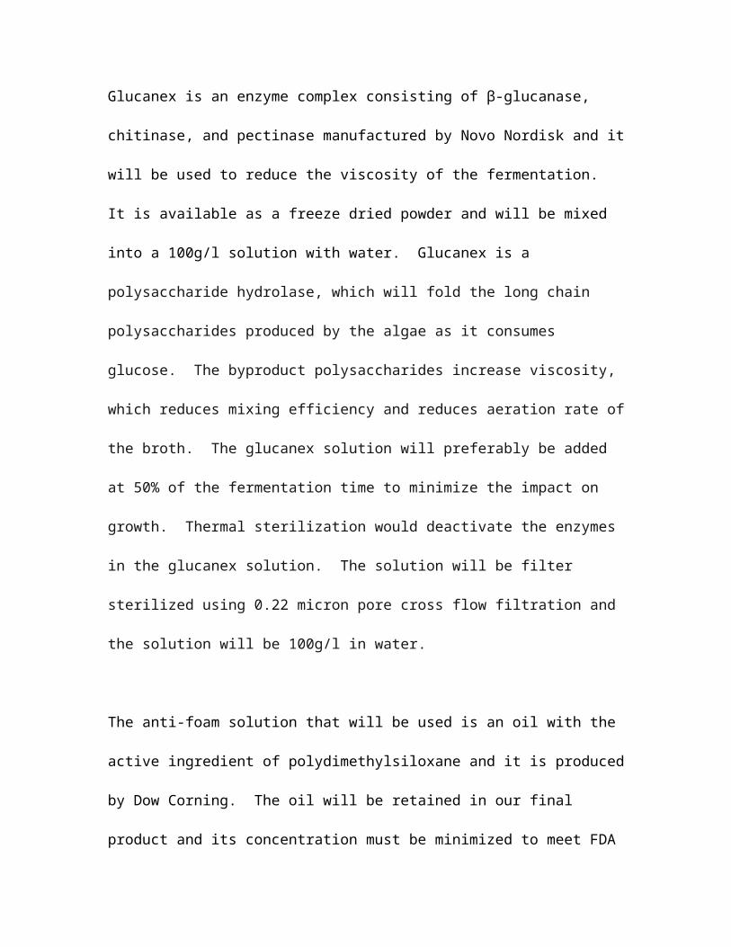
Glucanex is an enzyme complex consisting of β-glucanase, chitinase, and pectinase
manufactured by Novo Nordisk and it will be used to reduce the viscosity of the
fermentation. It is available as a freeze dried powder and will be mixed into a 100g/l
solution with water. Glucanex is a polysaccharide hydrolase, which will fold the long
chain polysaccharides produced by the algae as it consumes glucose. The byproduct
polysaccharides increase viscosity, which reduces mixing efficiency and reduces aeration
rate of the broth. The glucanex solution will preferably be added at 50% of the
fermentation time to minimize the impact on growth. Thermal sterilization would
deactivate the enzymes in the glucanex solution. The solution will be filter sterilized
using 0.22 micron pore cross flow filtration and the solution will be 100g/l in water.
The anti-foam solution that will be used is an oil with the active ingredient of
polydimethylsiloxane and it is produced by Dow Corning. The oil will be retained in our
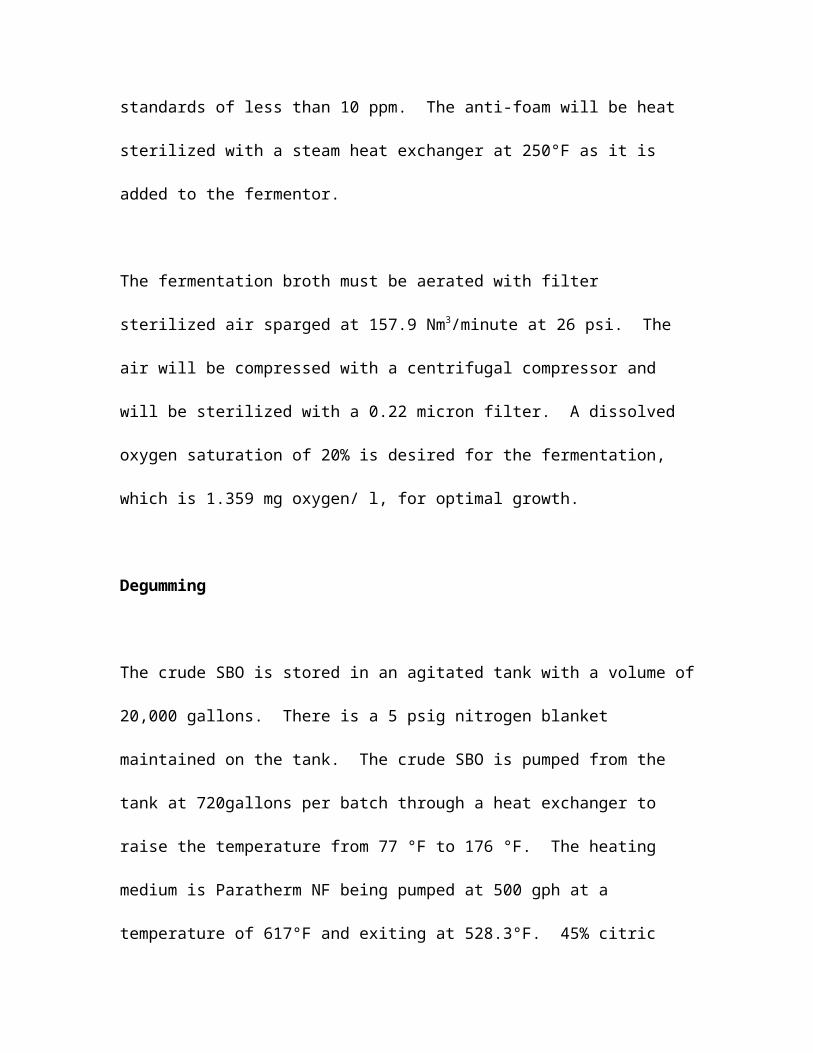
final product and its concentration must be minimized to meet FDA standards of less than
10 ppm. The anti-foam will be heat sterilized with a steam heat exchanger at 250°F as it
is added to the fermentor.
The fermentation broth must be aerated with filter sterilized air sparged at 157.9
Nm3/minute at 26 psi. The air will be compressed with a centrifugal compressor and will
be sterilized with a 0.22 micron filter. A dissolved oxygen saturation of 20% is desired
for the fermentation, which is 1.359 mg oxygen/ l, for optimal growth.
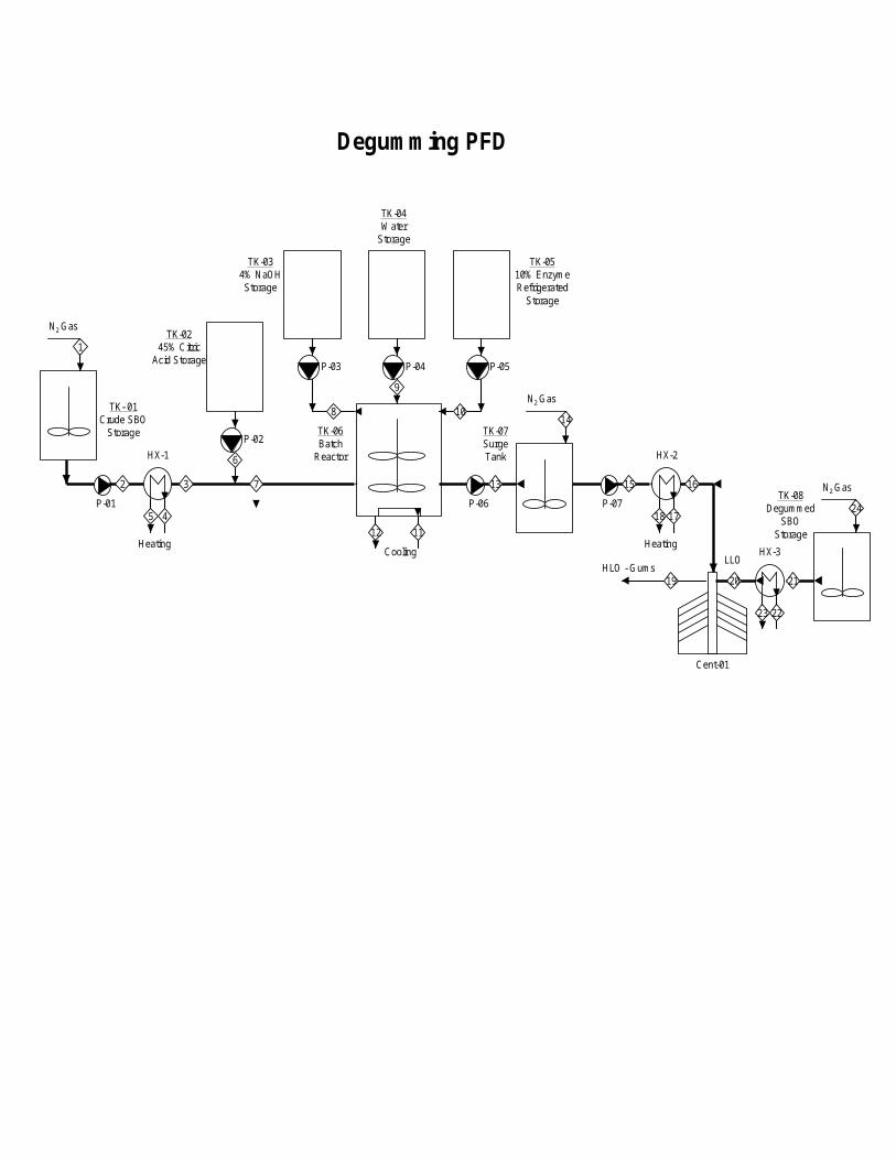
Degumming
The crude SBO is stored in an agitated tank with a volume of 20,000 gallons. There is a
5 psig nitrogen blanket maintained on the tank. The crude SBO is pumped from the tank
at 720gallons per batch through a heat exchanger to raise the temperature from 77 °F to
176 °F. The heating medium is Paratherm NF being pumped at 500 gph at a temperature
of 617°F and exiting at 528.3°F. 45% citric acid is pumped into the crude SBO stream at
0.07gallon per batch giving a pH of 4.06. Citric acid is stored in a 25 gallon tank. The
citric acid and crude SBO are mixed for 30 minutes prior to the temperature being
dropped to 122 °F by cooling water at a flow rate of 500 gph and an inlet temperature of
85 °F. The cooling water outlet temperature is 113.8 °F. The addition of 4% sodium
hydroxide is a controlled process in order to maintain a constant pH of 4.90 (±0.10) in the
batch reactor. 14.4 gallons of water is added to the batch reactor. The final additive to
the 1200 gallon batch reactor is 10% enzyme solution. The enzyme is Lecitase Ultra,
manufactured by Novozyme. The Lecitase Ultra is stored in a refrigerated storage tank at

41 °F. The mixing in the batch reactor continues for 6 hours, and then the solution is
pumped to a 1200 gallon surge tank with a 5 psig nitrogen blanket and a 50 rpm agitation
system. The surge tank is emptied over a 6 hour period with a 120 gallon per hour pump.
Out of the surge tank the solution is heated up from 122 °F to 158 °F by the Paratherm
NF. The Paratherm cools from 617 °F to 611.6 °F. After going through the heat
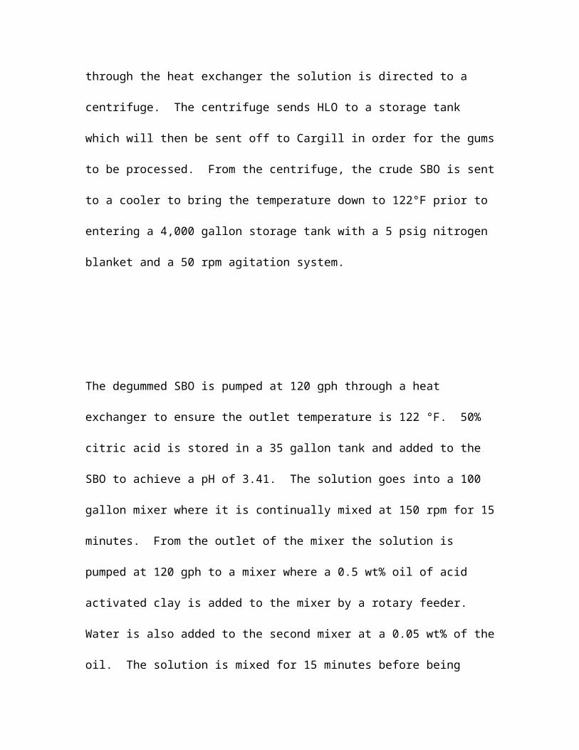
exchanger the solution is directed to a centrifuge. The centrifuge sends HLO to a storage
tank which will then be sent off to Cargill in order for the gums to be processed. From
the centrifuge, the crude SBO is sent to a cooler to bring the temperature down to 122°F
prior to entering a 4,000 gallon storage tank with a 5 psig nitrogen blanket and a 50 rpm
agitation system.
The degummed SBO is pumped at 120 gph through a heat exchanger to ensure the outlet
temperature is 122 °F. 50% citric acid is stored in a 35 gallon tank and added to the SBO
to achieve a pH of 3.41. The solution goes into a 100 gallon mixer where it is continually
mixed at 150 rpm for 15 minutes. From the outlet of the mixer the solution is pumped at
120 gph to a mixer where a 0.5 wt% oil of acid activated clay is added to the mixer by a
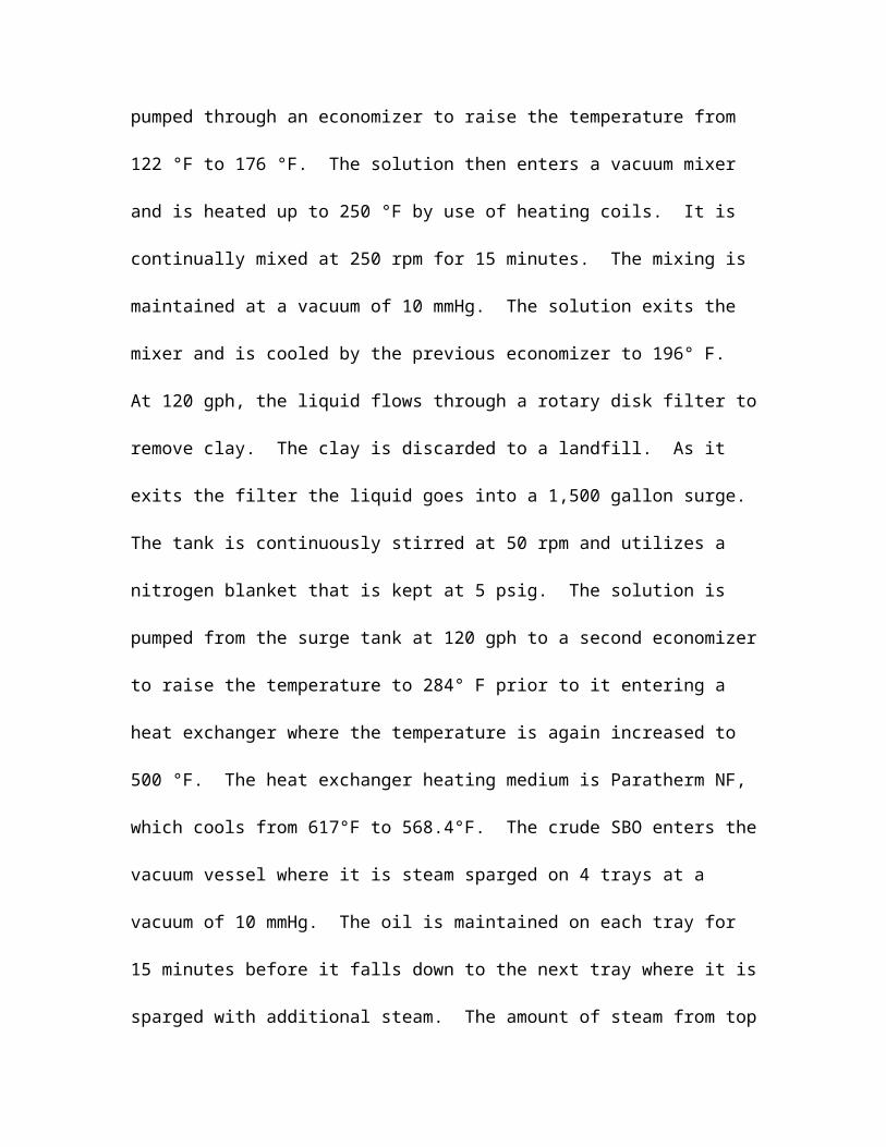
rotary feeder. Water is also added to the second mixer at a 0.05 wt% of the oil. The
solution is mixed for 15 minutes before being pumped through an economizer to raise the
temperature from 122 °F to 176 °F. The solution then enters a vacuum mixer and is
heated up to 250 °F by use of heating coils. It is continually mixed at 250 rpm for 15
minutes. The mixing is maintained at a vacuum of 10 mmHg. The solution exits the

mixer and is cooled by the previous economizer to 196° F. At 120 gph, the liquid flows
through a rotary disk filter to remove clay. The clay is discarded to a landfill. As it exits
the filter the liquid goes into a 1,500 gallon surge. The tank is continuously stirred at 50
rpm and utilizes a nitrogen blanket that is kept at 5 psig. The solution is pumped from
the surge tank at 120 gph to a second economizer to raise the temperature to 284° F prior
to it entering a heat exchanger where the temperature is again increased to 500 °F. The
heat exchanger heating medium is Paratherm NF, which cools from 617°F to 568.4°F.
The crude SBO enters the vacuum vessel where it is steam sparged on 4 trays at a
vacuum of 10 mmHg. The oil is maintained on each tray for 15 minutes before it falls
down to the next tray where it is sparged with additional steam. The amount of steam
from top to bottom is 0.1, 0.7, 1.5, 1.5 wt%, respective to the amount of oil. The steam,
FFA, citric acid, and water exit from the top of the vacuum vessel and are sent to Cargill
for processing. The refined oil leaves the vacuum vessel via a 120 gph pump through the
second economizer which lowers its temperature from 482 °F to 415.4 °F. At the outlet
of the economizer the oil goes through the heating coils of the vacuum mixer where its
temperature is decreased to 356 °F. The oil must be cooled down to 122 °F by cooling
water at 85° F entering the cooler and exiting at 108.4 °F. The refined oil enters the
4,000 gallon storage tank with a 5 psig nitrogen blanket and 50 rpm mixing.
Interesterification

The refined SBO is pumped from the storage to tank at 350 gph through a heat exchanger
to raise the temperature from 122 °F to 230 °F. The heating medium is Paratherm NF
which has a resulting temperature change of 617 °F to 542 °F. The refined SBO then
enters the interesterification mixing tank.
The hardfat SBO is stored in a 10,000 gallon tank with a nitrogen blanket at 5 psig and
continually stirred at 50 rpm. The hardfat SBO is pumped at 175 gph to a 1,000 gallon
processing tank where the hardfat SBO is heated from 77 °F to 122 °F while being mixed
at 50 rpm with a 5 psig nitrogen blanket on the tank. The tank is heated with Paratherm
NF entering at 500 gph at a temperature of 617 °F to maintain the temperature of the
hardfat SBO. The SBO is then pumped at 100 gph through a heat exchanger to raise the
temperature to 230 °F. The hardfat SBO then enters the interesterification mixing tank.
The hardfat and refined SBO are mixed and maintained at 230° F at 37.5 mmHg for 40
minutes. Cooling water is used to cool the tank to 194 °F, while still maintaining
vacuum. 99.8% sodium methoxide is added to the tank at 0.5 wt% of the oil in the
interesterification tank. Mixing is continued at 500 rpm for 30 minutes. Cooling water
cools the SBO down to 176 °F. The process is inactivated by 2 wt% addition of 20%
citric acid to the tank. Stirring is continued for an additional 15 minutes. When the
process is complete, the SBO is pumped at 500 gph through a rotary disk filter to remove
the sodium methoxide, which is sent to the landfill.
Water washing is done with soft water from a 7,500 gallon storage tank. The soft water
is used for two washing procedures. Each wash with soft water is done with 5 wt% oil in
a 500 gallon mixer, stirring at 150rpm. The mixing lasts for 10 minutes in each mixer.
At the outlet of each mixer is a centrifuge to handle the 500 gph oil and water mixture.
The waste from the centrifuge will need to be neutralized and disposed of. The washed
SBO leaves the second centrifuge to enter a 500 gallon atmospheric pan dryer. The
temperature is then increased to 230 °F for 30 minutes. The SBO is then pumped at 500
gph from the dryer to cooler to bring the temperature to 122 °F, using cooling water as
the medium utilized for the cooling. The SBO then enters a 5000 gallon storage tank
with a 5 psig nitrogen blanket and is mixed at 50 rpm.
Margarine Process
The margarine process is fairly straightforward, with no major chemical reactions or
exotic pieces of equipment. The ingredients are placed into two categories: the oil phase
and the water phase. The oil phase consists of the oils and the oil-soluble ingredients.
These are 669 kg / hr of the refined soybean oil gathered from the soybean refining
process, 22.9511 kg / hr of the DHA-rich algae oil taken from the harvested algae, 1.8
kg / hr of lecithin, 4.3 kg / hr of the mono and diglycerides, .00007 kg / hr of
ergocaliferol, .02 kg / hr of the beta-carotene, .002 kg / hr of the diacetyl, and .9 kg / hr
sorbic acid. These ingredients are prepared in an 1500 L oil phase preparation tank.
There are two of these tanks in order for the process to fun semi-continuously because
two tanks can be prepared at the same time. The water phase phase consists of the
potable, clean water and the sea salt. The water runs into the water preparation tanks at
154 kg / hr and the salt is added to the preparation at 12 kg / hr. These are prepared
together in a water phase preparation tank. There is only one of these tanks because the
ingredients are quickly and easily mixed together. After one batch is sent through,
another batch is quickly prepared. The water tank for this process is small, at 1000 L
because it is connected to the city water supply and is refilled as the water is used.
After these initial preparations, the oil phase is sent to one of the two 2000 L
emulsification tanks where it is heated with a warm water jacket over the tank. As it is
being mixed, the water phase is then slowly added, creating a water in oil emulsion. This
emulsion is heated to around 100 °F to allow for better mixing, and the emulsion tank
agitators stir the mixture with about 8 hp. After the emulsion is well-mixed, it is sent
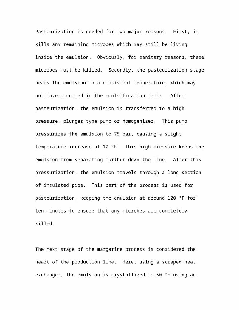
forward to a plate heat exchanger which heats the emulsion to 110 °F. Pasteurization is
needed for two major reasons. First, it kills any remaining microbes which may still be
living inside the emulsion. Obviously, for sanitary reasons, these microbes must be
killed. Secondly, the pasteurization stage heats the emulsion to a consistent temperature,
which may not have occurred in the emulsification tanks. After pasteurization, the
emulsion is transferred to a high pressure, plunger type pump or homogenizer. This
pump pressurizes the emulsion to 75 bar, causing a slight temperature increase of 10 °F.
This high pressure keeps the emulsion from separating further down the line. After this
pressurization, the emulsion travels through a long section of insulated pipe. This part of
the process is used for pasteurization, keeping the emulsion at around 120 °F for ten
minutes to ensure that any microbes are completely killed.
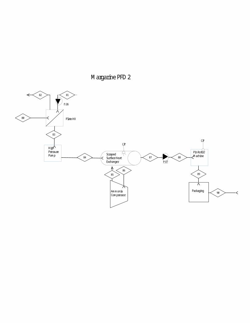
The next stage of the margarine process is considered the heart of the production line.
Here, using a scraped heat exchanger, the emulsion is crystallized to 50 °F using an
ammonia based refrigeration system. An external ammonia compressor is utilized in this
refrigeration system, with an ammonia circulation of 18 tons. After crystallizing, the
margarine is then kneaded in a pin rotor machine which ensures that the final margarine
project has the correct viscosity. Then the margarine is sent through a tub filling and
packaging machine, ready to be sent out the door.
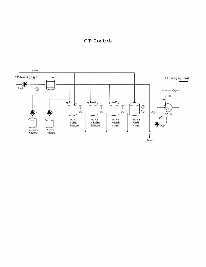
CIP Process
Cleaning and sanitizing equipment is critical in the food processing industry. The
cleaning in place (CIP) system is an integral part of all modern margarine production
facilities, preventing bacteria growth and assuring sanitary equipment conditions. The
CIP system involves the recirculation of the cleaning fluids through assembled food
processing equipment in a continuous circuit with rinse and detergent solutions at the
proper concentrations, temperatures, pressures and times. For a traditional margarine
products the normal equipment cleaning interval is once a week. However, the cleaning
interval is shorter for the products with a high water content, a low fat content, or a high
protein content.
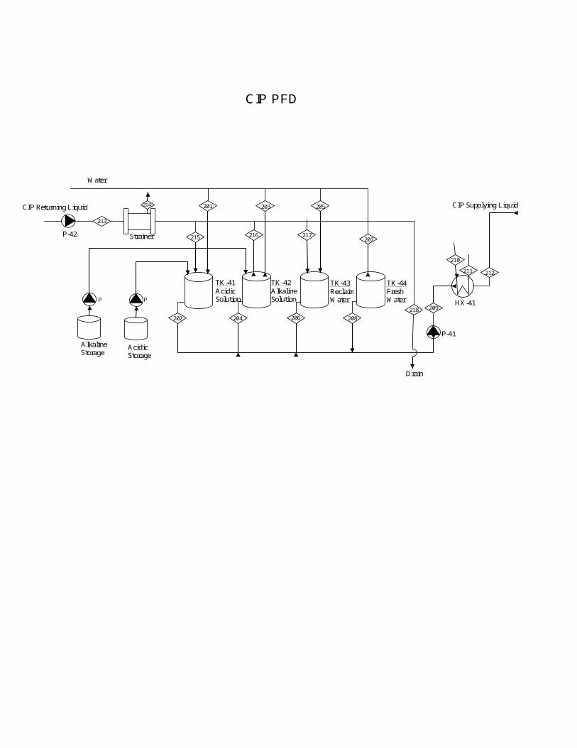
The CIP tanks can vary in size depending on the design and the necessary duty of the
system, but they should hold enough liquid to completely fill the largest cleaning circuit
plus a 25% reserve. The usual lay out for CIP set is to have three tanks, one that contains

fresh water, one that contains detergent, and one that contains reclaimed water. A fourth
tank with secondary detergents is found in some systems. The four CIP tank set is usually
used for margarine facilities. The tanks are usually round with a conical bottom, and
made with stainless steel.
CIP pumps fall into roughly three groups: delivery pumps, mixing pumps and return
pumps. Delivery pumps are usually centrifugal, offering high flow at relatively low
pressures and are designed to work best with a flooded suction. These are used to deliver
the cleaning solution to the portion of the plant that is being cleaned. Mixing pumps are
usually of the same design as delivery pumps, but have smaller capacities. These are used
to ensure adequate mixing of the detergents. Return pumps are used to return the cleaning
solution from the portions of the plant that are being cleaned back to the CIP tanks. They
should be designated to pump well even without a flooded suction; this allows them to
cope with the large quantities of air that become entrained in the cleaning solutions
during CIP.
Generally the most effective CIP process incorporates five steps:
1. An initial rinse;
Rinse with water at ambient temperature to remove any residues. 10 to 15 minutes
are usually sufficient for this part of the cycle.
2. Rinse with alkaline detergent;
Rinse with an alkaline detergent, typically a 2-2.5% solution of Caustic Soda
(NaOH) at about 70˚C for a time period of 20-30 minutes. This phase should
remove any organic matter.
3. Intermediate rinse with water;
Rinse with water at ambient temperature for a time period of 5 to 10 minutes. This
step should remove any residual detergents
4. Rinse with acidic detergent;
Rinse it with an acidic detergent, typically a 2.5% or lower concentration of Nitric
Acid (HNO₃) solution at ambient temperature for a time period of 10-15 minutes.
This phase should remove mineral salts, proteins, lime and other deposits.
5. Final rinse with clean water.
Rinse with clean water at ambient temperature to remove all traces of the cleaning
detergents. 10 to 15 minutes are usually sufficient for this part of the cycle.
During the CIP cycle it is important to keep the detergent concentrations constant; a
significant increase in concentrations can damage the system equipment, while a
significant decrease in concentration can negatively affect the detergents cleaning
efficiency.
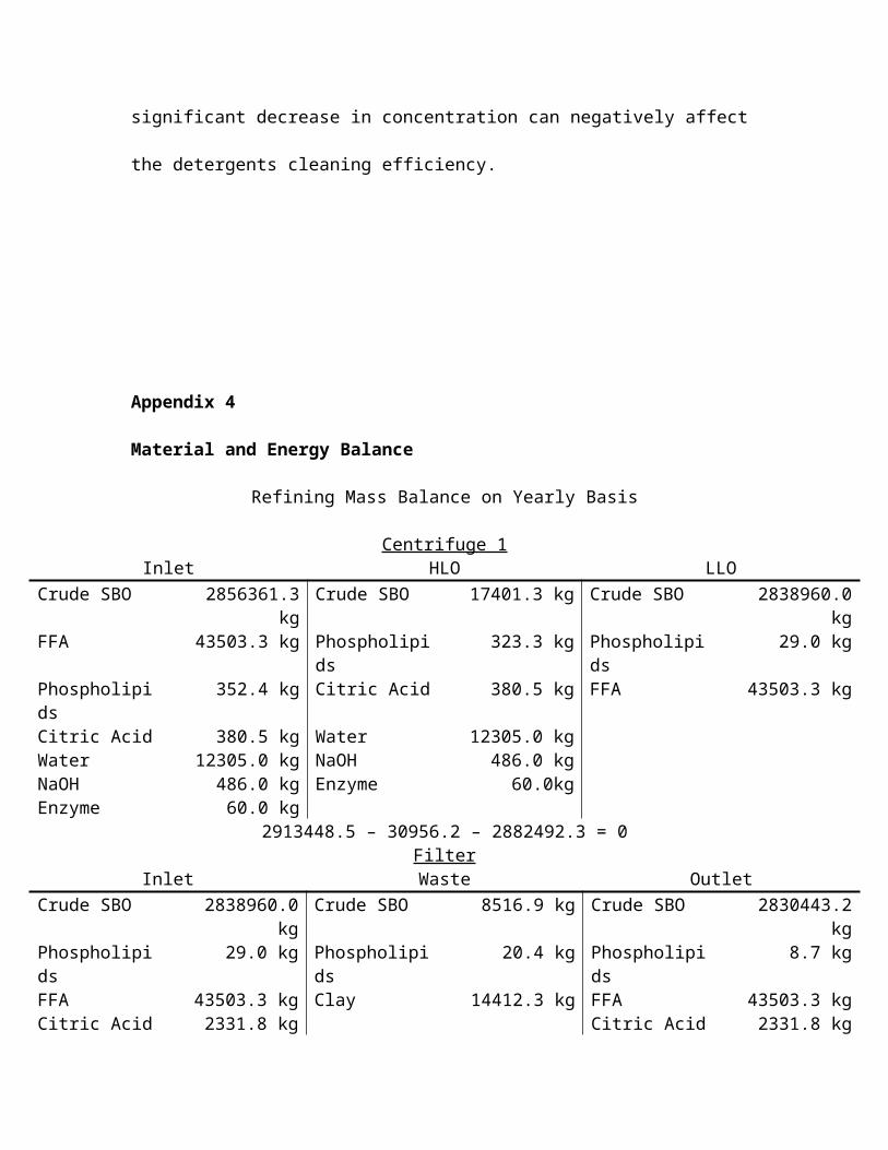
Appendix 4
Material and Energy Balance
Refining Mass Balance on Yearly Basis
Centrifuge 1Inlet HLO LLO
Crude SBO 2856361.3 kg Crude SBO 17401.3 kg Crude SBO 2838960.0 kgFFA 43503.3 kg Phospholipids 323.3 kg Phospholipids 29.0 kgPhospholipids 352.4 kg Citric Acid 380.5 kg FFA 43503.3 kgCitric Acid 380.5 kg Water 12305.0 kgWater 12305.0 kg NaOH 486.0 kgNaOH 486.0 kg Enzyme 60.0kgEnzyme 60.0 kg
2913448.5 – 30956.2 – 2882492.3 = 0Filter
Inlet Waste OutletCrude SBO 2838960.0 kg Crude SBO 8516.9 kg Crude SBO 2830443.2 kgPhospholipids 29.0 kg Phospholipids 20.4 kg Phospholipids 8.7 kgFFA 43503.3 kg Clay 14412.3 kg FFA 43503.3 kgCitric Acid 2331.8 kg Citric Acid 2331.8 kgClay 14412.3 kg Water 4762.7 kgWater 4762.7 kg
2903999.3 – 22949.6 – 2881049.7 = 0Sparging
Inlet Waste OutletCrude SBO 2830443.2 kg Crude SBO 28304.4 kg Crude SBO 2787986.5 kgPhospholipids 8.7 kg Phospholipids 5.8 kg Phospholipids 2.9 kgFFA 43503.3 kg FFA 42633.3 kg FFA 870.0 kgCitric Acid 2331.8 kg Citric Acid 2331.8 kg Mono/
Diglycerides14152.3 kg
Water 4762.7 kg Water 4762.7 kgSteam 109533.3 kg Steam 109533.3 kg
2990582.0 – 187571.3 – 2803011.7 = 0Interesterification
Inlet OutletCrude SBO 2787986.5 kg SBO 3488739.4 kgPhospholipids 2.9 kg Phospholipids 2.9 kgFFA 870.0 kg FFA 870.0 kgMono/Diglycerides
14152.2 kg Mono/Diglycerides
14152.2 kg
SBO Hardfat 700752.9 kg Citric Acid 18688.7 kgCitric Acid 18688.7 kg CH3ONa 6863.4 kgCH3ONa 6863.4 kg Soft Water 60359.0 kgSoft Water 60359.0 kg
3589675.6 - 3589675.6 = 0Filter

Inlet Waste OutletSBO 3488739.4 kg SBO 13955.0 kg SBO 3474784.5 kgPhospholipids 2.9 kg CH3ONa 5998.7 kg Phospholipids 2.9 kgFFA 870.0 kg FFA 870.0 kgMono/Diglycerides
14152.2 kg Mono/Diglycerides
14152.2 kg
Citric Acid 18688.7 kg Citric Acid 18688.7 kgCH3ONa 6863.4 kg CH3ONa 864.7 kgSoft Water 60359.0 kg Soft Water 60359.0 kg
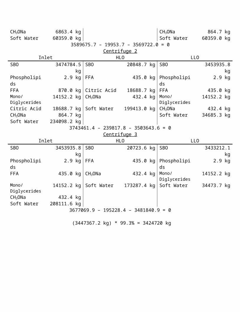
3589675.7 – 19953.7 – 3569722.0 = 0Centrifuge 2
Inlet HLO LLOSBO 3474784.5 kg SBO 20848.7 kg SBO 3453935.8 kgPhospholipids 2.9 kg FFA 435.0 kg Phospholipids 2.9 kgFFA 870.0 kg Citric Acid 18688.7 kg FFA 435.0 kgMono/Diglycerides
14152.2 kg CH3ONa 432.4 kg Mono/Diglycerides
14152.2 kg
Citric Acid 18688.7 kg Soft Water 199413.0 kg CH3ONa 432.4 kgCH3ONa 864.7 kg Soft Water 34685.3 kgSoft Water 234098.2 kg
3743461.4 – 239817.8 – 3503643.6 = 0Centrifuge 3
Inlet HLO LLOSBO 3453935.8 kg SBO 20723.6 kg SBO 3433212.1 kgPhospholipids 2.9 kg FFA 435.0 kg Phospholipids 2.9 kgFFA 435.0 kg CH3ONa 432.4 kg Mono/
Diglycerides14152.2 kg
Mono/Diglycerides
14152.2 kg Soft Water 173287.4 kg Soft Water 34473.7 kg
CH3ONa 432.4 kgSoft Water 208111.6 kg
3677069.9 – 195228.4 – 3481840.9 = 0
(3447367.2 kg) * 99.3% = 3424720 kg

Appendix 5
Calculations

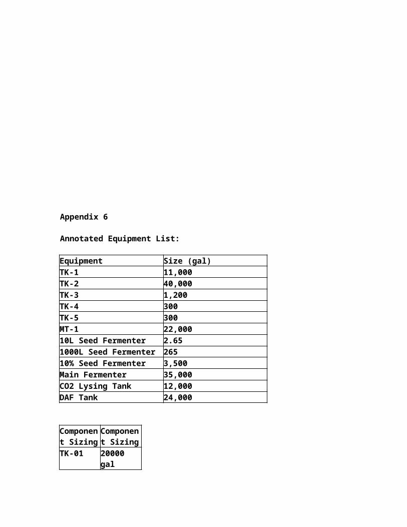
Appendix 6
Annotated Equipment List:
Equipment Size (gal)TK-1 11,000TK-2 40,000TK-3 1,200TK-4 300TK-5 300MT-1 22,00010L Seed Fermenter 2.651000L Seed Fermenter 26510% Seed Fermenter 3,500Main Fermenter 35,000CO2 Lysing Tank 12,000DAF Tank 24,000
Component Sizing
Component Sizing
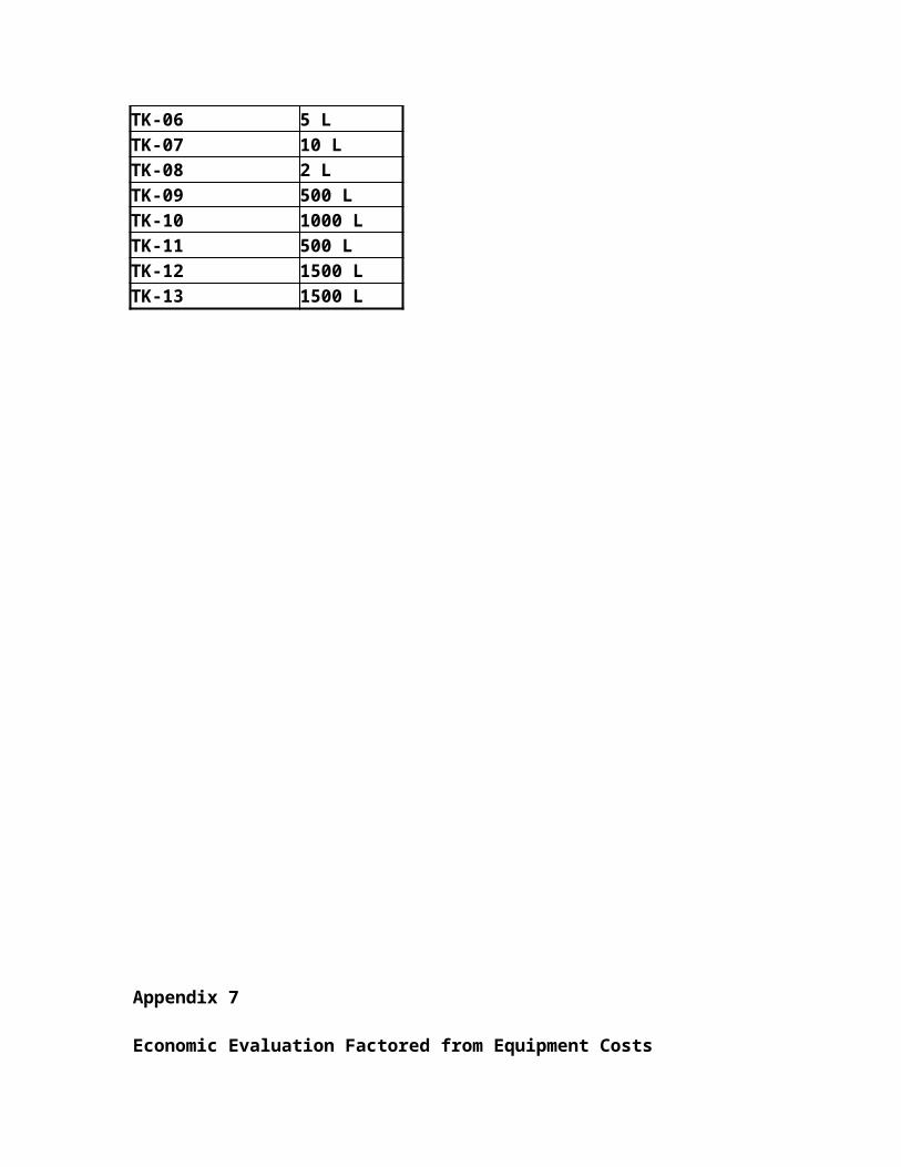
TK-01 20000 galTK-02 25 galTK-03 400 galTK-04 600 galTK-05 15 galTK-06 1500 galTK-07 1500 galTK-08 4000 galTK-09 35 galTK-10 250 galTK-11 600 galTK-12 100 galTK-13 1500 galTK-14 4000 galTK-15 10000 galTK-16 1000 galTK-17 250 galTK-18 1200 galTK-19 400 galTK-20 7500 gal

TK-21 400 galTK-22 5000 gal
MX-1 100 galMX-2 100 galMX-3 500 galMX-4 500 gal
Component Sizing Component Sizing
HX-1 202490.49 BTU/hrHX-2 12603.83 BTU/hrHX-3 12603.83 BTU/hrHX-4 15340.19 BTU/hrHX-5 19900.73 BTU/hrHX-6 36567.59 BTU/hrHX-7 109454.00 BTU/hrHX-8 39541.70 BTU/hrHX-9 97016.05 BTU/hrHX-10 49571.68 BTU/hrHX-11 159620.87 BTU/hrHX-12 92228.34 BTU/hrHX-13 46342.34 BTU/hr
Component SizeP-01 0.25 GPMP-02 3.5 GPMP-03 1 GPMP-04 1 GPMP-05 3.5 GPMP-06 110 GPMP-07 4.25 GPMEmulsion Tank 1 2000 LEmulsion Tank 2 2000 LHigh Pressure Pump 2475 L / hrPlate Heat Exchanger 6 ft^2Scraped Surface Heat Exchanger 2150 L / hrPin Rotor Machine 2000 L/hrTub Filling Machine 2740 L/hrAmmonia Compressor 18 ton

Component SizeTK-01 1000 LTK-02 5000 LTK-03 20 LTK-04 2 LTK-05 2 LTK-06 5 LTK-07 10 LTK-08 2 LTK-09 500 LTK-10 1000 LTK-11 500 LTK-12 1500 LTK-13 1500 L
Appendix 7
Economic Evaluation Factored from Equipment Costs
Appendix 8
Utilities
Appendix 9
Conceptual Control Scheme
Main Fermenter
Cooling Water
SpargedSteam
Vented Air 13
14
Sterile Air
10% Seed Fermenter
Cooling Water
SpargedSteam
Vent
9
Sterile Air
1000 L Seed Fermenter
10 L Seed Fermenter
250 mLShake Flasks
Water Water
Direct Steam Injection
MT-1
Salt
Ethanol Bottoms
Glucose
Sterile Glucanex
Sterile Anti-foam
1
2
3
4 5
7
8
11
10
12Compressor 1
Filter 11Air
Filter 2
TK-1 TK-2 TK-3
TK-4 TK-5
STEX-1
Steam 4a
P- 1
P- 2
P- 3
P- 5 P- 6
P- 7 P- 8
Filter 3
To DAF
15
P- 9
Harvest Tank
PIC
QIC
QIC FIC
FIC
TIC
TIC
TIC
TICCompressor 1Air
PIC
Filter 21
PIC
PIC
QIC
P- 10
P- 11
QIC
QIC
QIC
QIC
FIC
Fermentor Controls
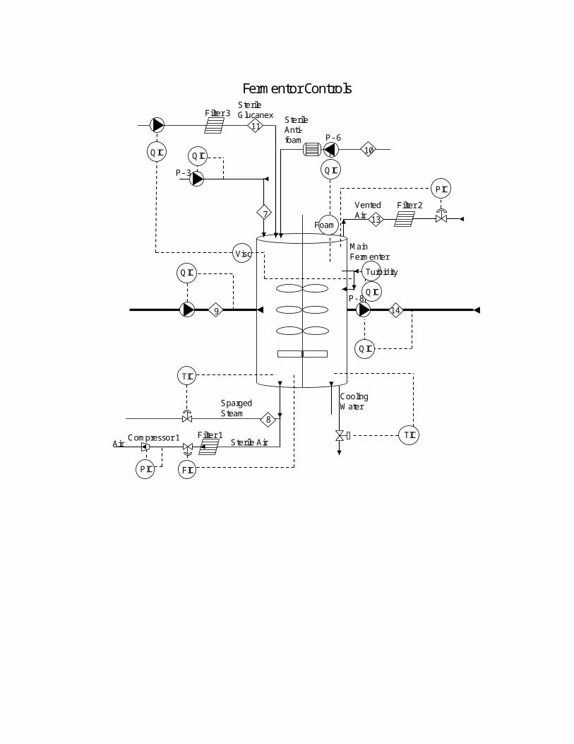
Main Fermenter
Cooling WaterSparged
Steam
Vented Air 13
Sterile Air
Sterile Glucanex Sterile
Anti-foam
7
8
11
Filter 1
Filter 2
P- 8
Filter 3
TIC
14
Compressor 1Air
PIC
PIC
FIC
QIC
QIC
9
P- 3
TIC
10QIC
Visc
Foam
QIC
P- 6
Turbidity
QIC
QIC
Fermentor Controls

Rxn tank A
Rxn tank B
P-01
FermentedAlgae
FermentedAlgae
Sterilized AirSterilize Air
Vented Air
Conc. Algae
Water
45
18
16
15
17
Dissolved Air Flotation Controls
12
Sterilized Air
Sterilized Air
20
19
22 23
21
46Water
1
2
P10
P11
P12
Water to Cargill treatment
Tk-6
Tk-7
DAF Tk-7
PIC
Cv-21
Cv-23
PIC
FIC
Cv-20
FIC
18 18
Cv-22
FIC
FICFIC
Cv-24
Cv-25
FIC
Cv-26
3
Baffle trayTowerTk- 8
CO2 Lysing Controls
Conc. Algae
Sterilized CO2
CO2 AbsorbedAlgae
LysedAlgae&CO2
Vented CO2
LysedAlgae
ThrottleValve
23
24
Filter 4
CO 2
Compressor 2
25 26
27
Stir tank
P13
P1429
Lysed Algae TowerTk- 9
Cv-30
FIC
28
FIC
Cv-27
Cv-29
Cv-28FIC
Cv-30
4748
Steam in & out
TIC
Cv-31
PIC

Main Centrifuge Controls
Centrifuge
Lysed Algae
Lysed Algae
Algae Oil
2931
30
Algae Oil Holding tankTK-10
34
P1535
Algae Oil
FICCv-32
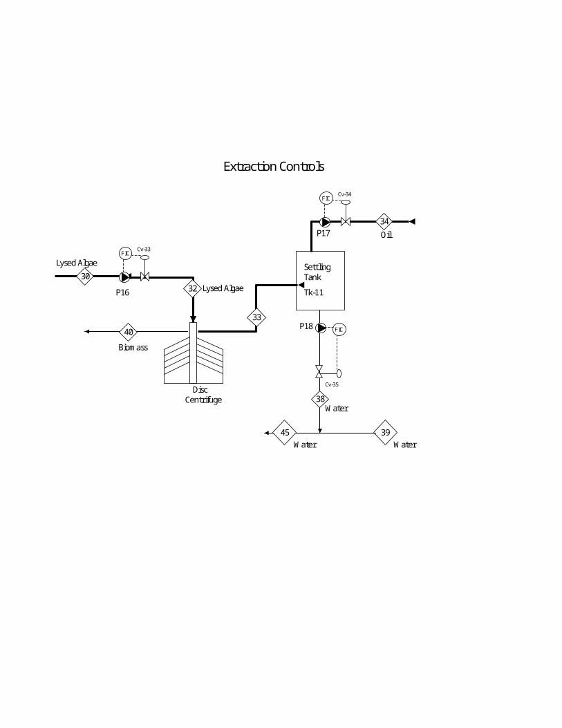
Extraction Controls
Oil
Settling Tank
Tk-11
Water
33
Disc Centrifuge
Lysed Algae
P16
40
30
34
38
32 Lysed Algae
Biomass
39
P18
P17
Water
45Water
FICCv-33
FICCv-34
Cv-35
FIC
Separation and Drying Processes Controls
Rotary
Dryer
42
Dynamic Cross Flow Filtration
Biomass P19
40
43
Biomass /water tank
Tk-12
Dry Biomass
P20
37 water vapor
41
Biomass
Biomass
FICCv-36
49Steam in
TICCv-38
50 Steam out
Conveyor Belt
Collection Hopper
Conveyor Belt
Shipping container
Table Spread Distributor
Dried Algae Distributor
39Water
Cv-37
P21
FIC
TK- 51Crude SBO
Storage
P-51
N2 GasTK-52
45% CitricAcid Storage
P-52
P-53P-54
TK-534% NaOHStorage
TK-5410% EnzymeRefrigerated
Storage
N2 Gas
HLO - Gums
BatchReactor
P-55
P-56
TK-55SurgeTank
N2 Gas
TK-56Degummed
SBOStorage
HX-5
CLR-1LLO
HX-6
Cent-5
TIC
TIC
FIC
PIC
PIC
PIC
TIC
pHCQIC
QIC LIC
TCFIC
LIC
LIC

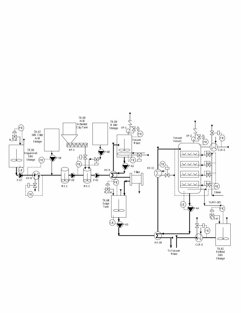
N2 Gas
TK-56Degummed
SBOStorage
HX-8
TK-5750% Citric
AcidStorage
P-57
P-58
TK-58Acid
ActivatedClay Tank
P-59
P-60
TK-59Water
Storage
P-61
HX-9P-62
VP-1
VacuumMixer
N2 Gas
TK-60SurgeTank
P-63
MX-1MX-1
VP-2
Steam
To MX-101
P-64
N2 Gas
TK-61Refined
SBOStorage
HX-10
HX-11
CLR-2
CLR-3
Filter
VacuumVessel
RP-1
TIC
TICTIC
FIC
FIC
PIC
PIC
PIC
PIC
PIC
FIC
To VacuumMixer
LIC
FIC
FIC
LIC
LIC

N2 Gas
TK-61Refined
SBOStorage
N2 Gas
TK-62SBO
HardfatStorage
N2 Gas
TK-63SBO
HardfatHeating
Tank
P-66
P-67
HX-14
HX-15
P-68
TK-64CH3ONaStorage
TK-66MixingTank
P-69
P-70
Filter
TK-67Soft
WaterStorage
HX-16
HLO
P-71
P-72 P-73HLO
Cent-7Cent-6
TK-6520% Citric
AcidStorage
N2 GasTK-68SBO
Storage
CLR-4
MX-3 MX-4
WaterSoftener
P-65
TIC
TIC
TIC
TIC
PIC
PIC
PIC
PIC
FIC
TIC
FIC
QIC
FIC
FIC
LICQIC
TC
FIC
LICTC
TC
N2 Gas
PIC
FIC
QICLIC
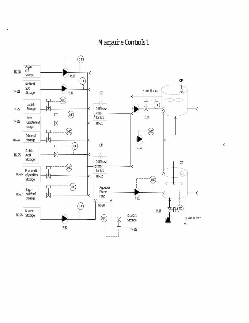
E
Algae OilStorage
Refined SBO Storage
LecithinStorage
Beta CaroteneStorage
DiacetylStorage
SorbicAcidStorage
Mono- diglyceridesStorage
Ergo-califerolStorage
WaterStorage
Oil
Pasteurization
CIP
Warm Water
Aqueous PhasePrep.
TK-20
TK-21
TK-22
TK-23
CIPCIP
TK-24
TK-25
TK-26
TK-27
TK-30
TK-31
TK-32
Oil Phase Prep.Tank 1
CIP
P-30
P-31
P-32
P-33
Warm Water
Oil Oil Phase Prep.Tank 1
CIP
Sea SaltStorage
TK-29
P-34
TK-28
CIP
Margarine Controls 1
Warm Water
QIC
QIC
QIC
QIC
QIC
QIC
QIC
QIC
QIC
QIC
QIC
QIC
P-35
P-35TIC
TIC

High Pressure Pump
AmmoniaCompressor
Pin Rotor MachineScraped
Surface Heat Exchanger
Tub Filling and Packaging
P-37
CIPCIP
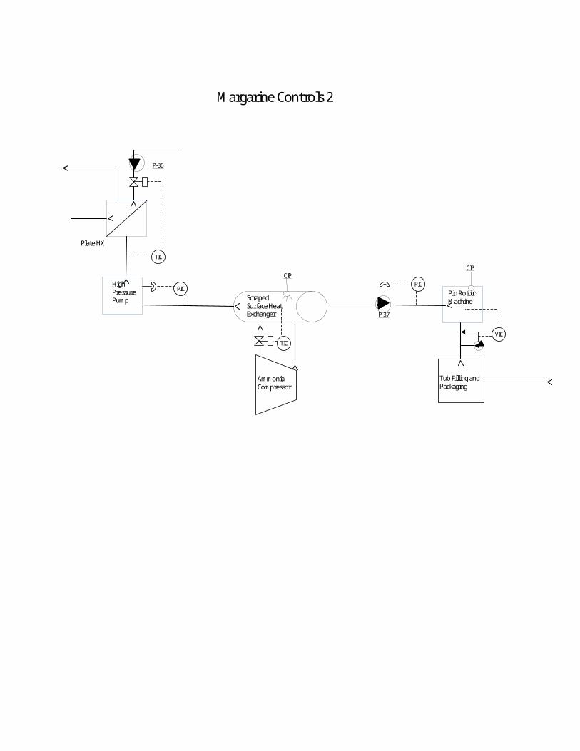
Margarine Controls 2
Plate HX
P-36
TIC
TICVIC
PICPIC

TK-41Acidic Solution
TK-42Alkaline Solution
TK-43Reclaim Water
TK-44FreshWater
Alkaline Storage
Acidic Storage
CIP Returning Liquid
Water
HX-41
CIP Supplying Liquid
Drain
P-41
P-42
PP
LIC
LIC
LIC
LIC
LIC
LIC
LIC
LIC
FIC
TICFIC Strainer
CS
CIP Controls

Control Descriptions:
Extraction and Lysing
Stream 15 (FIC)Stream 15 is divided into 2 equal streams, 16 and 17, that go into reaction tanks A and B and the feed inlet control valve (Cv-20) is a mass flow rate measurement equalizing valve that ensure that stream 16 and 17 are of equal valve and direct flow to one of the streams if they are not equal.
Reaction tanks A and BThe fermentation broth will be pumped out of each of these and controlled by mass flow meters (Cv-23 & 22) that allow the pumps to operate at specified gpm flow rate and the valves will open or close adjusting for a constant specified gpm. The air inlet flow rate will be controlled by an inlet pressure valve (Cv-21) and the pressure is regulated at 500 Kg per hour, the valve will open or closed if the 500 Kg per hour is not maintained.
DAF tank 7The Dissolved Air Flotation tank has a regulating valve (Cv-24) for the in air that is maintained at 1000 Kg/hour and the valve will adjust to maintain this flow rate. The waste water being pumped out the tank will be maintained at specified gallons per minute by the regulating valve (Cv-26) and this valve will open or close to adjust for the correct gpm.
CO 2 Absorption TowerThe absorption tower is maintained at 150 PSI and a pressure relief valve (Cv-30) if the pressure is higher than 150 PSI the valve will open and relieve the excess pressure. The CO 2 is pumped into the tower at 150 PSI and the control valve (Cv-29) will open and or close to maintain the appropriate pressure. The tower also has a recirculation pump that operates at set gpm and valve (Cv-27) adjusts to ensure the correct gpm is applied for recirculation.
CO 2 Throttling and lysing Tower tank 9The control valve (Cv-28) maintains the 150 psi and will adjust according to maintain the pressure going into the throttling valve. The lysing tower is maintained at a temperature of 80ºC by steam and the valve (Cv-31) and this valve is a temperature control valve that opens and closes to keep the specific temperature of 80ºC. The lysed algae is pumped from the tower and controlled by mass flow meters (Cv-30) that allow the pump to operate at specified gpm and the valve will open or close adjusting for a constant specified gpm.
Storage tank 10
The algae oil is pumped from this storage tank and controlled by mass flow meters (Cv-32) that allow the pump to operate at specified gpm and the valve will open or close adjusting for a constant specified gpm.
Stream 30The lysed aglae is pumped from pumped from the first centrifuge in a second centrifuge and is controlled by a mass flow meter (Cv-33) that allow the pump to operate at specified gpm and the valve will open or close adjusting for a constant specified gpm.
Settling tank 11The waste water being pumped out the tank will be maintained at specified gallons per minute by the regulating valve (Cv-35) and this valve will open or close to adjust for the correct gpm. The oil is be pumped from this tank also and will be maintained at specified gallons per minute by the regulating valve (Cv-34) and this valve will open or close to adjust for the correct gpm.
Biomass Storage tank 12The Biomass and water being pumped out of this tank will be feed into a third centrifuge and will be maintained at specified gallons per minute by the regulating valve (Cv-36) and this valve will open or close to adjust for the correct gpm into the centrifuge. The water leaving the centrifuge will be pumped into a series of pipes that collects all the waste water and vavle (Cv-37) will open or close the valve to ensure the proper gpm is maintained.
Rotary DryerThe rotary dyer uses steam to dry the biomass and the steam will be regulated by valve (Cv-38) which will regulate the steam inlet by opening and or closing to maintain the correct drying temperature.
Refining
TK-51,55,56,60,61,62,63,66,68 (PIC)All SBO storage tanks will have a nitrogen blanket of 0.5psig place on them. The controllers will be dead band controller to allow the pressure to get to the required amount, and then the valve will go shut.
P-51,52 (FIC)The flow into the batch reactor will be controlled to allow only 720 gallons of crude SBO to enter the batch reactor per batch. This quantity will be sensed by the controller and match the amount of 45% citric acid flowing into the batch reactor.
HX-5,6,8,11,14,15,16, Heating Coils of TK-63 and Vacuum Mixer, Cooling Coils of TK-66 and Batch Reactor (TIC)
The SBO oil will be temperature monitored on the outlet of the heat exchangers in order to control the position of a valve positioned on the outlet of the heating/cooling medium to control flow. The heating/cooling coils will have temperature monitoring of the associated tanks. The temperature sensor will adjust a valve on the return line of heating/cooling medium.
Batch Reactor (pHC)The pH of the batch reactor will be monitored in order to maintain it at 4.8-5.0. A small pump will circulate the liquid from the batch reactor through a line where the pH will be monitored. The 4% NaOH will be added accordingly to maintain the proper pH.
Batch Reactor, P-54, P-55 (LIC, TC, FIC, TC)The level in the batch reactor will be monitored to control when the impellers can begin mixing. Once mixing begins, there will be a 30 minute time delay until the addition of the enzyme. The enzyme will be monitored for flow in order to secure the pump when the proper amount has been added. The mixing will continue for 6 hours, and then the mixer will be secured. Once the mixer is secured P-55 will pump the contents of the batch reactor to the surge tank.
P-56 (LIC)In order to create a continuous process, there will be level control from the surge tank starting the flow of P-56. The pump will shut off when level goes below a desired level.
CLR-1,2,3 (FIC)There will be continuous flow of cooling medium through the cooler. The hot liquid flow will be monitored and will adjust the outlet flow of cooling water in order to give an adequate cooling amount.
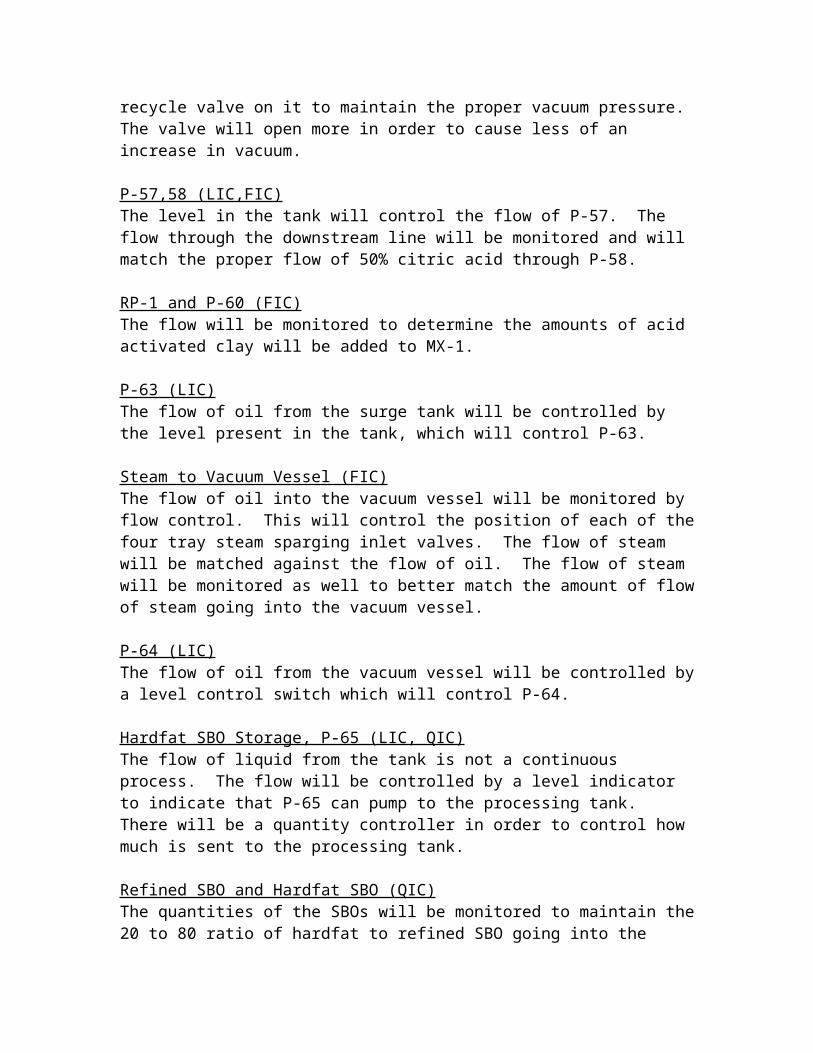
VP-1,2 (PIC)Pressure sensors will monitor the vacuum pressure in the tank. The vacuum pump will run continuously and have a recycle valve on it to maintain the proper vacuum pressure. The valve will open more in order to cause less of an increase in vacuum.
P-57,58 (LIC,FIC)The level in the tank will control the flow of P-57. The flow through the downstream line will be monitored and will match the proper flow of 50% citric acid through P-58.
RP-1 and P-60 (FIC)The flow will be monitored to determine the amounts of acid activated clay will be added to MX-1.
P-63 (LIC)The flow of oil from the surge tank will be controlled by the level present in the tank, which will control P-63.
Steam to Vacuum Vessel (FIC)

The flow of oil into the vacuum vessel will be monitored by flow control. This will control the position of each of the four tray steam sparging inlet valves. The flow of steam will be matched against the flow of oil. The flow of steam will be monitored as well to better match the amount of flow of steam going into the vacuum vessel.
P-64 (LIC)The flow of oil from the vacuum vessel will be controlled by a level control switch which will control P-64.
Hardfat SBO Storage, P-65 (LIC, QIC)The flow of liquid from the tank is not a continuous process. The flow will be controlled by a level indicator to indicate that P-65 can pump to the processing tank. There will be a quantity controller in order to control how much is sent to the processing tank.
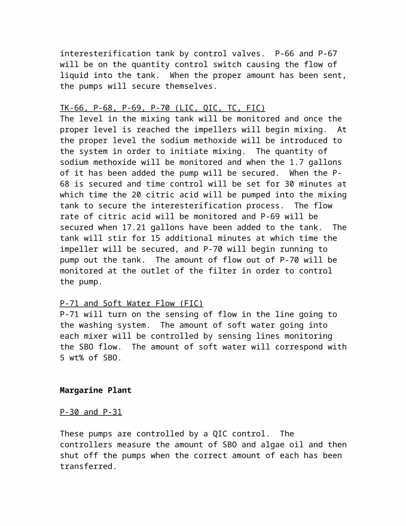
Refined SBO and Hardfat SBO (QIC)The quantities of the SBOs will be monitored to maintain the 20 to 80 ratio of hardfat to refined SBO going into the interesterification tank by control valves. P-66 and P-67 will be on the quantity control switch causing the flow of liquid into the tank. When the proper amount has been sent, the pumps will secure themselves.
TK-66, P-68, P-69, P-70 (LIC, QIC, TC, FIC)The level in the mixing tank will be monitored and once the proper level is reached the impellers will begin mixing. At the proper level the sodium methoxide will be introduced to the system in order to initiate mixing. The quantity of sodium methoxide will be monitored and when the 1.7 gallons of it has been added the pump will be secured. When the P-68 is secured and time control will be set for 30 minutes at which time the 20 citric acid will be pumped into the mixing tank to secure the interesterification process. The flow rate of citric acid will be monitored and P-69 will be secured when 17.21 gallons have been added to the tank. The tank will stir for 15 additional minutes at which time the impeller will be secured, and P-70 will begin running to pump out the tank. The amount of flow out of P-70 will be monitored at the outlet of the filter in order to control the pump.
P-71 and Soft Water Flow (FIC)P-71 will turn on the sensing of flow in the line going to the washing system. The amount of soft water going into each mixer will be controlled by sensing lines monitoring the SBO flow. The amount of soft water will correspond with 5 wt% of SBO.
Margarine Plant
P-30 and P-31
These pumps are controlled by a QIC control. The controllers measure the amount of SBO and algae oil and then shut off the pumps when the correct amount of each has been transferred.

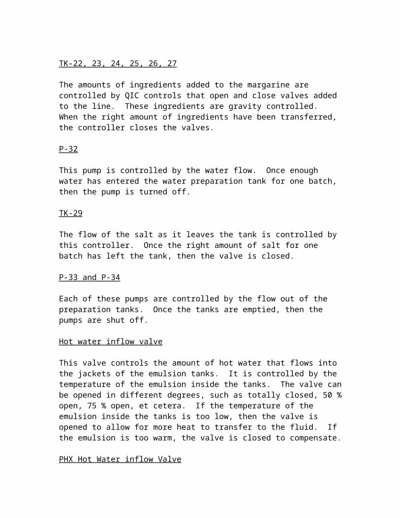
TK-22, 23, 24, 25, 26, 27
The amounts of ingredients added to the margarine are controlled by QIC controls that open and close valves added to the line. These ingredients are gravity controlled. When the right amount of ingredients have been transferred, the controller closes the valves.
P-32
This pump is controlled by the water flow. Once enough water has entered the water preparation tank for one batch, then the pump is turned off.
TK-29
The flow of the salt as it leaves the tank is controlled by this controller. Once the right amount of salt for one batch has left the tank, then the valve is closed.
P-33 and P-34
Each of these pumps are controlled by the flow out of the preparation tanks. Once the tanks are emptied, then the pumps are shut off.
Hot water inflow valve
This valve controls the amount of hot water that flows into the jackets of the emulsion tanks. It is controlled by the temperature of the emulsion inside the tanks. The valve can be opened in different degrees, such as totally closed, 50 % open, 75 % open, et cetera. If the temperature of the emulsion inside the tanks is too low, then the valve is opened to allow for more heat to transfer to the fluid. If the emulsion is too warm, the valve is closed to compensate.
PHX Hot Water inflow Valve
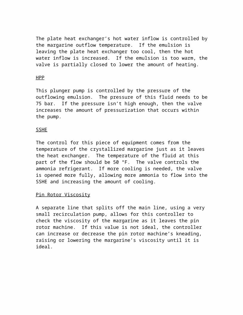
The plate heat exchanger’s hot water inflow is controlled by the margarine outflow temperature. If the emulsion is leaving the plate heat exchanger too cool, then the hot water inflow is increased. If the emulsion is too warm, the valve is partially closed to lower the amount of heating.
HPP
This plunger pump is controlled by the pressure of the outflowing emulsion. The pressure of this fluid needs to be 75 bar. If the pressure isn’t high enough, then the valve increases the amount of pressurization that occurs within the pump.
SSHE
The control for this piece of equipment comes from the temperature of the crystallized margarine just as it leaves the heat exchanger. The temperature of the fluid at this part of the flow should be 50 °F. The valve controls the ammonia refrigerant. If more cooling is needed, the valve is opened more fully, allowing more ammonia to flow into the SSHE and increasing the amount of cooling.
Pin Rotor Viscosity
A separate line that splits off the main line, using a very small recirculation pump, allows for this controller to check the viscosity of the margarine as it leaves the pin rotor machine. If this value is not ideal, the controller can increase or decrease the pin rotor machine’s kneading, raising or lowering the margarine’s viscosity until it is ideal.
Appendix 10
General Arrangement – Major Equipment Layout
Overall Plant Layout:
Otis Rd
Cargill
A
B
C
D
E
F
A. Storage/BoilersB. FermentationC. Offices/Labs/Miscellaneous SpaceD. Water Cooling TowerE. SBO RefiningF. Margarine Processing
Wind DirectionGate
General Plant LayoutAlpha Algae Plant1928 SE Otis RdCedar Rapids, IA 52401

S2
Seed 1
S1
S4
S3
Seed 2
Seed 3
Seed 4
Mix Tank
Fermenter 1
Fermenter 2
Fermenter 3
Fermenter 4
Harvest Tank
DAF
RXN 1
RXN 2
Absorption
Lysed Tank
Lipid Storage
Centrifuge 1 Centrifuge 2
C3 C4 Dryer
Glucose Storage
Ethanol Bottoms
Glucanex Antifoam
Salt Boiler
Cooling Tower
Electrical Room
85 ft
35 ft
115 ft
Fermentation Layout

SSHE
AmmoniaCompressor
Filling,Packing
Margarine Plant First Floor Layout
= 4 feet
CIP system
Emulsion Tanks
Ingredient PreparationTanks
HPP
Margarine Plant Mezzanine Layout
Electrical Room
Ingredient Storage Tank Area
= 4 feet
Appendix 11
Distribution and End-use Issues Review

Appendix 12
Constraints Review

Appendix 13
Applicable Standards
Sanitary Design
Equipment Design
• Cleanable to microbial level• Made of compatible materials• Accessible for inspection, maintenance and cleaning• No liquid collection and no niches• Equipment must perform as designed• Hygienic compatibility with other plant systems• Validated cleaning procedures
Facility Design• Physical separation of distinct hygienic zones• Material flow and personnel movement control • Prevent water accumulation inside building materials• Temperature and humidity control• Air flow and air quality control• Building envelope sanitary conditions• Interior spatial design that enables cleaning• Sanitation integrated into facility design
Appendix 14
Projects Communication File
Middough Visit March 22- Group presented to John Micheli-Filters should have magnets
-CIP is a daily process, but with evidence of good cleanliness can make it once a week, we will use 1/week-Will operate 24 hrs, with only a 2-3 workers to monitor fermenters-Want flow into dryer to have lowest possible water content-Vacuum pumps-steam boosters with 3-4 stages-SBO storage tanks have nitrogen blanket of 0.5 psig is sufficient-Use a homogenizer as the HPP-Pump out of the votator is for back pressure regulator-CIP filter should be an inline strainer-CIP alkaline and acid tanks are probably industrial 55 gal poly bottles with installed flow meters-Must have code, date for each box and tub-Have workers packing boxes with tubs-Pastuerization is a piping run of 30 minutes at the constant temperature
Meeting Notes - 3/11/2009 - by CharuPresentation Feedback:
Strong Points: Well organized PowerPoint, maintained standard time, Handouts ( Mass balance), Q&A
Improvements: Units consistency, Give a summary before and after the presentation and mention future works
List of things we need to work on:1. Have drawing standards, Assign numbers for streams used in each process and
use same format for spreadsheets.2. Work on Instrumentation of PFD, using Icarus.3. Work on Process description: Including Equipment list and details, Chemistry
Section, Products section4. Break down the cost estimate, have estimate cost for the building, using Icarus.5. We should avoid using centrifuges just to keep our capital cost down.6. Land cost for our project is similar to cost of produce the amount of glucose we
need.7. Dan will be sending the contact information to find more about the dryers.8. For the CO2 lysing we only need 2 feet diameter column, as a continuous process
Meeting Notes - 3/4/2010 - by Travis
The following topics were discussed during a conference call: Enzymes can be stored in a kegerator at the required temperature, just label it on
the PFD and designate the temperature on the mass balance sheet
Heat exchanger should assume a overall heat transfer coefficient for all heat exchangers and go from there
Cooling water inlet at 85 F and out at a maximum of 120 F Determine the duty required for heaters, boilers, cooler, ammonia system. Allow
Aspen to determine sizing and pricing required Discussed putting things into Aspen to determine the pricing Discussed the washing process of SBO For the presentation, have handouts for the mass balance and any other specifics
associated For the presentation order, have overall block flow, pfds, and whatever else Will be sending chemical list pricing to Dan by Friday Will send presentation via email to Dan 24 hours prior to Tuesday
Meeting Notes - 2/26/2010 - by Ramune
The following topics were discussed during the phone conference: The C02 for our fermentation will come from ethanol refinery The prices of commodity chemicals can be found in the library sources Look at the different extractors GEA separators Disk centrifuge Agitation and heat transfer from biochemical engineering books Need to make overall Block Flow Diagram including hexane Need mass balance kg/batch Every 24h equipment must be cleaned - five step process CIP Fermentation vessel is sterilized Energy balance on glucose going in Respiration rate The design of the dissolved air unit can be found in engineering book Use ASPEN to generate prices of equipment Peristaltic pump for SOB process
Meeting Notes -2/23/2010 -By Ramune
Our mentor Dan came to meet with us at CEB. The following topics were discussed: Communication between group members must be improved - Dan suggested
working together and exploring all ideas

Color code was used on our block flow diagram; red - add certain things, green - take the stuff out
Always have the back-up slides for the equipment or process that was not chosen by us, but it is alternative to our process or equipment
Do not take prices from the catalog (reagent grade for laboratory purposes) Chemical properties of sodium methoxide Bottoms that are used for the fermentation is not yeast In order to find the price of certain equipment or component we can look at the
alternative and estimate the price Vitamin D comes from shrimp For the incoming air use the absolute filter (about 400hp motor) Need to have drop tanks and storing capacity for our raw materials (1.5 times the
size of the truck) Our process is combination of batch and continuous Use enzyme to brake slime after CO2 lysing Use hexane after centrifuge Dry the biomass in direct dryer Cascaded CSTRs are like PFR and can be replaced by batch reactor Refrigeration unit will come with margarine equipment
Meeting Notes – 2/18/2010 -By Charu
1. Presentation was missing the overall mass balance2. BFD needs to improved ( It should serve as a road map of the process) and needs
specific streams name3. PFD needs to be developed from BFD4. We need to use consistent units ( lbs/hr is preferred)5. Cost Estimate on main equipments6. Utilities and waste products ( all inputs and outputs) should be in diagram7. For recovery process use the minimum antifoam8. analyze gas absorption, mix system, dissolve oxygen, power number and agitator9. How and why are we starving algae? By limiting amount of Nitrogen and to let
algae produce oil.10. Make a page on Wikispaces for all the assumptions made in the process.11. Hexane Extraction method was discussed taking account for carotene present in
the oil12. Eric will be talking to John for the IPE program13. Talked about, how nickel rainy works.14. Hardening Ratio for the Margin is 20:8015. We need refrigerated room for margin16. Look into Pesticide control, Clean up system, Sanitary design and EPA system
Phone conference 2/11/2010 - By Ramune
All group members were participating in the phone conference. The following topics were discussed during our conference call with mentor Dan:
Making margarine in our facility and shipping it off We looking to take 1% of butter/margarine market and base the rest of the process
on this number Use available recipe for margarine Show how margarine plant opperates Need to make contact with Cargill The fermentation vessel size is standard Scale-up gradually from lab to production vessel We will be using glucose for fermentation (buying from Cargill, need to figure
out the pricing) Lysing with CO2 and remaining biomass will be treated with hexane We will base our marketing on the trends of “Whole Foods” Need to make detailed block flow diagram Calculations in excel spreadsheets
Phone Call 3 Notes - by Charu
1. Each group member talked about whatever they found through their research.2. We decided to run the batch process as compare to continuous process3. Economy Calculations – Travis needs to look for how the market for spread butter will grow? Then do the rough calculations on net present value. We also need to take in consideration that 5-10% of our process will be spoiled. Yield will be affected.4. We will have to buy 0 trans fatty acid of certain melting point to mix with our product (lipid) to make the spread. That can be purchased from Cargill or AVM , etc.5. Do we need to refine the crude oil? No, because it doesn’t contain any harmful material when compared with FDA standards. There is no strong smell in the lipid, so little favoring should work for deodorization6. Bio-reactor- How the heat will be removed from? Cooling jacket? Coils inside or out the reactor? Because increasing the surface is not the only way.7. Yeast Extract- How yeast will be used in the process?8. Extraction Processes where discussed. Volume will be reduced in order to operate the lysing process. We want to produce the lipids in liquid form after all the processes.9. Two Different separation methods were mentioned single-stage separation and Countercurrent separation.
Phone Call 2 Notes - by Dan
Team Alpha: Re On Stream factor, Yields, Pricing.
You have determined how much you want to sell. Now you have determine how many batches you need to produce.
The only commercial fermentation process is ethanol. It has many biological pressures to keep it from being contaminated. Yet only one technology provider, Volgebusch, guarantees their process. Many process that started off as continuous have switched back to batch. If a batch goes bad you have the other fermentors to continue manufacturing.
No plant operates 100% of the time.The best chemical plants operate 85% 0f the time or 7500 hr/year. Federal holidays, plant utilities shut downs, no feed stock, unschedule break downs, waiting for analytic results, batches gone bad, off spec material, acts of god etc.
Besides the actual operating time you have to allow time for discharge, cleaning, charging, sterilizing, induction time etc.
No reactions are 100% complete nor are recoveries 100% complete. There are losses at every step. Including wash out losses when cleaning equipment. Even when shipping finished product to customers. They all effect the overall yield from raw materials to sold goods. As mentioned above some batches go bad and have to be wasted. Not only loss of reactor time but also loss of raw materials.
The selling price in the is not the price that you sell it for as it leaves the plant. Retailers typically buy goods at 50% of what they sell it for. The wholesaler that you sell it to also has to make money to cover his warehousing and distribution cost. So your selling price may only be 35% of what the supermarket sells it for. Confirm the number for table spreads.
A good deal of chemical engineering is business.
Phone Call 1 notes - By Charu• Decided as a group to go with functional food• Discussed about the economy and market of the product• Everyone discussed about what they are working on.• Tried to come up with site location ( FL, CA ?)• Specified the type of Bioreactor we will be using ( Clear tubes)• Discussed if product is in or outside the cell.• Got the reference for oilgae
• Referred to look more into:Membrane Filtration, Reusing the water, Gross separation, concentrating the solution, Acrylic Chemicals, Cross flow Membrane
First Meeting Thursday Jan 21 Notes - By Charu• Start wikispace and set communication matrix of group members• Whenever emailing Dan, make sure to email at both email ids written on the business card• Importance of Fatty acids DHA , Omega 3 acid• Main Source of Fish Oil Algae• Selling Target $3-4/gallon• Open pond vs. closed pond Depends on water sources, yield, carbon dioxide utilization, sulfur dioxide extraction if used from power plant, contamination• Nutraceutical we can make functional food, use the nutrients available along with color of alage.• Yellow color Pro Vitamin A, using double bond absorption makes it saturated and color goes away.• DHA Properties , 6 Double Bonds• Other fatty acids zero trans fatty acid• Resources Bailey’s Books• Goal Make a flow diagram and discuss the challenges and uncertainity• How Lipids are transported? High molecular weight compounds aren’t absorbed by the body• Sanitation Big issue in Designing Nutraceutical products• Product Making Butter, supplements or just crystallize the fatty acids and sell them to food industries• Bioreactors requires enrich source of CO2• Target, Market, Money 2 acres?• Process of growing algae Use sunlight or feed glucose in dark?• Recylcing very important• Economy • Make the Block diagram of the project• Harvesting microfilteration , centrifugation• Hardening & interesterfication process• Bulk or fractional extraction?• To lower the price of butter spread, we can use soybeans to go trans fatty acids• Can DHA and carotenes be removed?
Appendix 15
Information Sources and References
Advanced Dairy Chemistry. Volume 2: Lipids. Ed. by P.F. Fox and P.L.H. McSweeney. New York: Springer Science + Business Media, Inc., 2006
Amato, T. et al. “An integrated approach to dissolved air flotation.” Water Science & Technolgy Ed. Peter Wilderer. Germany: Technical University of Munich, 2001. 19-26. Print.
Bailey, James E. (James Edwin), 1944-. Biochemical Engineering Fundamentals / James E. Bailey, David F. Ollis. Ed. David F. Ollis joint author. New York : McGraw-Hill, 1977. Web.
Baker, R.W. Encyclopedia of Separations Science. Academic Press, 2000. Web 15 Feb. 2010.
Beal, R.E., Sohns, V.E., “Treatment of Soybean Oil Soapstock to Reduce Pollution.” Journal of the American Oil Chemistrys' Society (1972) 49, No.8: 447-450.
Converti, Attilio, et al. "Estimation of Viscosity of Highly Viscous Fermentation Media Containing One Or More Solutes." Biochemical engineering journal 4.1 (1999): 81-5. Web.
da Silva, Teresa Lopes, et al. "Effect of n-Dodecane on Crypthecodinium Cohnii Fermentations and DHA Production." Journal of industrial microbiology & biotechnology 33.6 (2006): 060601. /fndfed/zgw.ebscohost.com:210/aph/. Web.
da Silva, Teresa Lopes, et al. "The use of Multi-Parameter Flow Cytometry to Study the Impact of n-Dodecane Additions to Marine Dinoflagellate Microalga Crypthecodinium Cohnii Batch Fermentations and DHA Production." Journal of industrial microbiology & biotechnology 35.8 (2008): 080801. /fndfed/zgw.ebscohost.com:210/aph/. Web.
de Swaaf ME, et al. "Characterisation of Extracellular Polysaccharides Produced by Crypthecodinium Cohnii." Applied Microbiology and Biotechnology 57.3 (2001): 395-400. /medline/. Web.
de Swaaf ME, Pronk JT, and Sijtsma L. "Fed-Batch Cultivation of the Docosahexaenoic-Acid-Producing Marine Alga Crypthecodinium Cohnii on Ethanol." Applied Microbiology and Biotechnology 61.1 (2003): 40-3. /medline/. Web.
De Swaaf ME, Sijtsma L, and Pronk JT. "High-Cell-Density Fed-Batch Cultivation of the Docosahexaenoic Acid Producing Marine Alga Crypthecodinium Cohnii." Biotechnology and bioengineering 81.6 (2003): 666-72. /medline/. Web.
de Swaaf, Martin E., et al. "Optimisation of Docosahexaenoic Acid Production in Batch Cultivations by Crypthecodinium Cohnii." Journal of Biotechnology 70.1-3 (1999): 185-92. Web.
de Swaaf, Martin E., et al. "Analysis of Docosahexaenoic Acid Biosynthesis in Crypthecodinium Cohnii by 13C Labelling and Desaturase Inhibitor Experiments." Journal of Biotechnology 103.1 (2003): 21-9. Web.
Dong, Meidui, and Terry H. Walker. "Characterization of High-Pressure Carbon Dioxide Explosion to Enhance Oil Extraction from Canola." The Journal of Supercritical Fluids 44.2 (2008): 193-200. Web.
Gioielli, Luiz A., Goncalves, Lireny A.G., Grimaldi, Renato, Ribeiro, Ana Paula B., “Zero trans fats from soybean oil and fully hydrogenated soybean oil: Physico-chemical properties and food applications.” Food Research International (2009) 42: 401–410.
Harun, Razif, et al. "Bioprocess Engineering of Microalgae to Produce a Variety of Consumer Products." Renewable & Sustainable Energy Reviews 14.3 (2010): 100401. /fndfed/zgw.ebscohost.com:210/aph/. Web.
Hauser, Donald C. R., et al. "Chemosensory Responses by the Heterotrophic Marine Dinoflagellate Crypthecodinium Cohnii." Microbial ecology 1.4 (1975): 246-54. Web.
Jance, J. Encyclopedia of Separations Science. Academic Press, 2000. Web 16 Feb. 2010.
Jiang, Y., et al. "Effects of Salinity on Cell Growth and Docosahexaenoic Acid Content of the Heterotrophic Marine Microalga Crypthecodinium Cohnii." Journal of industrial microbiology & biotechnology 23.6 (1999): 991201. /fndfed/zgw.ebscohost.com:210/aph/. Web.
Kiuru, H.J “Developments of dissolved air flotation technology from the first generation to the newest (third) one (DAF in turbulent flow conditions).” Water Science & Technolgy Ed. Peter Wilderer. Germany: Technical University of Munich, 2001. 1-18. Print
List, G.R., Mounts, T.L., Neff, W.E., Orthoefer, F., “Margarine and Shotening Oils by Interesterification of Liquid and Trisaturated Triglycerides.” Journal of the American Oil Chemistrys' Society (1995) 72, No.3: 379-382.
Medina, A. Robles, et al. "Downstream Processing of Algal Polyunsaturated Fatty Acids." Biotechnology Advances 16.3 (1998): 517-80. Web.
Mendes, Ana, et al. "Crypthecodinium Cohnii with Emphasis on DHA Production: A Review." Journal of Applied Phycology 21.2 (2009): 199-214. Web.
Moran, Michael J. and Howard N. Shapiro. Engineering Thermodynamics. U.S. : New Jersey, 2008. 535-567. Print
O’Brien, Richard D., Fats and Oils Formulating and Processing for Applications, 3rd Edition, 2009.
Schmidt FR. "Optimization and Scale Up of Industrial Fermentation Processes." Applied Microbiology and Biotechnology 68.4 (2005): 425-35. /medline/. Web.
“Product.” US Centrifuge. Web 18 Feb. 2010 <http://www.uscentrifuge.com/index.htm>.
“Products.” Ecologix Enviromental Systems. Web 22 Feb. 2010. <http://www.ecologixsystems.com/>.
Shepard, Samuel L., and Jerry McCall. “Systems for Fermentation using Algae.” PatentStorm.com 2008. Web 12 Feb. 2010. <http://www.patentstorm.us/search.html?q=Samuel+L.+Shepherd+Jerry+McCall&s.x=0&s.y=0&s=s.>
Shuler, M. L. and F. Kargi. Bioprocess Engineering Basic Concepts, 2nd ed., Prentice Hall, Upper Saddle River, NJ, (2002).
Sijtsma, L., et al. "Biotechnological Production and Applications of the ω-3 Polyunsaturated Fatty Acid Docosahexaenoic Acid." Applied Microbiology & Biotechnology 64.2 (2004): 040401. /fndfed/zgw.ebscohost.com:210/aph/. Web.
Stanbury, P. F and A. Whitaker. Principles of fermentation Technology. England: Oxford, 1984. 74-146. Print
Sullivan, Frank E., United States Patent: Process for Refining Fatty Oils. 1978.
Thongchul, Nutta and Yang, Shang-Tian. “Controlling Filamentous Fungal Morphology by Immobilization on a Rotating Fibrous Matrix to Enhance Oxygen Transfer and L (+)-Lactic Acid Production by Rhizopus oryzae.” Fermentation Biotechnology. Ed. Badal C. Saha. U. S.: U.S. Department of Agriculture, 2002. 36-51. Print
Wang, Wei-Fei, Wang, Young-Hua, Yang, Bo, Yang, Ji-Guo, Zhou, Rong, “Insight into the Enzymatic Degumming Process of Soybean Oil.” Journal of the American Oil Chemistrys' Society (2008) 85:421–425.
Wen, Zhi-You, and Feng Chen. "Heterotrophic Production of Eicosapentaenoic Acid by Microalgae." Biotechnology Advances 21.4 (2003): 273-94. Web.