Embed Size (px)
Citation preview

344 Bloor Street W., Unit 607, Toronto, ON Canada M5S 3A7
www.lprglobal.com / www.uskoreahotlink.com
TEL: +1 416 – 423 – 5590
E-mail: [email protected]
Friction & Wear
Test Systems
Test Equipment
Universal Multi-Function Wear Test System UFW200
Multi-Purpose Wear Test System MPW110
Micro Friction Test System MFW120
Four-Ball Wear Test System FBW130
Block-on-Ring Wear Test System BRW140
Cam & Tappet Wear Test System CTW150
Reciprocating Friction Wear Test System RFW160
Friction Coefficient Measuring System FCMS170
Abrasive Wear Test System ABW180
Slurry Erosion Test System SEW190
Dry Sand Erosion Test System SEW190D
Multi-Function Adhesion / Scratch Test System AST210
Scratch Test System SCRT800
+1 – 416 – 423 – 5590 / [email protected] / www.lprglobal.com / www.uskoreahotlink.com
03
05
07
08
09
11
13
15
16
17
18
19
20
Universal Multi-Function Wear Test System – UFW200
3
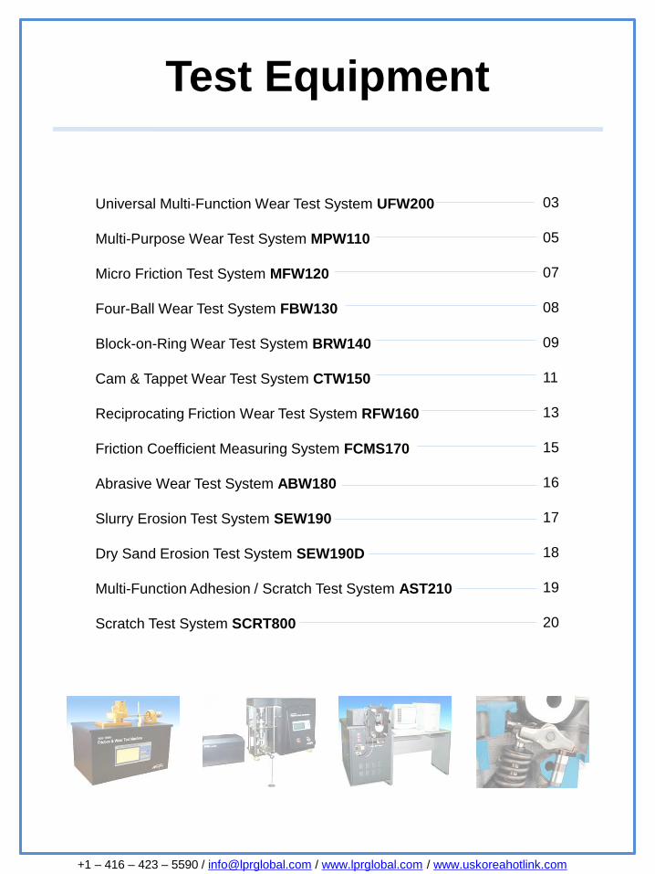
General InformationThe UFW200 system evaluates four types of friction and wear –rotation, reciprocating, Block-on-Ring, and scratch. It identifies
wear situations incurred by rotating, reciprocating, abrasiveness,
fretting, galling, and seizure. The UFW200 system is able to carry
out tests in multiple environments by controlling areas such as
temperature, humidity, pressure, etc.
The system reveals friction and wear characteristics for various
materials including metal, ceramic, compound materials, coatings,
as well as nano and bio material.
The pressure load can be configured to adjust to load applications
ranging from a light to heavy load by the use of a static load
device.
Temperature and humidity can be adjusted during testing using hot
air convection heat. The system is configured to measure wear
loss and friction coefficient in real time during wear testing and
results are simultaneously stored in a computer.
The UFW200 series performs both the module test and the friction
and wear test on one machine resulting in more reliable data.
Multi-Function Tests- Static and dynamic friction test
- Adhesive, abrasive and scratch wear test
- Multi-cycle, multi-axis fatigue wear test
- Pull-off adhesion wear test
Test Modes- Pin-on-Disc (One Pin) (ISO 7148, ASTM G99)
- Ball-on-Disc (One Ball) (ISO 7148)
- Sliding Contact Wear
- Bearing Life
- Block-on-Ring
- Scuffing Wear
- Reciprocating Motion Test
- Scratch
Universal Multi-Function Wear Test System – UFW200
4
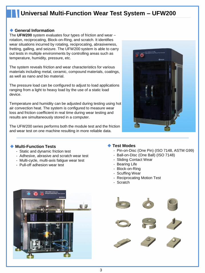
Rotation Module- Pin-on-Disc (One Pin) (ISO 7148, ASTM G99)
- Ball-on-Disc (One Ball) (ISO 7148)
- Four-Ball
Pin/Ball-on-Disc Test- Upper Pin or Ball Specimen
- Stationary or automatic positioning on disc
radius
- RPM 0 – 1,000rpm
- Automatic Radius Positioning
- Range: 70mm
- Resolution: 0.1mm
Linear Reciprocation Module- Upper Pin/Ball/Block
- Distance: 0 – 50mm
- Reciprocating Frequency: 0.1 – 50 Hz
- Reciprocating Stroke: 0.1 – 25mm
Wear and Fretting Tests- Upper Pin/Ball/Block Specimen
- Stationary or automatic positioning on disc radius
- Automatic Radius Positioning
- Range: 50mm
- Resolution: 1㎛
Engine Tests- Upper piston ring: stationary
- Lower cylinder liner: reciprocating
Block-on-Ring Test Module- Upper Block: 5mm x 15mm x 10mm
- Lower Ring: dia. 20-70 mm
- Rotation Speed: 1 – 1,000 rpm
Block/Pin/Ball-on-Ring Test- Upper Pin: dia. 3 – 10 mm
- Flat, spherical or conical end
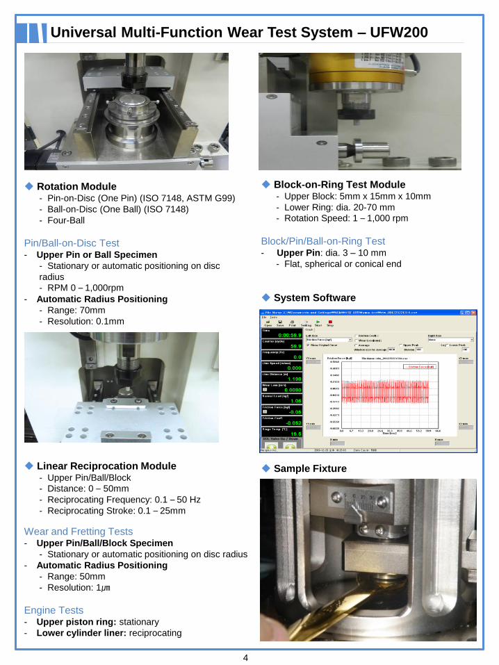
System Software
Sample Fixture

Multi-Purpose Wear Test System – MPW110
5
General InformationThe MPW110 system is a Macro Scale Wear Tester and while
used to primarily perform Pin-on-Disc or Ball-on-Disc tests, it
can also be used to perform Thrust Washer, Four-Ball, Ball-
on-Flat, and oscillating tests as well. The temperature and
humidity within the test environment is set prior to the test and
can even be adjusted during testing. Temperature is precisely
controlled up to ±1° using PID control.
The equipment is manufactured to evaluate the friction and
wear characteristics for various materials including metal,
ceramic, composites, coatings, nano and bio materials.
To adjust the load application range from light load to heavy
load, the pressure load is configured by a two-stage lever.
The system is configured to measure wear loss and friction
coefficient in real time during testing and the results can be
simultaneously stored in a computer.
Control Parameters- Rotation Speed (rpm)
- Load (kgf)
- Temperature (°)
- Humidity (%)
- Time (sec)
- Cycle
- Lubricant Chamber Temperature
- Microsoft Windows XP Compatible
- User-friendly screen configuration
- Average and Peak Curve Readings
- Real Time Data Display and Storage
- Can modify parameters during test
Recorded Parameters- Rotation speed (rpm)
- Friction force (N)
- Sliding speed (m/sec)
- Wear loss (㎛)
- Sliding distance (m)
- Temperature (stage, specimen surface: °)
- Test time (sec)
- Test cycle (cycle)
- Friction coefficient (µ)
Standard MPW110 Configuration
High Temperature Furnace Type
6
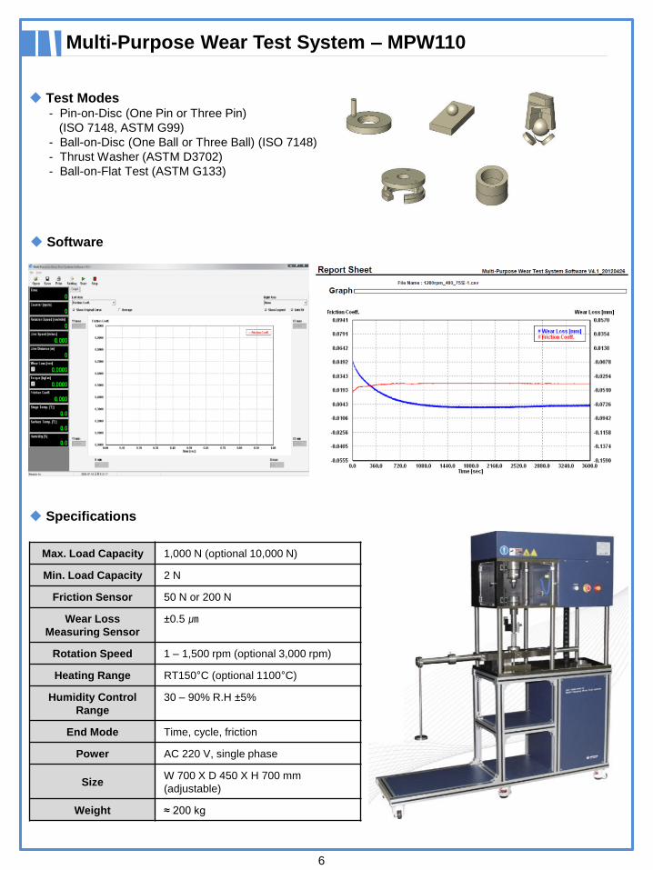
Multi-Purpose Wear Test System – MPW110
Test Modes- Pin-on-Disc (One Pin or Three Pin)
(ISO 7148, ASTM G99)
- Ball-on-Disc (One Ball or Three Ball) (ISO 7148)
- Thrust Washer (ASTM D3702)
- Ball-on-Flat Test (ASTM G133)
Specifications
Max. Load Capacity 1,000 N (optional 10,000 N)
Min. Load Capacity 2 N
Friction Sensor 50 N or 200 N
Wear Loss
Measuring Sensor
±0.5 ㎛
Rotation Speed 1 – 1,500 rpm (optional 3,000 rpm)
Heating Range RT150°C (optional 1100°C)
Humidity Control
Range
30 – 90% R.H ±5%
End Mode Time, cycle, friction
Power AC 220 V, single phase
SizeW 700 X D 450 X H 700 mm
(adjustable)
Weight ≈ 200 kg
Software
Micro Friction Test System – MFW120
7
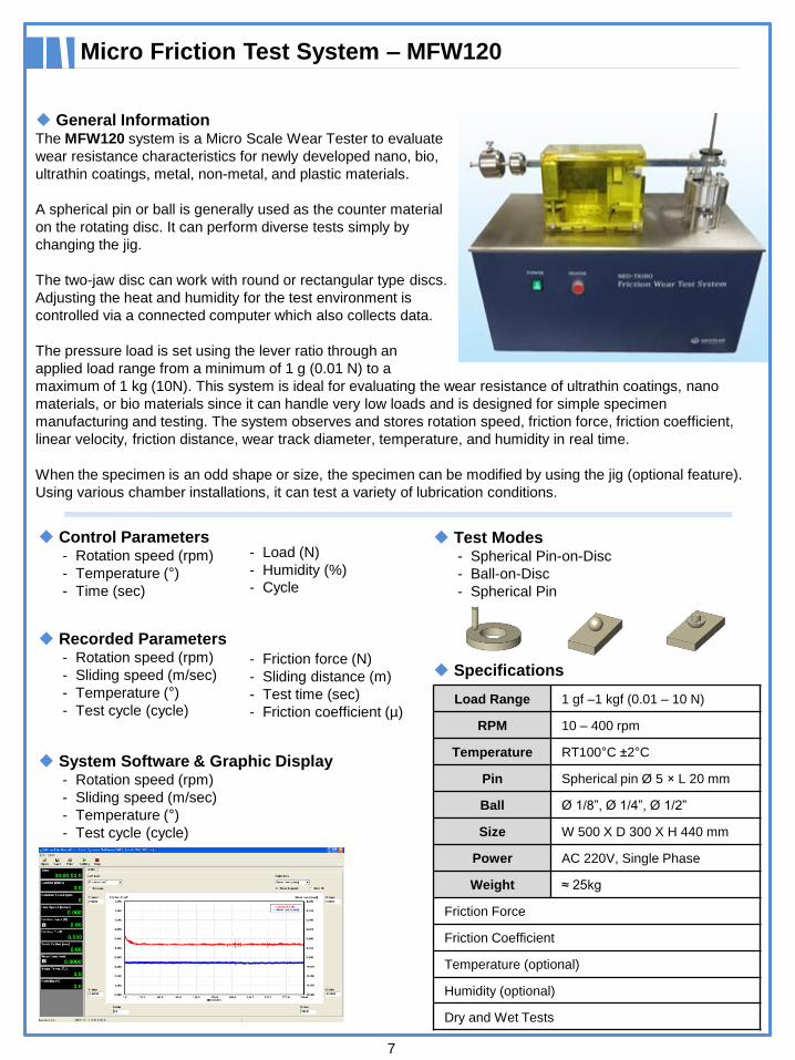
General InformationThe MFW120 system is a Micro Scale Wear Tester to evaluate
wear resistance characteristics for newly developed nano, bio,
ultrathin coatings, metal, non-metal, and plastic materials.
A spherical pin or ball is generally used as the counter material
on the rotating disc. It can perform diverse tests simply by
changing the jig.
The two-jaw disc can work with round or rectangular type discs.
Adjusting the heat and humidity for the test environment is
controlled via a connected computer which also collects data.
The pressure load is set using the lever ratio through an
applied load range from a minimum of 1 g (0.01 N) to a
maximum of 1 kg (10N). This system is ideal for evaluating the wear resistance of ultrathin coatings, nano
materials, or bio materials since it can handle very low loads and is designed for simple specimen
manufacturing and testing. The system observes and stores rotation speed, friction force, friction coefficient,
linear velocity, friction distance, wear track diameter, temperature, and humidity in real time.
When the specimen is an odd shape or size, the specimen can be modified by using the jig (optional feature).
Using various chamber installations, it can test a variety of lubrication conditions.
Control Parameters- Rotation speed (rpm)
- Temperature (°)
- Time (sec)
- Load (N)
- Humidity (%)
- Cycle
Recorded Parameters- Rotation speed (rpm)
- Sliding speed (m/sec)
- Temperature (°)
- Test cycle (cycle)
- Friction force (N)
- Sliding distance (m)
- Test time (sec)
- Friction coefficient (µ)
System Software & Graphic Display- Rotation speed (rpm)
- Sliding speed (m/sec)
- Temperature (°)
- Test cycle (cycle)
Test Modes- Spherical Pin-on-Disc
- Ball-on-Disc
- Spherical Pin
Specifications
Load Range 1 gf –1 kgf (0.01 – 10 N)
RPM 10 – 400 rpm
Temperature RT100°C ±2°C
Pin Spherical pin Ø 5 × L 20 mm
Ball Ø 1/8”, Ø 1/4”, Ø 1/2”
Size W 500 X D 300 X H 440 mm
Power AC 220V, Single Phase
Weight ≈ 25kg
Friction Force
Friction Coefficient
Temperature (optional)
Humidity (optional)
Dry and Wet Tests
Four-Ball Wear Test System – FBW130
8
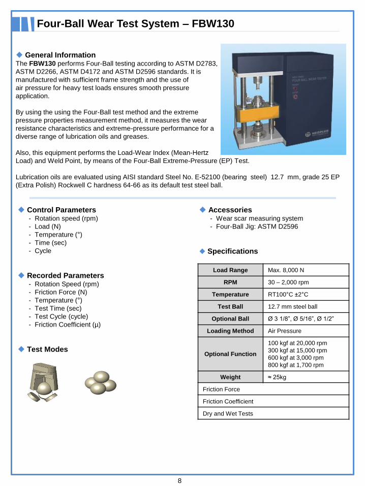
General InformationThe FBW130 performs Four-Ball testing according to ASTM D2783,
ASTM D2266, ASTM D4172 and ASTM D2596 standards. It is
manufactured with sufficient frame strength and the use of
air pressure for heavy test loads ensures smooth pressure
application.
By using the using the Four-Ball test method and the extreme
pressure properties measurement method, it measures the wear
resistance characteristics and extreme-pressure performance for a
diverse range of lubrication oils and greases.
Also, this equipment performs the Load-Wear Index (Mean-Hertz
Load) and Weld Point, by means of the Four-Ball Extreme-Pressure (EP) Test.
Lubrication oils are evaluated using AISI standard Steel No. E-52100 (bearing steel) 12.7 mm, grade 25 EP
(Extra Polish) Rockwell C hardness 64-66 as its default test steel ball.
Control Parameters- Rotation speed (rpm)
- Load (N)
- Temperature (°)
- Time (sec)
- Cycle
Recorded Parameters- Rotation Speed (rpm)
- Friction Force (N)
- Temperature (°)
- Test Time (sec)
- Test Cycle (cycle)
- Friction Coefficient (µ)
Test Modes
Accessories- Wear scar measuring system
- Four-Ball Jig: ASTM D2596
Specifications
Load Range Max. 8,000 N
RPM 30 – 2,000 rpm
Temperature RT100°C ±2°C
Test Ball 12.7 mm steel ball
Optional Ball Ø 3 1/8”, Ø 5/16”, Ø 1/2”
Loading Method Air Pressure
Optional Function
100 kgf at 20,000 rpm
300 kgf at 15,000 rpm
600 kgf at 3,000 rpm
800 kgf at 1,700 rpm
Weight ≈ 25kg
Friction Force
Friction Coefficient
Dry and Wet Tests
Block-on-Ring Wear Test System – BRW140
9
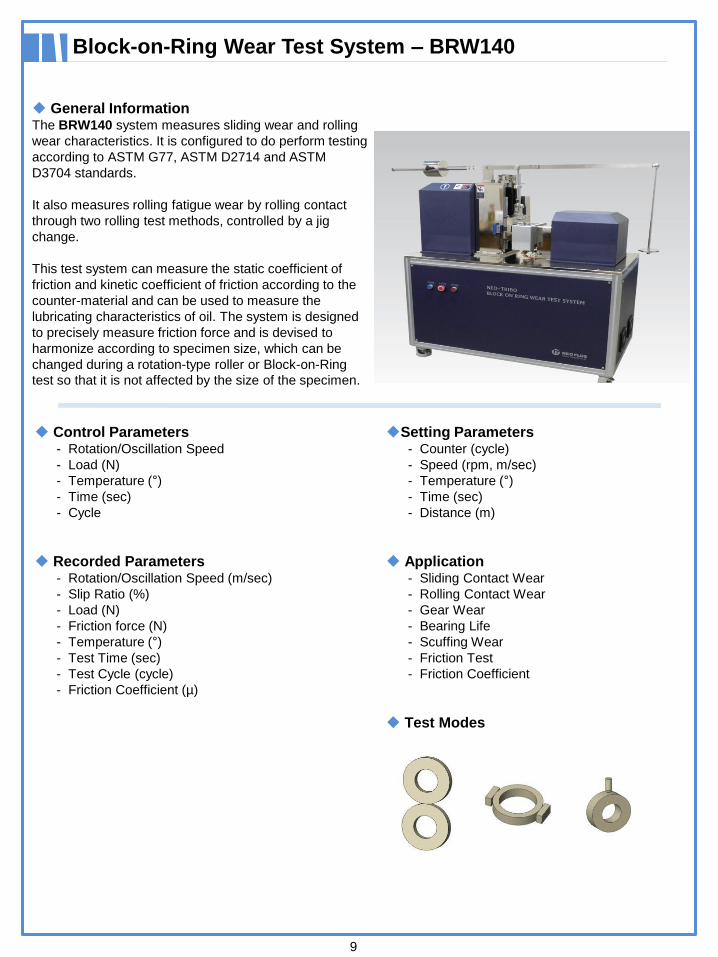
General InformationThe BRW140 system measures sliding wear and rolling
wear characteristics. It is configured to do perform testing
according to ASTM G77, ASTM D2714 and ASTM
D3704 standards.
It also measures rolling fatigue wear by rolling contact
through two rolling test methods, controlled by a jig
change.
This test system can measure the static coefficient of
friction and kinetic coefficient of friction according to the
counter-material and can be used to measure the
lubricating characteristics of oil. The system is designed
to precisely measure friction force and is devised to
harmonize according to specimen size, which can be
changed during a rotation-type roller or Block-on-Ring
test so that it is not affected by the size of the specimen.
Control Parameters- Rotation/Oscillation Speed
- Load (N)
- Temperature (°)
- Time (sec)
- Cycle
Recorded Parameters- Rotation/Oscillation Speed (m/sec)
- Slip Ratio (%)
- Load (N)
- Friction force (N)
- Temperature (°)
- Test Time (sec)
- Test Cycle (cycle)
- Friction Coefficient (µ)
Setting Parameters- Counter (cycle)
- Speed (rpm, m/sec)
- Temperature (°)
- Time (sec)
- Distance (m)
Application- Sliding Contact Wear
- Rolling Contact Wear
- Gear Wear
- Bearing Life
- Scuffing Wear
- Friction Test
- Friction Coefficient
Test Modes
10
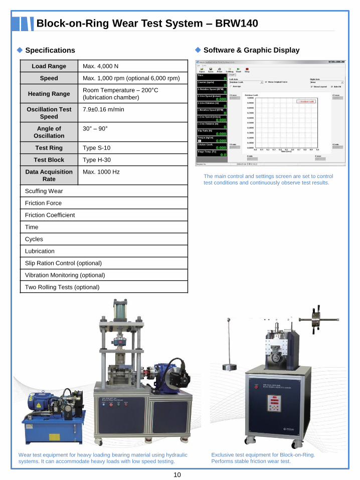
Specifications
Block-on-Ring Wear Test System – BRW140
Load Range Max. 4,000 N
Speed Max. 1,000 rpm (optional 6,000 rpm)
Heating RangeRoom Temperature – 200°C
(lubrication chamber)
Oscillation Test
Speed
7.9±0.16 m/min
Angle of
Oscillation
30° – 90°
Test Ring Type S-10
Test Block Type H-30
Data Acquisition
Rate
Max. 1000 Hz
Scuffing Wear
Friction Force
Friction Coefficient
Time
Cycles
Lubrication
Slip Ration Control (optional)
Vibration Monitoring (optional)
Two Rolling Tests (optional)
Wear test equipment for heavy loading bearing material using hydraulic
systems. It can accommodate heavy loads with low speed testing.
Exclusive test equipment for Block-on-Ring.
Performs stable friction wear test.
The main control and settings screen are set to control
test conditions and continuously observe test results.
Software & Graphic Display
Cam & Tappet Wear Test System – CTW150
11
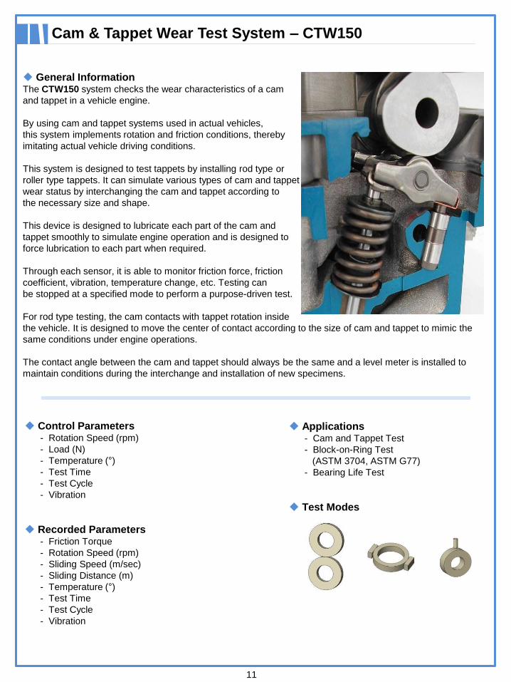
General InformationThe CTW150 system checks the wear characteristics of a cam
and tappet in a vehicle engine.
By using cam and tappet systems used in actual vehicles,
this system implements rotation and friction conditions, thereby
imitating actual vehicle driving conditions.
This system is designed to test tappets by installing rod type or
roller type tappets. It can simulate various types of cam and tappet
wear status by interchanging the cam and tappet according to
the necessary size and shape.
This device is designed to lubricate each part of the cam and
tappet smoothly to simulate engine operation and is designed to
force lubrication to each part when required.
Through each sensor, it is able to monitor friction force, friction
coefficient, vibration, temperature change, etc. Testing can
be stopped at a specified mode to perform a purpose-driven test.
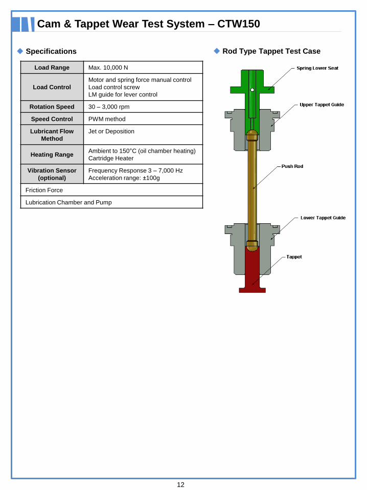
For rod type testing, the cam contacts with tappet rotation inside
the vehicle. It is designed to move the center of contact according to the size of cam and tappet to mimic the
same conditions under engine operations.
The contact angle between the cam and tappet should always be the same and a level meter is installed to
maintain conditions during the interchange and installation of new specimens.
Control Parameters- Rotation Speed (rpm)
- Load (N)
- Temperature (°)
- Test Time
- Test Cycle
- Vibration
Recorded Parameters- Friction Torque
- Rotation Speed (rpm)
- Sliding Speed (m/sec)
- Sliding Distance (m)
- Temperature (°)
- Test Time
- Test Cycle
- Vibration
Applications- Cam and Tappet Test
- Block-on-Ring Test
(ASTM 3704, ASTM G77)
- Bearing Life Test
Test Modes
12
Specifications
Cam & Tappet Wear Test System – CTW150
Load Range Max. 10,000 N
Load Control
Motor and spring force manual control
Load control screw
LM guide for lever control
Rotation Speed 30 – 3,000 rpm
Speed Control PWM method
Lubricant Flow
Method
Jet or Deposition
Heating RangeAmbient to 150°C (oil chamber heating)
Cartridge Heater
Vibration Sensor
(optional)
Frequency Response 3 – 7,000 Hz
Acceleration range: ±100g
Friction Force
Lubrication Chamber and Pump
Rod Type Tappet Test Case
Reciprocating Friction Wear Test System – RFW160
13
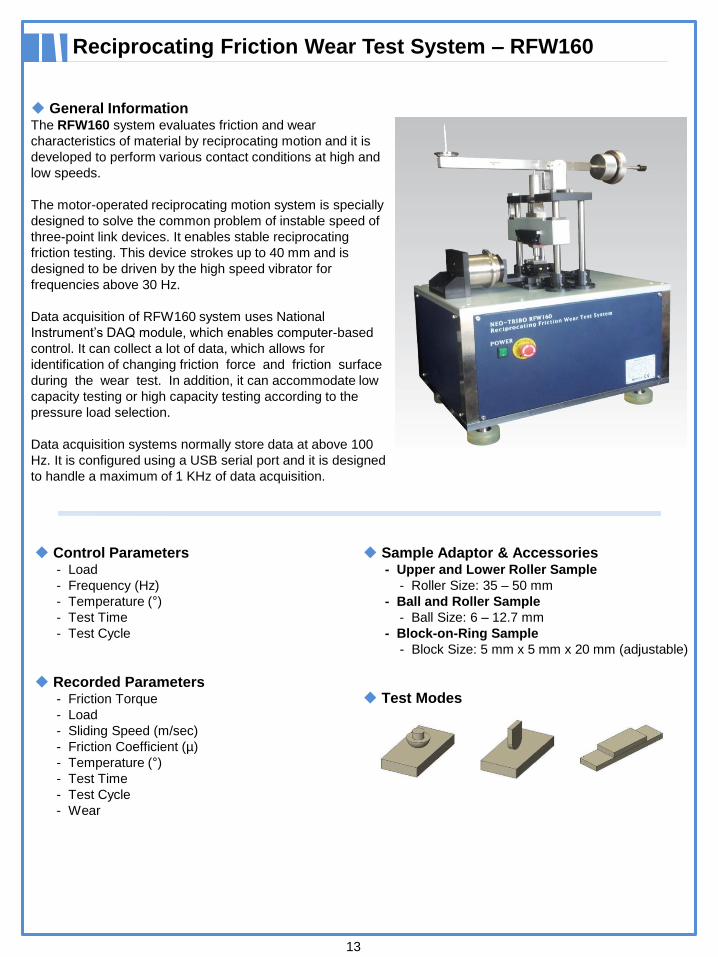
General InformationThe RFW160 system evaluates friction and wear
characteristics of material by reciprocating motion and it is
developed to perform various contact conditions at high and
low speeds.
The motor-operated reciprocating motion system is specially
designed to solve the common problem of instable speed of
three-point link devices. It enables stable reciprocating
friction testing. This device strokes up to 40 mm and is
designed to be driven by the high speed vibrator for
frequencies above 30 Hz.
Data acquisition of RFW160 system uses National
Instrument’s DAQ module, which enables computer-based
control. It can collect a lot of data, which allows for
identification of changing friction force and friction surface
during the wear test. In addition, it can accommodate low
capacity testing or high capacity testing according to the
pressure load selection.
Data acquisition systems normally store data at above 100
Hz. It is configured using a USB serial port and it is designed
to handle a maximum of 1 KHz of data acquisition.
Control Parameters- Load
- Frequency (Hz)
- Temperature (°)
- Test Time
- Test Cycle
Recorded Parameters- Friction Torque
- Load
- Sliding Speed (m/sec)
- Friction Coefficient (µ)
- Temperature (°)
- Test Time
- Test Cycle
- Wear
Sample Adaptor & Accessories- Upper and Lower Roller Sample
- Roller Size: 35 – 50 mm
- Ball and Roller Sample
- Ball Size: 6 – 12.7 mm
- Block-on-Ring Sample
- Block Size: 5 mm x 5 mm x 20 mm (adjustable)
Test Modes

14
Specifications
Reciprocating Friction Wear Test System – RFW160
Load Range 2.5 – 50 N
Load Control Motor and Spring Force Control
Temperature
Range
Ambient – 150°C
Heating Power
Cartridge
400 W
Temperature
Sensor
K-type Thermocouple
Frequency Range 1 – 30 Hz or 30+ Hz (optional)
Stroke Max. 40mm
Friction
Transducer
Piezo Electric Type
Place Specimen 80 mm x 30 mm x 5 mm
Software- Neo-Plus Sequence Control
- Data Acquisition Software
Area Contact
Line Contact
Point Contact
Interface Neo-Plus Serial Link Interface Module
Software
Operating system is designed to be user-friendly.
The static load device enables the load weight to be
controlled and fixed. The Hz load controls the sine wave.
Friction Coefficient Measuring System – FCMS170
15
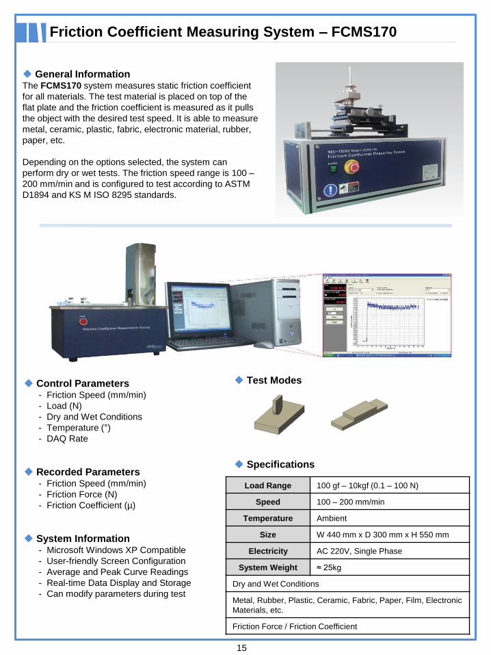
General InformationThe FCMS170 system measures static friction coefficient
for all materials. The test material is placed on top of the
flat plate and the friction coefficient is measured as it pulls
the object with the desired test speed. It is able to measure
metal, ceramic, plastic, fabric, electronic material, rubber,
paper, etc.
Depending on the options selected, the system can
perform dry or wet tests. The friction speed range is 100 –
200 mm/min and is configured to test according to ASTM
D1894 and KS M ISO 8295 standards.
Control Parameters- Friction Speed (mm/min)
- Load (N)
- Dry and Wet Conditions
- Temperature (°)
- DAQ Rate
Recorded Parameters- Friction Speed (mm/min)
- Friction Force (N)
- Friction Coefficient (µ)
System Information- Microsoft Windows XP Compatible
- User-friendly Screen Configuration
- Average and Peak Curve Readings
- Real-time Data Display and Storage
- Can modify parameters during test
Test Modes
Specifications
Load Range 100 gf – 10kgf (0.1 – 100 N)
Speed 100 – 200 mm/min
Temperature Ambient
Size W 440 mm x D 300 mm x H 550 mm
Electricity AC 220V, Single Phase
System Weight ≈ 25kg
Dry and Wet Conditions
Metal, Rubber, Plastic, Ceramic, Fabric, Paper, Film, Electronic
Materials, etc.
Friction Force / Friction Coefficient
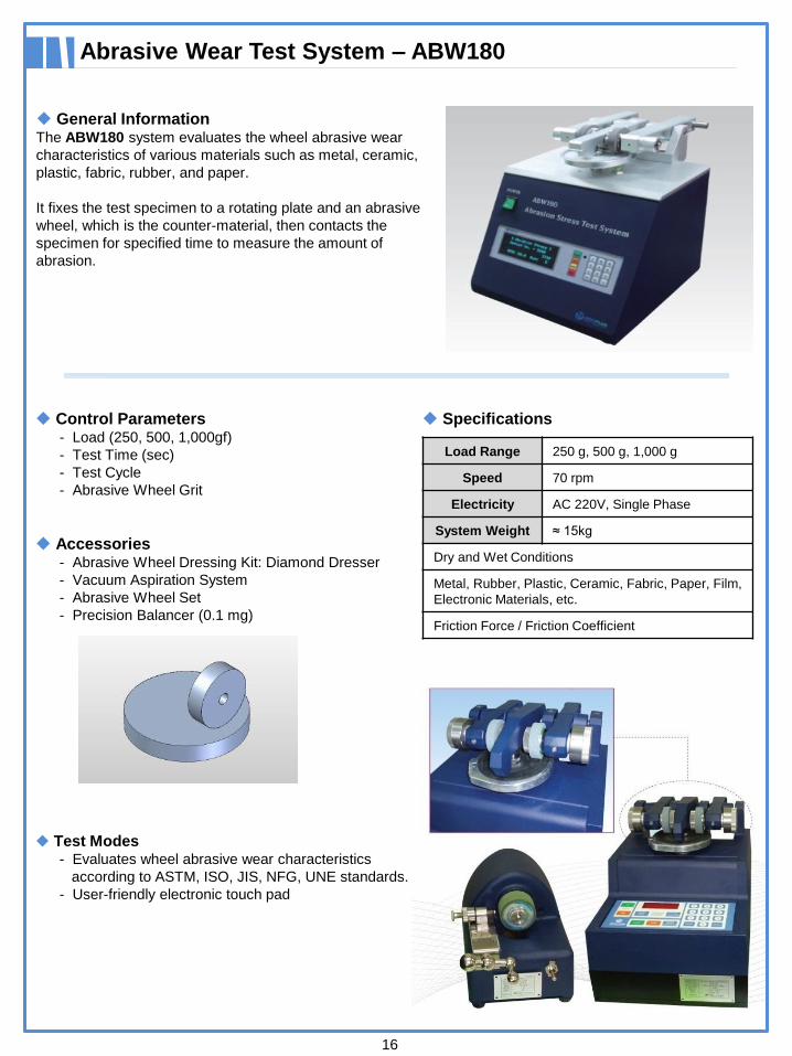
Abrasive Wear Test System – ABW180
General InformationThe ABW180 system evaluates the wheel abrasive wear
characteristics of various materials such as metal, ceramic,
plastic, fabric, rubber, and paper.
It fixes the test specimen to a rotating plate and an abrasive
wheel, which is the counter-material, then contacts the
specimen for specified time to measure the amount of
abrasion.
Control Parameters- Load (250, 500, 1,000gf)
- Test Time (sec)
- Test Cycle
- Abrasive Wheel Grit
Accessories- Abrasive Wheel Dressing Kit: Diamond Dresser
- Vacuum Aspiration System
- Abrasive Wheel Set
- Precision Balancer (0.1 mg)
Test Modes- Evaluates wheel abrasive wear characteristics
according to ASTM, ISO, JIS, NFG, UNE standards.
- User-friendly electronic touch pad
Specifications
Load Range 250 g, 500 g, 1,000 g
Speed 70 rpm
Electricity AC 220V, Single Phase
System Weight ≈ 15kg
Dry and Wet Conditions
Metal, Rubber, Plastic, Ceramic, Fabric, Paper, Film,
Electronic Materials, etc.
Friction Force / Friction Coefficient
16
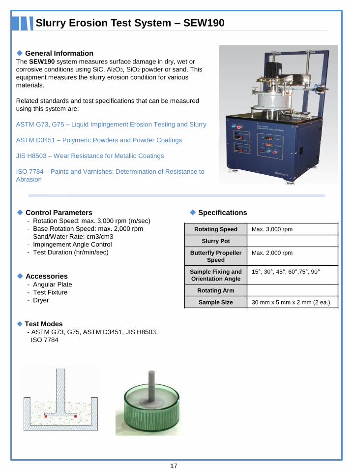
Slurry Erosion Test System – SEW190
17
General InformationThe SEW190 system measures surface damage in dry, wet or
corrosive conditions using SiC, Al2O3, SiO2 powder or sand. This
equipment measures the slurry erosion condition for various
materials.
Related standards and test specifications that can be measured
using this system are:
ASTM G73, G75 – Liquid Impingement Erosion Testing and Slurry
ASTM D3451 – Polymeric Powders and Powder Coatings
JIS H8503 – Wear Resistance for Metallic Coatings
ISO 7784 – Paints and Varnishes: Determination of Resistance to
Abrasion
Control Parameters- Rotation Speed: max. 3,000 rpm (m/sec)
- Base Rotation Speed: max. 2,000 rpm
- Sand/Water Rate: cm3/cm3
- Impingement Angle Control
- Test Duration (hr/min/sec)
Accessories- Angular Plate
- Test Fixture
- Dryer
Test Modes- ASTM G73, G75, ASTM D3451, JIS H8503,
ISO 7784
Specifications
Rotating Speed Max. 3,000 rpm
Slurry Pot
Butterfly Propeller
Speed
Max. 2,000 rpm
Sample Fixing and
Orientation Angle
15°, 30°, 45°, 60°,75°, 90°
Rotating Arm
Sample Size 30 mm x 5 mm x 2 mm (2 ea.)
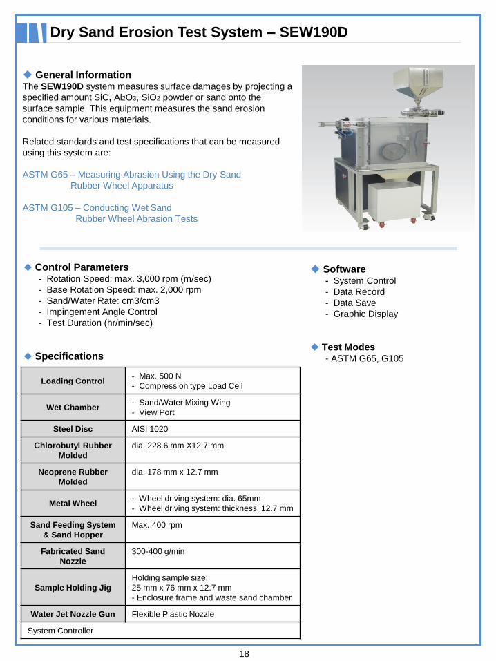
Dry Sand Erosion Test System – SEW190D
18
General InformationThe SEW190D system measures surface damages by projecting a
specified amount SiC, Al2O3, SiO2 powder or sand onto the
surface sample. This equipment measures the sand erosion
conditions for various materials.
Related standards and test specifications that can be measured
using this system are:
ASTM G65 – Measuring Abrasion Using the Dry Sand
Rubber Wheel Apparatus
ASTM G105 – Conducting Wet Sand
Rubber Wheel Abrasion Tests
Software- System Control
- Data Record
- Data Save
- Graphic Display
Test Modes- ASTM G65, G105
Loading Control- Max. 500 N
- Compression type Load Cell
Wet Chamber- Sand/Water Mixing Wing
- View Port
Steel Disc AISI 1020
Chlorobutyl Rubber
Molded
dia. 228.6 mm X12.7 mm
Neoprene Rubber
Molded
dia. 178 mm x 12.7 mm
Metal Wheel- Wheel driving system: dia. 65mm
- Wheel driving system: thickness. 12.7 mm
Sand Feeding System
& Sand Hopper
Max. 400 rpm
Fabricated Sand
Nozzle
300-400 g/min
Sample Holding Jig
Holding sample size:
25 mm x 76 mm x 12.7 mm
- Enclosure frame and waste sand chamber
Water Jet Nozzle Gun Flexible Plastic Nozzle
System Controller
Control Parameters- Rotation Speed: max. 3,000 rpm (m/sec)
- Base Rotation Speed: max. 2,000 rpm
- Sand/Water Rate: cm3/cm3
- Impingement Angle Control
- Test Duration (hr/min/sec)
Specifications
Multi-Function Adhesion/Scratch Test System – AST210
19
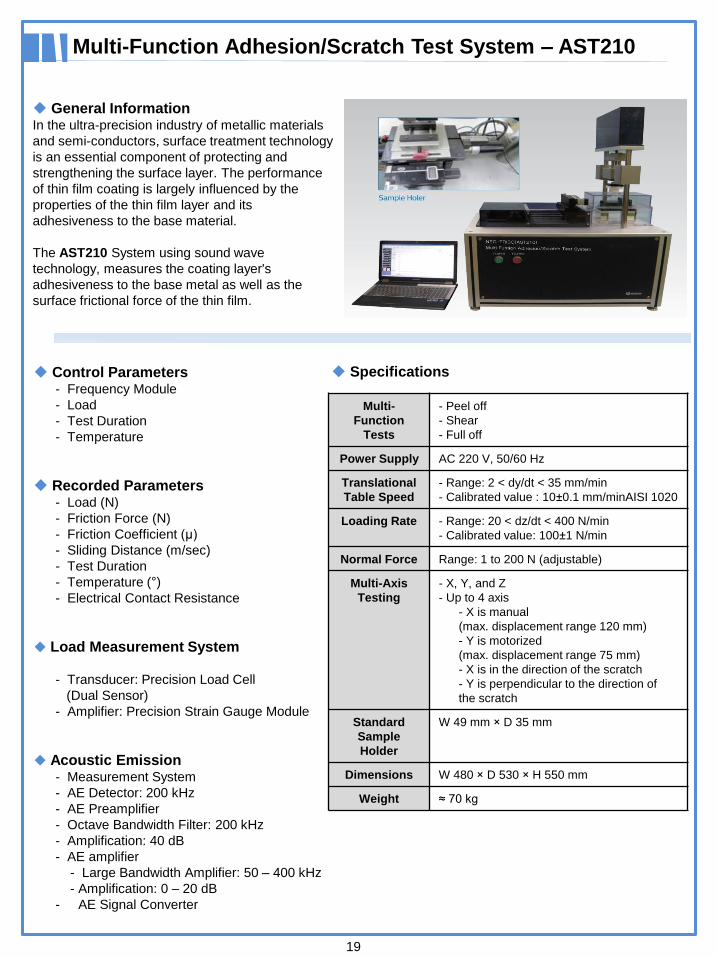
General InformationIn the ultra-precision industry of metallic materials
and semi-conductors, surface treatment technology
is an essential component of protecting and
strengthening the surface layer. The performance
of thin film coating is largely influenced by the
properties of the thin film layer and its
adhesiveness to the base material.
The AST210 System using sound wave
technology, measures the coating layer's
adhesiveness to the base metal as well as the
surface frictional force of the thin film.
Control Parameters- Frequency Module
- Load
- Test Duration
- Temperature
Recorded Parameters- Load (N)
- Friction Force (N)
- Friction Coefficient (μ)
- Sliding Distance (m/sec)
- Test Duration
- Temperature (°)
- Electrical Contact Resistance
Load Measurement System
- Transducer: Precision Load Cell
(Dual Sensor)
- Amplifier: Precision Strain Gauge Module
Acoustic Emission- Measurement System
- AE Detector: 200 kHz
- AE Preamplifier
- Octave Bandwidth Filter: 200 kHz
- Amplification: 40 dB
- AE amplifier
- Large Bandwidth Amplifier: 50 – 400 kHz
- Amplification: 0 – 20 dB
- AE Signal Converter
Specifications
Multi-
Function
Tests
- Peel off
- Shear
- Full off
Power Supply AC 220 V, 50/60 Hz
Translational
Table Speed
- Range: 2 < dy/dt < 35 mm/min
- Calibrated value : 10±0.1 mm/minAISI 1020
Loading Rate - Range: 20 < dz/dt < 400 N/min
- Calibrated value: 100±1 N/min
Normal Force Range: 1 to 200 N (adjustable)
Multi-Axis
Testing
- X, Y, and Z
- Up to 4 axis
- X is manual
(max. displacement range 120 mm)
- Y is motorized
(max. displacement range 75 mm)
- X is in the direction of the scratch
- Y is perpendicular to the direction of
the scratch
Standard
Sample
Holder
W 49 mm × D 35 mm
Dimensions W 480 × D 530 × H 550 mm
Weight ≈ 70 kg
Scratch Test System – SCRT800
20
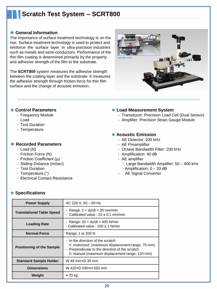
General InformationThe importance of surface treatment technology is on the
rise. Surface treatment technology is used to protect and
reinforce the surface layer in ultra-precision industries
such as metals and semi-conductors. Performance of the
thin film coating is determined primarily by the property
and adhesive strength of the film to the substrate.
The SCRT800 system measures the adhesive strength
between the coating layer and the substrate. It measures
the adhesive strength through friction force for thin film
surface and the change of acoustic emission.
Load Measurement System- Transducer: Precision Load Cell (Dual Sensor)
- Amplifier: Precision Strain Gauge Module
Acoustic Emission- AE Detector: 200 kHz
- AE Preamplifier
- Octave Bandwidth Filter: 200 kHz
- Amplification: 40 dB
- AE amplifier
- Large Bandwidth Amplifier: 50 – 400 kHz
- Amplification: 0 – 20 dB
- AE Signal Converter
Power Supply AC 220 V, 50 – 60 Hz
Translational Table Speed - Range: 2 < dy/dt < 35 mm/min
- Calibrated value : 10 ± 0.1 mm/min
Loading Rate - Range: 20 < dz/dt < 400 N/min
- Calibrated value : 100 ± 1 N/min
Normal Force Range: 1 to 200 N
Positioning of the Sample
- In the direction of the scratch
Y: motorized (maximum displacement range: 75 mm)
- Perpendicular to the direction of the scratch
X: manual (maximum displacement range: 120 mm)
Standard Sample Holder W 49 mm×D 35 mm
Dimensions W 420×D 530×H 550 mm
Weight ≈ 70 kg
Control Parameters- Frequency Module
- Load
- Test Duration
- Temperature
Recorded Parameters- Load (N)
- Friction Force (N)
- Friction Coefficient (μ)
- Sliding Distance (m/sec)
- Test Duration
- Temperature (°)
- Electrical Contact Resistance
Specifications

LPR Global Inc.344 Bloor Street W., Unit 607, Toronto, ON Canada M5S 3A7
www.lprglobal.com / www.uskoreahotlink.com
TEL: +1 – 416 – 423 – 5590
E-mail: [email protected]