Embed Size (px)
Citation preview
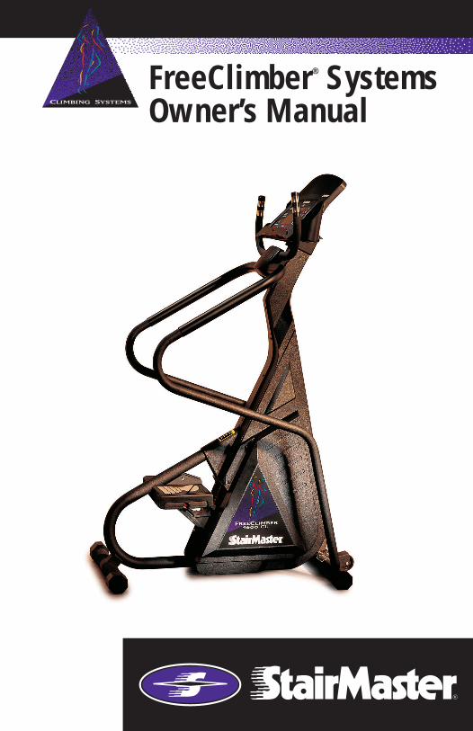
FreeClimber® SystemsOwner’s Manual

© 1997 StairMaster Sports/Medical Products, Inc., StairMaster and FreeClimber are registered trademarks or trademarks of StairMaster Sports/Medical Products, Inc. in the United States
and /or other countries. All other trademarks are trademarks of their respective companies.
P/N 22569-E
Printed in the United States.©1997 StairMaster® Sports/Medical Products, Inc.
All rights reserved.
Corporate Headquarters12421 Willows Road N.E., Suite 100
Kirkland, WA 98034
(800) 635-2936(425) 823-1825
Fax (425) 823-9490www.stairmaster.com
Page iii

Page iv
10 REASONS WHY MORE HEALTH AND FITNESSFACILITIES CHOOSE STAIRMASTER® EQUIPMENT
OUTSTANDING QUALITYEquipment you can depend upon, week after week, for heavy commercial use –instead of a sign that says "out of order."
EXCEPTIONAL PERFORMANCEGenerates exceptional customer satisfaction – allowing you to retain existingclub members and attract new ones.
IMMEDIATE CUSTOMER RECOGNITIONAn excellent first impression is critical to attracting new club members to yourfacility. The StairMaster name on your equipment reinforces your club's reputa-tion for quality and effectiveness.
NATIONAL SALES SUPPORTStairMaster is one of the few organizations that maintains its own fully staffednational sales organization. These individuals will bend over backwards to makesure you are satisfied.
FACTORY-TRAINED SERVICE NETWORKThe StairMaster service staff is on call to quickly address any productconcerns. Service is just a toll-free call away.
FACTORY DIRECT PRICESNo warehousing fee. No retail markup. StairMaster sells directly to you for thebest prices available.
AFFORDABLE LEASING PROGRAMWe help you make the most of your money, with several types of leasingprograms available.
FACILITY PLANNINGCordless units. Space-efficient designs. Exciting facility layout plans. Our staffworks closely with you to maximize the equipment layout of your club or fitnessarea.
PRE-ASSEMBLED DELIVERYNo set-up, no hassle.
MARKETING SUPPORTLots of sizzle – with StairMaster product catalogs, posters, promotional kits, andseasonal promotions.
Page v
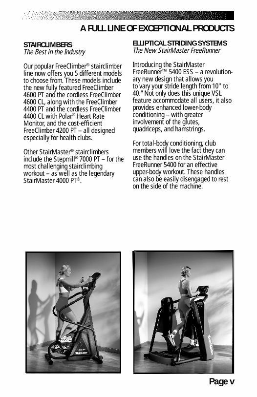
A FULL LINE OF EXCEPTIONAL PRODUCTS
STAIRCLIMBERSThe Best in the Industry
Our popular FreeClimber® stairclimberline now offers you 5 different modelsto choose from. These models includethe new fully featured FreeClimber4600 PT and the cordless FreeClimber4600 CL, along with the FreeClimber4400 PT and the cordless FreeClimber4400 CL with Polar® Heart RateMonitor, and the cost-efficientFreeClimber 4200 PT – all designedespecially for health clubs.
Other StairMaster® stairclimbersinclude the Stepmill® 7000 PT – for themost challenging stairclimbingworkout – as well as the legendaryStairMaster 4000 PT®.
ELLIPTICAL STRIDING SYSTEMSThe New StairMaster FreeRunner
Introducing the StairMasterFreeRunner™ 5400 ESS – a revolution-ary new design that allows youto vary your stride length from 10'’ to40." Not only does this unique VSLfeature accommodate all users, it alsoprovides enhanced lower-bodyconditioning – with greaterinvolvement of the glutes,quadriceps, and hamstrings.
For total-body conditioning, clubmembers will love the fact they canuse the handles on the StairMasterFreeRunner 5400 for an effectiveupper-body workout. These handlescan also be easily disengaged to reston the side of the machine.
Page vi
A FULL LINE OF EXCEPTIONAL PRODUCTS
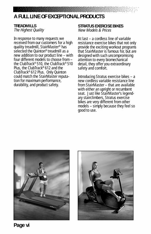
TREADMILLSThe Highest Quality
In response to many requests wereceived from our customers for a highquality treadmill, StairMaster® hasselected the Quinton® treadmill as anew addition to our product line – withfour different models to choose from –the ClubTrack® 510, the ClubTrack® 510Plus, the ClubTrack® 612 and theClubTrack® 612 Plus. Only Quintoncould match the StairMaster reputa-tion for maximum performance,durability, and product safety.
STRATUS EXERCISE BIKESNew Models & Prices
At last – a cordless line of variableresistance exercise bikes that not onlyprovide the exciting workout programsthat StairMaster is famous for, but aredesigned with such uncompromisingattention to every biomechanicaldetail, they offer you extraordinarysafety and comfort.
Introducing Stratus exercise bikes – anew cordless variable resistance linefrom StairMaster – that are availablewith either an upright or recumbentseat. Just like StairMaster's legend-ary stairclimbers, Stratus exercisebikes are very different from othermodels – simply because they feel sogood to use.
Page vii
A FULL LINE OF EXCEPTIONAL PRODUCTS
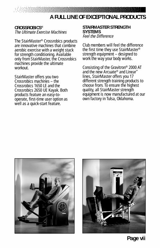
CROSSROBICS®
The Ultimate Exercise Machines
The StairMaster® Crossrobics productsare innovative machines that combineaerobic exercise with a weight stackfor strength conditioning. Availableonly from StairMaster, the Crossrobicsmachines provide the ultimateworkout.
StairMaster offers you twoCrossrobics machines – theCrossrobics 1650 LE and theCrossrobics 2650 UE Kayak. Bothproducts feature an easy-to-operate, first-time user option aswell as a quick-start feature.
STAIRMASTER STRENGTHSYSTEMSFeel the Difference
Club members will feel the differencethe first time they use StairMaster®
strength equipment – designed towork the way your body works.
Consisting of the Gravitron® 2000 ATand the new Arcuate® and Linear™
lines, StairMaster offers you 17different strength training products tochoose from. To ensure the highestquality, all StairMaster strengthequipment is now manufactured at ourown factory in Tulsa, Oklahoma.

Page viii
WARRANTYThis is to certify that the StairMaster® FreeClimber® exercise system is warrantedby StairMaster Sports/Medical Products, Inc. to be free of all defects in materialsand workmanship. This warranty does not apply to any defect caused by negligence,misuse, accident, alteration, improper maintenance, or an “act of God”. This warrantyis non-transferable from the original owner.
If, within three years from the date of purchase, any part of the StairMasterFreeClimber exercise system should fail to operate properly (except any accessories or thebattery on the 4600 CL and the 4400 CL), contact our Customer Service Department toreport the problem When calling, please be prepared to provide the customer servicerepresentative with the following information:
• Your name, customer number, shipping address, and telephone number• The model and serial number of the inoperable machine• The date(s) of purchase for the inoperable machine(s)• Your billing address
This information will ensure that you are the only one ordering parts under yourwarranty protection. If warranty replacement parts are shipped to you, you may berequired to return the inoperable part. To facilitate this process, the following policy hasbeen established:
• Please call our Customer Service Department to receive a returngoods authorization prior to shipment.• StairMaster Sports/Medical Products, Inc. will incur all freight
charges for warranty parts ordered for a machine that is less than 45days old. The parts will be shipped to you via an overnight courier.*
• You are responsible for freight charges on warranty parts formachines that are more than 45 days old. You will not be responsiblefor the return shipment of the inoperable parts.
• Some inoperable warranty parts must be promptly returned to ourCustomer Service Department. We will pay the shipping cost for theinoperable warranty parts. Detailed instructions are included witheach warranty replacement part.
StairMaster Sports/Medical Products, Inc. neither makes, assumes norauthorizes any representative or other person to make or assume for us, any otherwarranty whatsoever, whether expressed or implied, in connection with the sale, service,or shipment of our products. We reserve the right to make changes and improvements inour products without incurring any obligation to similarly alter products previouslypurchased. In order to maintain your product warranty and to ensure the safe and efficientoperation of your machine, only authorized replacement parts can be used. This warrantyis void if parts other than those provided by StairMaster Sports/Medical Products, Inc. areused.
* Note: Aerosol products cannot be transported via air.
Page ix
PREFACERegular use of the Stairmaster® FreeClimber® exercise system is a safe andeffective way to develop aerobic fitness while conditioning the major musclesof the lower body. In order to get the best results, and to keep your machine inpeak operating condition, you should carefully read and follow the guidelinespresented in this manual.
WHAT IS IN THIS MANUAL?
The first part of this manual includes sections on safety, installation, operatinginstructions, and preventive maintenance. The second part contains detailedinformation on problem troubleshooting and repair procedures. An Appendix atthe end of the manual provides additional information for the owner.
Throughout this manual, console keypad keystrokes are enclosed in [ ].The names of the keys and special console operational modes are shown incapital letters. For example, your machine is ready to use when the console is inthe ATTRACT mode. Press [MANUAL] to start the MANUAL exercise program.
WHAT IS THE STAIRMASTER FREECLIMBER EXERCISE SYSTEM?
The StairMaster FreeClimber exercise systems are vertical climbing machineswith an independent step action. The independent step action, combined withthe patented pedal geometry featured on all StairMaster steppers, provides anaerobic workout equivalent to uphill running or climbing stairs, but without thehigh-impact pounding to the joints and muscles.
There are five FreeClimber models: the 4600 PT (Personal Trainer),the 4600 CL (Cord Less), the 4400 PT, the 4400 CL, and the 4200 PT. AllFreeClimbers feature the Quiet Drive transmission. The 4600 PT and the4600 CL have an adjustable tilting, full-featured console with a Light EmittingDiode (LED) display. The 4400 PT and the 4400 CL have an upright, rail-lessdesign. The 4600 PT and the 4400 PT use an external power supply that isplugged into an AC wall outlet. The 4600 CL and the 4400 CL use power gener-ated during a workout to run the electronics. The 4600 PT and 4600 CL havecontact heart rate and Polar® heart rate monitoring. The 4400 PT and the 4400 CLfeature Polar® heart rate monitoring. The 4200 PT uses an external power supplyto run a Liquid Crystal Display (LCD) console. This LCD console has less feedbackand fewer workout programs than the LED console on the 4600 PT/CL and the4400 PT/CL.
Page x
CONTENTSSAFFETY GUIDELINES ........................................................................................ 1
INTRODUCTION ................................................................................................... 3
INSTALLATION INSTRUCTIONS........................................................................ 6
BASIC OPERATING INSTRUCTIONS ................................................................ 9General Guidelines for Safe Operation ........................................................... 9Your First Workout ......................................................................................... 10
The ATTRACT Mode .............................................................................. 10Basic Instructions for First-Time Users ................................................. 104600/4400 PT/CL Console Set-Up ......................................................... 104200 PT Console Set-Up ........................................................................ 11Begin Exercising .................................................................................... 11
CONTACT HEART RATE (4600 PT/CL ONLY) ................................................... 13
POLAR® HEART RATE (4600/4400 PT/CL ONLY) ............................................. 14
FREECLIMBER 4600/4400 PT/CL CONSOLE .................................................... 15Text Bar .......................................................................................................... 16Display ........................................................................................................... 16Function Keypad ............................................................................................ 16Entertainment Keypad (4600 PT/CL) ............................................................. 18Exercise Program Keypad .............................................................................. 18The Quick Start Option .................................................................................. 19The Fit Test .................................................................................................... 19Preset Exercise Programs .............................................................................. 21
4600 PT/CL: ........................................................................................... 214400 PT/CL: ........................................................................................... 21
The Jackpot Option ....................................................................................... 22Turning the Jackpot Option On and Off ................................................. 23
Custom Exercise Programs ............................................................................ 23Programming Your Workout .................................................................. 23Using a Custom Program ....................................................................... 24
Custom Scrolling Message ........................................................................... 24Editing The Scrolling Message ..................................................................... 25Changing the Console Units and Language .................................................. 26Console Codes ............................................................................................... 26
Page xi
CONTENTS
FREECLIMBER 4200 PT CONSOLE ................................................................... 28Top Window .................................................................................................. 28
Workout Setup ...................................................................................... 28Timer ...................................................................................................... 30
Bottom Window ............................................................................................ 30Keypad ................................................................................................... 31
Quick Start Option ......................................................................................... 31
MAINTENANCE INSTRUCTIONS ................................................................... 32Helpful Hints .................................................................................................. 32Tool List ......................................................................................................... 32Maintenance Records ................................................................................... 32Initial Service ................................................................................................. 33Preventive Maintenance ............................................................................... 33
Cleaning ................................................................................................. 33Inspecting .............................................................................................. 33Lubrication ............................................................................................. 34Battery Charge ....................................................................................... 35Battery Disposal .................................................................................... 35
TROUBLESHOOTING ......................................................................................... 37General Troubleshooting Guidelines ............................................................. 37Electrical Troubleshooting ............................................................................. 37
4600/4400 PT: ........................................................................................ 37Alternator Test ................................................................................ 38Diode Test ....................................................................................... 39Resistor Test ................................................................................... 39
4600/4400 CL: ....................................................................................... 39Battery Test ..................................................................................... 39Alternator Test ................................................................................ 40Resistor Test ................................................................................... 40
4600/4400 PT/CL Console Diagnostics ................................................. 41Display Test ..................................................................................... 41Speaker Test ................................................................................... 41Keypad Test ..................................................................................... 41Speed Test ...................................................................................... 42Software Revision Level Test ......................................................... 42Contact Heart Rate Test .................................................................. 43Polar® Heart Rate Test .................................................................... 43
Page xii
Mechanical Troubleshooting ......................................................................... 45
PARTS REMOVAL AND REPLACEMENT ........................................................ 48Covers ............................................................................................................ 48
Mid Cover .............................................................................................. 48Top Cover ............................................................................................... 48Shield (4600 PT/CL ) .............................................................................. 49Bottom Cover ......................................................................................... 49
Console .......................................................................................................... 50Console Adjustment (4600 PT/CL) ................................................................. 50Poly-V and HTD Belt ...................................................................................... 50Step Chain Retainer ...................................................................................... 51Pedal Arm Return Spring ............................................................................... 51Step Chain ..................................................................................................... 52Spring Pulley .................................................................................................. 53Drive Chain .................................................................................................... 53Drive Shaft Assembly .................................................................................... 54Pedal .............................................................................................................. 56Leveling Arm.................................................................................................. 56Pedal Arm ...................................................................................................... 57Pedal Pad ....................................................................................................... 57Eccentric Hub Assembly ................................................................................ 58First Reduction Shaft Assembly .................................................................... 58Handlebar (4400 PT/CL ,4200 PT) .................................................................. 58Upper Handles (4600 PT/CL) ......................................................................... 59Side Handrails (4600 PT/CL) .......................................................................... 59Alternator ...................................................................................................... 60
GROUNDING INSTRUCTIONS ......................................................................... 61
FCC COMPLIANCE ............................................................................................. 62
APPENDICES
Canadian Doc Class B Compliance ............................................................... 62Important Phone Numbers ............................................................................ 63Battery Recycling Centers ............................................................................. 64Figures 10-30 ................................................................................................. 66
CONTENTS
Page xiii
LIST OF TABLES
Table 1. Dimensions and Specifications for the StairMaster® FreeClimber® Exercise Systems .................................. 5
Table 2. Fitness Rating Norms (METs) ........................................................... 20Table 3: Character Codes for the Scrolling Message ................................... 25Table 4. Console Codes ................................................................................. 27Table 5. Recommended Preventive Maintenance Schedule ......................... 36
LIST OF ILLUSTRATIONS
Figure 1: Major Parts - 4600 PT/CL ................................................................. 3Figure 2: Major Parts - 4400 PT/CL ................................................................. 4Figure 3: Level Adjusting End Caps ................................................................. 6Figure 4: DC Power Connector ........................................................................ 7Figure 5: Correct Exercise Posture ................................................................ 12Figure 6: 4600 PT/CL Console Diagram ......................................................... 15Figure 7: 4400 PT/CL Console Diagram ......................................................... 15Figure 8: 4200 PT Console Diagram .............................................................. 28Figure 9: Grounding System .......................................................................... 61Figure 10: Parts Needing Periodic Maintenance .......................................... 66Figure 11: Final Assembly - Left, 4600 PT ..................................................... 67Figure 12: Final Assembly - Right,4600 PT .................................................... 68Figure 13: Final Assembly - Left, 4600 CL ..................................................... 69Figure 14: Final Assembly - Right, 4600 CL ................................................... 70Figure 15: Covers - 4600 PT/CL ..................................................................... 71Figure 16: Pedal Arm Assembly & First Reduction Shaft Assembly
(4600/4400 PT/CL, 4200 PT) .......................................................... 72Figure 17: Drive Shaft Assembly & Eccentric Hub Assembly
(4600/4400 PT/CL, 4200 PT) .......................................................... 73Figure 18: Final Assembly - Left, 4400/4200 PT ........................................... 74Figure 19: Final Assembly - Right, 4400/4200 PT ......................................... 75Figure 20: Final Assembly - Left, 4400 CL .................................................... 76Figure 21: Final Assembly - Right, 4400 CL .................................................. 77Figure 22: Covers - 4400 PT/CL, 4200 PT ...................................................... 78Figure 23: Cover Removal .............................................................................. 79Figure 24: Cover fasteners ............................................................................ 80Figure 25: Drive Chain tensioning ................................................................ 81Figure 26: Belt Tension ................................................................................. 82
CONTENTS
Page 1
WHEN USING ELECTRICAL EQUIPMENT, ALWAYS FOLLOW THESE BASIC PRECAUTIONS:
IMPORTANT SAFETY INSTRUCTIONS
This symbol appearing throughout this manual meansAttention! Be Alert! Your safety is involved.
The following definitions apply to the words “Danger” and “Warning”found throughout this manual:
DANGER - Used to call attention to IMMEDIATE hazards which, if not avoided, will result in immediate, serious personal injury or loss of life.
WARNING - Used to call attention to POTENTIAL hazards that could result in personal injury or loss of life.
READ ALL INSTRUCTIONS BEFORE USING THE MACHINE.
To reduce the risk of electrical shock, always unplugthe external power supply from the AC wall outletbefore cleaning, maintaining, or repairing.
To reduce the risk of burns, electric shock, or injury topersons:
1. The external power supply should always be unplugged from the AC walloutlet before removing or installing parts. Never make adjustments orrepairs while an exercise program is in progress.
2. Close supervision is necessary whenever the machine is used by or nearchildren, invalids, or disabled persons.
3. Keep your hands away from all moving parts and keep your feet on thepedals while exercising. Do not operate the machine with the side coversremoved.
SAFETY GUIDELINES
!
DANGER!
WARNING!
Page 2
4. Use this machine only for its intended use as described in this Manual. Donot use parts, attachments, or accessories other than those provided byStairMaster® Sports/Medical Products, Inc.
5. Do not use the external power supply if it has a damaged cord or plug, if itis not working properly, if it has been dropped or damaged, or dropped intowater. Contact our Customer Service Department to arrange for the return ofdamaged parts. Refer to the Appendix for the appropriate phone number.
6. Connect the external power supply to a properly grounded AC wall outlet;refer to the “Grounding Instructions” section. Keep all cords away fromheated surfaces.
7. To disconnect the external power supply, remove the plug from the ACwall outlet.
8. Never drop or insert any object into any opening on the machine.
9. Do not operate where aerosol (spray) products are being used.
10. Always wear insulated gloves when handling batteries.
11. Do not crush, incinerate, or dismantle the battery. The electrolytecontains sulfuric acid which can cause serious damage to eyesand skin. Should this occur, flush profusely with water and seekmedical attention.
12. Do not use the machine outdoors.
The safety level given by the design of this equipment can only bemaintained when the equipment is regularly examined for damage and wear.Inoperable components shall be replaced immediately or the equipment shall beput out of use until it is repaired. Failure to follow all guidelines may compromisethe effectiveness of the exercise experience, expose yourself (and possiblyothers) to injury, and reduce the longevity of the machine. Follow all traininginstructions listed in the manual and/or on the machine. Physical injury mayresult from incorrect or excessive training.
SAVE THESE INSTRUCTIONS
SAFETY GUIDELINES
Page 3
Before leaving the manufacturing facility in Tulsa, Oklahoma, your StairMaster®
FreeClimber® exercise system was thoroughly inspected and tested to ensureproper operation. The major parts of the machine are shown in Figures 1 and 2.
Figure 1: Major Parts - 4600 PT/CL
INTRODUCTION
Page 4
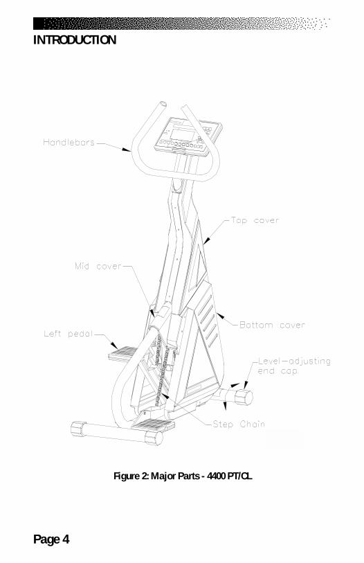
Figure 2: Major Parts - 4400 PT/CL
INTRODUCTION
Page 5
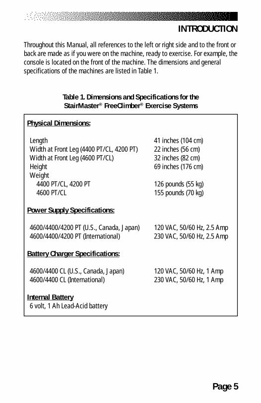
Throughout this Manual, all references to the left or right side and to the front orback are made as if you were on the machine, ready to exercise. For example, theconsole is located on the front of the machine. The dimensions and generalspecifications of the machines are listed in Table 1.
Table 1. Dimensions and Specifications for theStairMaster® FreeClimber® Exercise Systems
Physical Dimensions:
Length 41 inches (104 cm)Width at Front Leg (4400 PT/CL, 4200 PT) 22 inches (56 cm)Width at Front Leg (4600 PT/CL) 32 inches (82 cm)Height 69 inches (176 cm)Weight
4400 PT/CL, 4200 PT 126 pounds (55 kg)4600 PT/CL 155 pounds (70 kg)
Power Supply Specifications:
4600/4400/4200 PT (U.S., Canada, Japan) 120 VAC, 50/60 Hz, 2.5 Amp4600/4400/4200 PT (International) 230 VAC, 50/60 Hz, 2.5 Amp
Battery Charger Specifications:
4600/4400 CL (U.S., Canada, Japan) 120 VAC, 50/60 Hz, 1 Amp4600/4400 CL (International) 230 VAC, 50/60 Hz, 1 Amp
Internal Battery6 volt, 1 Ah Lead-Acid battery
INTRODUCTION
Page 6
Assemble your machine before use. Machines shipped outside the United Statesneed to be uncrated before they can be assembled; refer to the “UncratingInstructions” included with your machine for the details.
1. Remove all shipping material from your machine once it is in place.
2. Make sure the machine is level before you use it for the first time. Thefour rubber end caps (see Figure 3) are designed to compensate foruneven floors. Each face of the caps is a different thickness. Twist thecaps to stabilize the machine.
Figure 3: Level Adjusting End Caps
3. Open the box you removed from the pedals. The box contains either anexternal power supply (4600/4400/4200 PT only) or a wall-pack batterycharger (4600/4400 CL only). The battery charger is only used torecharge a low battery.
INSTALLATION INSTRUCTIONS
Page 7
4. If you have a 4600/4400 CL, skip to step 9. If you have a 4600/4400/4200 PT, connect the DC cable of the power supply to the connectornear the bottom of the left side cover (see Figure 4).
Figure 4: DC Power Connector
5. Place the power supply on the floor near an AC wall outlet. To reducethe hazard of electrical shock, place the power supply in a locationaway from the machine and away from exposure to perspiration. Youshould not place your power supply on a carpet because it may overheat.
INSTALLATION INSTRUCTIONS
Page 8
6. Check to be sure that the input AC power rating marked on the powersupply matches the available power. If it does not, obtain the matchingpower supply from StairMaster® Sports/Medical Products, Inc. beforeproceeding any further.
7. Connect the AC power cord to the AC wall outlet. Refer to the “Grounding Instructions” section if the AC wall outlet does notaccept a three-prong plug.
8. Watch the console. The 4600/4400 PT should scroll a copyrightmessage and then display a simulated EKG signal. The 4200 PT consoleshould run through a self test and then display a moving line in theupper LCD window. If the console does not, unplug the power supplyand then plug it back in. If the console still does not power up correctly,contact our Customer Service Department. Refer to the Appendix for theappropriate phone number.
9. If you have a 4600/4400 CL, step on the pedals to check for properoperation. Once you step on the pedals, the console should produce anaudible sound and display a simulated EKG in the display area. If it doesnot, connect the battery charger to the connector on the lower rightside. If the console still does not power up contact our Customer ServiceDepartment. Refer to the Appendix for the appropriate phone number.
10. The ATTRACT mode tells you the machine is ready to use. The 4600/4400 PT/CL console displays a simulated EKG signal and the 4200 PTdisplays a moving line in the upper LCD window when the console is inthe ATTRACT mode.
INSTALLATION INSTRUCTIONS
TO REDUCE THE RISK OF ELECTRICAL SHOCK AND FIRE AND TOPREVENT SEVERE DAMAGE TO THE MACHINE, USE ONLY THE POWER SUPPLY AP-
PROVED FOR USE WITH THIS EQUIPMENT. IN ADDITION,YOUR MACHINE MUST BE PROPERLY GROUNDED.
! WARNING
Page 9
GENERAL GUIDELINES FOR SAFE OPERATION
1. Obtain a complete physical examination from your medical doctor andenlist a health/fitness professional’s aid in developing an exerciseprogram suitable for your current health status.
2. When working out for the first time, use the MANUAL exercise programat the lower speeds until you feel comfortable and capable of fasterspeeds.
3. The speed and duration of your exercise program should always besubject to how you feel. Never permit peer pressure to exceed yourpersonal judgment while exercising.
4. Overweight or severely deconditioned individuals should be particularlycautious when using the machine for the first time. Even though suchindividuals may not have histories of serious physical problems, theymay perceive the exercise to be far less intense than it really is,resulting in the possibility of overexertion or injury.
5. Although all equipment manufactured by StairMaster® Sports/MedicalProducts, Inc. has been thoroughly inspected by the manufacturingfacility prior to shipment, proper installation and regular maintenanceare required to ensure safety. Maintenance is the sole responsibility ofthe owner.
BASIC OPERATING INSTRUCTIONS
! WARNING
THESE GUIDELINES ARE DIRECTED TO YOU, AS THE OWNER OF THE MACHINE. YOUSHOULD INSIST THAT ALL USERS FOLLOW THE SAME GUIDELINES. YOU SHOULD
MAKE THIS MANUAL AVAILABLE TO ALL USERS.
Page 10
YOUR FIRST WORKOUT ON THE STAIRMASTER® FREECLIMBER®
EXERCISE SYSTEM
The ATTRACT Mode
All workouts on the StairMaster FreeClimber exercise system start from theATTRACT mode. The 4600/4400 PT/CL console displays an EKG signal or scrolls amessage in the text bar when it is in the ATTRACT mode. You must step on the4600/4400 CL pedals before the console goes into the ATTRACT mode. The4200 PT console displays a moving line in the upper LCD window when it is in theATTRACT mode.
You can customize the ATTRACT mode on the 4600/4400 PT/CL byprogramming your own scrolling message. Refer to the “Customizing the Text BarScrolling Message” section for instructions.
BASIC INSTRUCTIONS FOR FIRST-TIME USERS
1. Warm up with light calisthenics and easy stretching exercises for atleast five minutes before beginning your exercise program.
2. Hold onto the handlebars and step up onto the pedals. Stand upstraight. The pedals will sink slowly toward the floor.
3. Select the MANUAL exercise program so you can control the pace ofyour first workout and get used to the exercise motion.
4600/4400 PT/CL Console Set-Up
1. Press [MANUAL] and then press [ENTER]. The console will return to theATTRACT mode if you do not press [ENTER] within ten seconds.
BASIC OPERATING INSTRUCTIONS
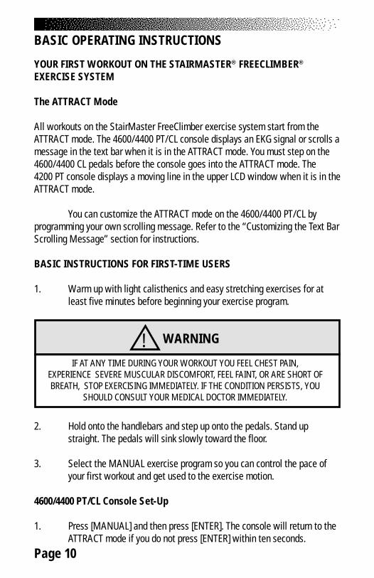
! WARNING
IF AT ANY TIME DURING YOUR WORKOUT YOU FEEL CHEST PAIN,EXPERIENCE SEVERE MUSCULAR DISCOMFORT, FEEL FAINT, OR ARE SHORT OFBREATH, STOP EXERCISING IMMEDIATELY. IF THE CONDITION PERSISTS, YOU
SHOULD CONSULT YOUR MEDICAL DOCTOR IMMEDIATELY.
Page 11
2. The console will prompt you to enter your body weight. Enter yourweight in pounds (or kilograms if the console is set up for metric units).Correct entry errors by pressing [CLEAR] before you press [ENTER].
3. The console will prompt you to enter the workout time in one minuteincrements between five and 60 minutes. Press [1], [0], [ENTER] toexercise for ten minutes. If you do not start exercising within 30seconds, the console will return to the ATTRACT mode.
4200 PT Console Set-Up
1. Look at the upper LCD window. The arrow pointing to the word"Program" should be flashing and "P1" should be displayed.P1 corresponds to the MANUAL program. Press [SELECT].
2. The arrow pointing to the word "Weight" will flash and "150" isdisplayed. Use the [+ or - ARROW] to adjust your body weight. Press[ENTER/SELECT] when it is correct.
3. The arrow pointing to "Speed Level" will flash and "3" is displayed.Press [SELECT].
4. The arrow pointing to the word "Time" will flash and the number "15" isdisplayed. Press [- ARROW] to change the workout time to 10 minutes.Press [SELECT].
Begin Exercising
1. Take deep, comfortable steps. Do not let the pedals touch the floor orcontact the upper stop. When you begin to exercise, the MANUALprogram starts at level three.
2. As you become comfortable with exercise motion, press[+ INCREASE] and [- DECREASE] to adjust your climbing speed.
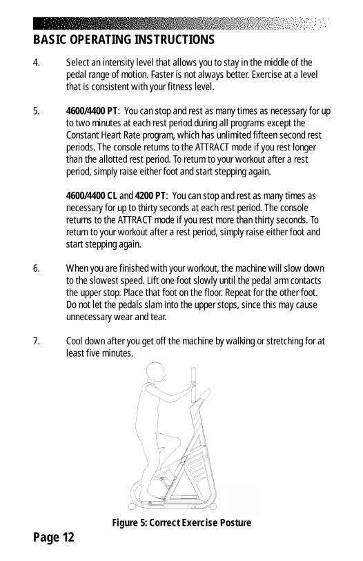
3. Relax and stand up straight while exercising. Use the handlebars forbalance (see Figure 5).
BASIC OPERATING INSTRUCTIONS
Page 12
4. Select an intensity level that allows you to stay in the middle of thepedal range of motion. Faster is not always better. Exercise at a levelthat is consistent with your fitness level.
5. 4600/4400 PT: You can stop and rest as many times as necessary for upto two minutes at each rest period during all programs except theConstant Heart Rate program, which has unlimited fifteen second restperiods. The console returns to the ATTRACT mode if you rest longerthan the allotted rest period. To return to your workout after a restperiod, simply raise either foot and start stepping again.
4600/4400 CL and 4200 PT: You can stop and rest as many times asnecessary for up to thirty seconds at each rest period. The consolereturns to the ATTRACT mode if you rest more than thirty seconds. Toreturn to your workout after a rest period, simply raise either foot andstart stepping again.
6. When you are finished with your workout, the machine will slow downto the slowest speed. Lift one foot slowly until the pedal arm contactsthe upper stop. Place that foot on the floor. Repeat for the other foot.Do not let the pedals slam into the upper stops, since this may causeunnecessary wear and tear.
7. Cool down after you get off the machine by walking or stretching for atleast five minutes.
Figure 5: Correct Exercise Posture
BASIC OPERATING INSTRUCTIONS
Page 13
The StairMaster® FreeClimber® features a digitized contact heart rate monitoringsystem. Through the use of stainless steel sensors built into the upper handlesand sophisticated software, heart rate can be checked at any time during aworkout.
The heart generates a rhythmic, electronic signal each time it beats (theelectrocardiogram or EKG signal). The sensors detect this electrical signalthrough the hands when the sensors are gripped during a workout. The signal isconverted into a heart rate, which is displayed on the console.
The contact heart rate system is very accurate (within 3% of themedical standard), but its ability to detect a heart rate signal is influenced byseveral factors. Movement of the muscles of the upper body produces anelectrical signal that will interfere with the detection of the heart rate signal bythe sensors. Movement of the hands while they are in contact with the sensorsalso produces interference. Calluses and hand lotion act as an insulating layerto reduce the signal strength. Also, the EKG signal generated by some individualsis not strong enough to be detected by the sensors. Typically, these individualsaccount for 5 - 7% of the population. Most people (between 93 – 95%) willnot have a problem with the system provided interference from movement isminimal.
Lightly grip the sensors with each hand. The heart rate display isshown automatically in the upper window the first time the sensors are touched.A valid signal is shown by a pulsating heart icon and the number of beats perminute next to the word “Pulse”. The heart icon will stop beating and twodashes replace the numbers when the sensors are released or an invalid signalis received.
CONTACT HEART RATE (4600 PT/CL)
Page 14
The StairMaster® FreeClimber® 4600/4400 PT/CL features Polar® heart ratemonitoring. The system consists of the receiver, located on the stepper, and atransmitter belt (purchased separately), worn across your chest. The transmitterbelt senses the heart beat and sends a signal to the receiver. Your heart rate, inbeats per minute, is shown on the console text bar.
The transmitter belt attaches an identification number to your heart ratesignal. Once the receiver locks on to your signal, it will ignore all other signalswithout your identification number. Now, two people can exercise side-by-sidewithout interfering with each other's heart rate signal.
Before you put the transmitter belt on, wet the two contact patches (thegrooved rectangles on the reverse side of the belt). Secure the transmitter belt ashigh under the pectoral muscles (chest) as is comfortable. The transmitter beltshould fit snugly and comfortably and allow normal breathing.
When the console detects a heart rate signal, heart rate is shown in thedisplay automatically. The word "PULSE", your heart rate in beats per minute, anda pulsing heart icon are displayed in the text bar.
If you display a statistic other than heart rate during your workout, youcan return to heart rate by pressing the white [0] key. Heart rate is part of theworkout stats scrolling display. Average heart rate is shown at the end of yourworkout. If you wear a transmitter strap during the Fit Test, the average heartrate at the end of each stage is automatically used when estimating maximumaerobic capacity.
POLAR® HEART RATE (4600/4400 PT/CL ONLY)
Page 15
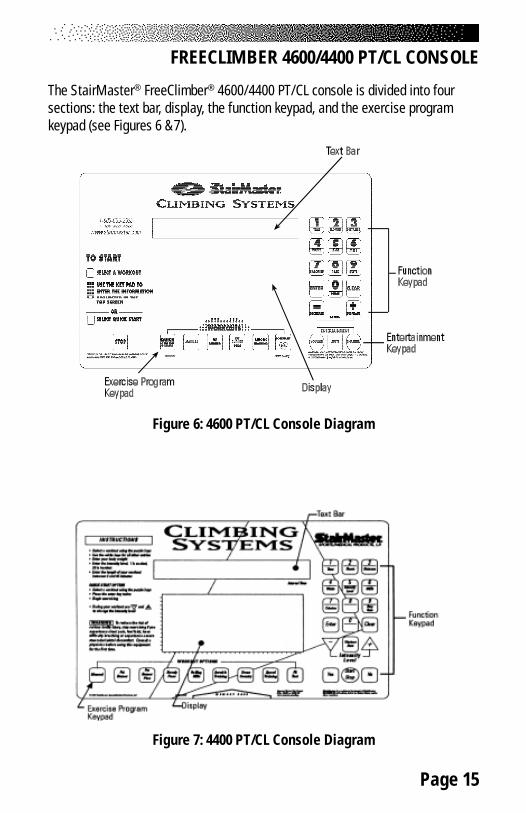
The StairMaster® FreeClimber® 4600/4400 PT/CL console is divided into foursections: the text bar, display, the function keypad, and the exercise programkeypad (see Figures 6 &7).
Figure 6: 4600 PT/CL Console Diagram
Figure 7: 4400 PT/CL Console Diagram
FREECLIMBER 4600/4400 PT/CL CONSOLE
Page 16
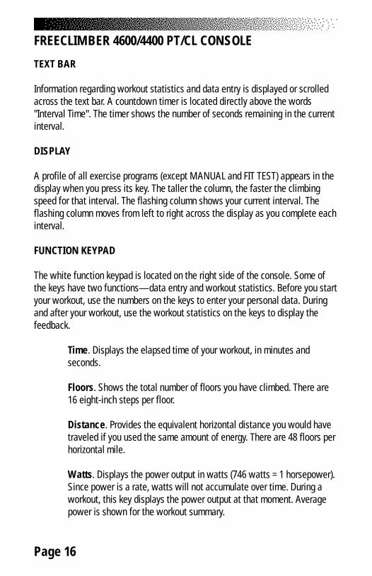
TEXT BAR
Information regarding workout statistics and data entry is displayed or scrolledacross the text bar. A countdown timer is located directly above the words"Interval Time". The timer shows the number of seconds remaining in the currentinterval.
DISPLAY
A profile of all exercise programs (except MANUAL and FIT TEST) appears in thedisplay when you press its key. The taller the column, the faster the climbingspeed for that interval. The flashing column shows your current interval. Theflashing column moves from left to right across the display as you complete eachinterval.
FUNCTION KEYPAD
The white function keypad is located on the right side of the console. Some ofthe keys have two functions—data entry and workout statistics. Before you startyour workout, use the numbers on the keys to enter your personal data. Duringand after your workout, use the workout statistics on the keys to display thefeedback.
Time. Displays the elapsed time of your workout, in minutes andseconds.
Floors. Shows the total number of floors you have climbed. There are16 eight-inch steps per floor.
Distance. Provides the equivalent horizontal distance you would havetraveled if you used the same amount of energy. There are 48 floors perhorizontal mile.
Watts. Displays the power output in watts (746 watts = 1 horsepower).Since power is a rate, watts will not accumulate over time. During aworkout, this key displays the power output at that moment. Averagepower is shown for the workout summary.
FREECLIMBER 4600/4400 PT/CL CONSOLE
Page 17
Intensity Level. Shows the current level between 1 (the easiest) and20 (the hardest). Shows the number of lights in the Manual programbetween 1 and 14.
METs. Gives you the relative energy cost of exercise. MET stands formultiples of the resting metabolic rate. While you are sitting quietly,your body consumes oxygen at the rate of about 3.5 milliliters perkilogram of body mass per minute. When you exercise, your body needsmore oxygen in order to function. For example, exercising at 10 METsrequires ten times the resting rate of oxygen consumption, or about 35milliliters per kilogram per minute. During a workout, this key shows thecurrent MET level. During the workout summary, the average MET levelis displayed.
Calories. Provides a running total of the number of Calories burnedduring a workout.
Step Rate. Indicates the climbing speed in steps per minute. It is basedon an average eight-inch step.
Enter. Confirms workout selections and stores the information used bythe console to calculate workout statistics.
Zero. On 4600/4400 PT/CL models, press this key to see your heart rateduring your workout. Press it during the workout summary to see youraverage heart rate.
Clear. Erases information from the console memory if pressed before[ENTER].
[+ INCREASE] / [- DECREASE]. Increases or decreases theintensity level.
Yes/No (4400 PT/CL). Respond to console prompts.
Start (4400 PT/CL). If pressed while the console is in the ATTRACTmode, the console will display the "Select A Program" prompt.
FREECLIMBER 4600/4400 PT/CL CONSOLE
Page 18
Stop. If pressed at any time, the console will return to the ATTRACTmode.
Workout Stats. If pressed during your workout, all workout statisticscontinuously scroll across the text bar. Press any key to stop scrolling atthat statistic.
If pressed immediately after your workout, the workoutsummary statistics will scroll once across the text bar. Press anykey to stop scrolling at that statistic.
If pressed while the console is in the ATTRACT mode, the finaltotals from the last workout (if the workout was > 10 seconds) willscroll across the text bar. This summary is stored in the consolememory until the next work out is started.
ENTERTAINMENT KEYPAD (4600 PT/CL)
The 4600 PT/CL comes equipped to facilitate the use of commercialentertainment systems.
Volume [+/-]. Increases (+) or decreases (-) the volume level.
Mute. Removes the audio sound from the headphones.
Channel [+/-]. Changes commercial entertainment system channels.
EXERCISE PROGRAM KEYPAD
The purple exercise keypad is located below the display and to the left of thefunction keypad. While the console is in the ATTRACT mode, press one of theexercise program keys to preview the desired workout.
The sequence of prompts for the preset exercise programs is slightlydifferent than the sequence described earlier for the MANUAL program. Afteryou press one of the exercise program keys, the exercise program profile isscrolled across the display.
FREECLIMBER 4600/4400 PT/CL CONSOLE
Page 19
After the profile is scrolled, the prompts are:
• “PRESS ENTER KEY TO ACCEPT”• “ENTER BODY WEIGHT” -- type in your body weight in
pounds (or kilograms if your console is set to metric units).• “ENTER LEVEL 1 - 20” -- select your intensity level with
level 1 being the easiest and level 20 the hardest.• “ENTER TIME 5 - 60” -- select the workout duration in one
minute increments from five to 60.
The Quick Start Option
You can quickly start any workout on the 4600/4400 PT/CL by first pressing oneof the purple exercise program keys* and then pressing [ENTER] twice. On the4600 PT/CL you can also just press the [QUICKSTART] program key to beginexercising. You do not have to enter any other information. The length of theworkout is set automatically and varies with the program. Quick startingMANUAL gives you a 15 minute workout. The preprogrammed workouts last fiveminutes for every thirty intervals. For example, a 60 interval program will last 10minutes. All workout stats displayed at the end of a workout are based on a 175lb. body weight.
*The [CONSTANT HEART RATE] program key on the 4600 PT/CL, and the[FIT TEST] program key on the 4400 PT/CL do not have a quick start option.
The Fit Test
The Fit Test is a program that estimates your maximal aerobic capacity based onyour heart rate response to submaximal exercise. Start the 4600 PT/CL Fit Test bypressing [+ INCREASE], [3], [4], [8], [ENTER] while the console is in the ATTRACTmode. Start the 4400 PT/CL Fit Test by pressing [FIT TEST], [ENTER] while theconsole is in the ATTRACT mode. You will be prompted to enter your age andgender after a short message is scrolled across the display.
Once you have entered the required information, you will step at therate of 43 steps per minute for three minutes. At the end of three minutes, youwill need to enter your heart rate (if you are wearing a heart rate transmitter andusing a 4600 PT/CL, or 4400 CL, your heart rate is entered automatically).
FREECLIMBER 4600/4400 PT/CL CONSOLE
Page 20
○
○
○
○
○
○
○
○
○
○
○
○
○
○
○
○
○
○
○
○
○
○
○
○
○
○
○
○
○
○
○
○
○
○
○
○
○
○
○
○
○
○
○
○
○
○
○
○
○
○
○
○
○
○
○
○
○
○
○
○
○
○
○
○
○
○
○
○
○
○
○
○
○
○
○
○
○
○
○
○
○
○
○
○
○
○
○
○
○
○
○
○
○
○
○
○
○
○
○
○
○
○
○
○
○
○
○
○
○
○
○
○
○
○
○
○
○
○
○
○
○ ○ ○ ○ ○ ○ ○ ○ ○ ○ ○ ○ ○ ○ ○ ○ ○ ○ ○ ○ ○ ○ ○ ○ ○ ○ ○ ○ ○ ○ ○ ○ ○ ○ ○ ○ ○ ○ ○ ○ ○
○ ○ ○ ○ ○ ○ ○ ○ ○ ○ ○ ○ ○ ○ ○ ○ ○ ○ ○ ○ ○ ○ ○ ○ ○ ○ ○ ○ ○ ○ ○ ○ ○ ○ ○ ○ ○ ○ ○ ○ ○
○ ○ ○ ○ ○ ○ ○ ○ ○ ○ ○ ○ ○ ○ ○ ○ ○ ○ ○ ○ ○ ○ ○ ○ ○ ○ ○ ○ ○ ○ ○ ○ ○ ○ ○ ○ ○ ○ ○ ○ ○
○ ○ ○ ○ ○ ○ ○ ○ ○ ○ ○ ○ ○ ○ ○ ○ ○ ○ ○ ○ ○ ○ ○ ○ ○ ○ ○ ○ ○ ○ ○ ○ ○ ○ ○ ○ ○ ○ ○ ○ ○
○ ○ ○ ○ ○ ○ ○ ○ ○ ○ ○ ○ ○ ○ ○ ○ ○ ○ ○ ○ ○ ○ ○ ○ ○ ○ ○ ○ ○ ○ ○ ○ ○ ○ ○ ○ ○ ○ ○ ○ ○
○ ○ ○ ○ ○ ○ ○ ○ ○ ○ ○ ○ ○ ○ ○ ○ ○ ○ ○ ○ ○ ○ ○ ○ ○ ○ ○ ○ ○ ○ ○ ○ ○ ○ ○ ○ ○ ○ ○ ○ ○
○ ○ ○ ○ ○ ○ ○ ○ ○ ○ ○ ○ ○ ○ ○ ○ ○ ○ ○ ○ ○ ○ ○ ○ ○ ○ ○ ○ ○ ○ ○ ○ ○ ○ ○ ○ ○ ○ ○ ○ ○
Note: Keep stepping until the end of the Fit Test.The Fit Test will end if you stop stepping.
The console will prompt you to find your pulse; use the artery belowyour thumb in your wrist or the artery in the side of your neck. Start counting thebeats when the console prompts you—the first beat you feel is zero and thenone and so on. Enter the number of beats you counted in the ten seconds.
You will continue to exercise for three minute bouts of increasing inten-sity until you reach a point where you have entered two heart rate responses be-tween 19 and 25 counts (115-150 beats per minute). The test typically lasts fromnine to 15 minutes.
At the end of the Fit Test, your results scroll across the text bar. Prior toa three minute cool down, your estimated aerobic capacity, expressed in METs, isshown. Next, your results will be compared to normative values for others of yourage and gender. These normative values are based on values developed by theworld renowned exercise physiologist, Dr. Per Olaf Åstrand, and are shown inTable 2. Your results are stored in the console until the next person starts an ex-ercise program. Press [WORKOUT STATS] to review your results.
Table 2. Fitness Rating Norms (METs)
Rating Low Fair Average Above Average SuperiorGender/AgeMen 20-29 <10.8 11.1-12.3 12.6-16.0 16.3-19.7 20.0+ 30-39 <9.7 10.0-11.1 11.4-14.6 14.8-18.3 18.6+ 40-49 <8.6 8.8-10.0 10.3-13.4 13.7-17.1 17.4+ 50-59 <7.1 7.4-8.8 9.1-12.3 12.6-15.7 16.0+ 60-69 <6.0 6.3-7.4 7.7-11.1 11.4-14.0 14.3+Women 20-29 <8.0 8.3-9.7 10.0-13.7 14.0-16.8 17.1+ 30-39 <7.7 8.0-9.4 9.7-13.4 13.7-16.6 16.8+ 40-49 <7.1 7.4-8.8 9.1-12.8 13.1-16.0 16.3+ 50-59 <6.0 6.3-7.7 8.0-11.7 12.0-14.0 14.3+ 60-69 <4.8 5.1-6.3 6.6-10.3 10.6-12.6 12.8+
○ ○ ○ ○ ○ ○ ○ ○ ○ ○ ○ ○ ○ ○ ○ ○ ○ ○ ○ ○ ○ ○ ○ ○ ○ ○ ○ ○ ○ ○ ○ ○ ○ ○ ○ ○ ○ ○ ○ ○ ○
FREECLIMBER 4600/4400 PT/CL CONSOLE
Page 21
FREECLIMBER 4600/4400 PT/CL CONSOLE
Preset Exercise Programs
4600 PT/CL:
There are four preset exercise programs. The exercise speed during the programsvaries automatically over 14 increments within each of the 20 different intensitylevels. Varying the intensity of an exercise program does not change the profileshown on the display. Change the intensity level of your workout by pressing[+ INCREASE] or [- DECREASE]. For each level, the average energy cost of allprograms is about the same.
The FAT BURNER program is a 60 interval workout designed forpeople just starting a weight control program.
The FAT BURNER PLUS program is similar but has 90 intervals. It ismeant for the longer workouts you will need as your fitness levelincreases.
The AEROBIC TRAINING program is a 60 interval workout withslightly more varied speed changes. It is ideal for those long, slowworkouts to increase your aerobic capacity.
The CONSTANT HEART RATE program maintains a chosen targetheart rate by automatically varying the climbing speed during eachworkout. The default target heart rate selected by the console is equalto 70% of your maximum heart rate which is calculated by the followingequation: 220 - (Age) x .70. You may choose a different target heart ratethat is between 100 and 170 beats per minute.
4400 PT/CL:
There are seven preset exercise programs. The exercise speed during theprograms varies automatically over 14 increments within each of the 20 differentintensity levels. Varying the intensity of an exercise program does not changethe profile shown on the display. Change the intensity level of your workout bypressing [+ INCREASE] or [- DECREASE]. For each level, the average energy costof all programs is about the same.
Page 22
The FAT BURNER program is a 60 interval workout designed for peoplejust starting a weight control program.
The FAT BURNER PLUS program is similar but has 90 intervals. It ismeant for the longer workouts you will need as your fitness levelincreases.
The STEADY PACE and ROLLING HILLS programs are 30 intervalworkouts with gradual speed changes. They are geared for those whoare just starting to exercise or for those who need an easy day ofrecovery exercise.
The AEROBIC TRAINING program is a 60 interval workout withslightly more varied speed changes. It is ideal for those long, slowworkouts to increase your aerobic capacity.
The CROSS COUNTRY and SPEED TRAINING programs are 90interval workouts with lots of speed changes to get your legs moving.Think of the terrain you would find on a hike cross country.
THE JACKPOT OPTION
When you finish your workout, a “GOAL ATTAINED” message isnormally displayed in the text bar. This message may be replaced by a NativeAmerican casino style slot machine. When the wheels of the slots stop turning,the console display will spell out either “YOU WIN” or “THE END”. The odds ofwinning may be programmed anywhere from 1-in-1 to 1-in-999. The computerwill then randomly select a winner and display “YOU WIN”, otherwise it willdisplay “THE END.” Workout statistics are shown, as usual, after the jackpotmessage.
Commercial owners often use the jackpot option to further stimulateconsumer interest in their establishment and to add variety to their overallworkout program. Many such owners offer a prize or some tangible incentive forindividuals who win while using the jackpot option. If there is only one prize, youshould remember to disable the option after there is a winner. The jackpot optionremains in effect until disabled by entering zero odds. StairMaster® assumes noliability stemming from the use of the jackpot option. Laws or ordinances in yourarea may govern the use of this option.
FREECLIMBER 4600/4400 PT/CL CONSOLE
Page 23
Turning the Jackpot Option On and Off
1. The computer must be in the ATTRACT mode. Press [INCREASE], [7707],[ENTER].
2. The prompt “ENTER ODDS” will appear in the console display. Enter thenumeric odds you have selected, between 1 and 999.
3. The jackpot results are saved in the console memory until the nextworkout is started. Press [WORKOUT STATS] to review the results.
4. Program the odds to zero to turn the jackpot option off and to return tohaving the “GOAL ATTAINED” message appear after you finish yourworkout.
CUSTOM EXERCISE PROGRAMS
The 4600 PT/CL console has enough memory space for six custom exerciseprograms. The 4400 PT/CL console has enough memory space for nine customexercise programs. Only the exercise profile is saved. You must enter your bodyweight, the intensity level, and the workout time when you use the customprogram. Custom programs have a quick start option, but the time is limited tofive minutes.
Programming Your Workout
1. The console must be in the ATTRACT mode. Press [+ INCREASE],[1], [6], [5], [0], [ENTER]. Press the exercise program keypadbutton that you want to assign to your custom program.
2. If you select an exercise program keypad button that is alreadyprogrammed, the profile will appear; it can be modified orcompletely rewritten. If the exercise program keypad button wasnot previously programmed, you will see a single row of dotsalong the bottom of the display.
3. The flashing dot or column indicates which interval can be modified.Press the [+ INCREASE] or [- DECREASE] to make the column
FREECLIMBER 4600/4400 PT/CL CONSOLE
Page 24
taller or shorter. Press [ENTER] to move one column to the rightand [CLEAR] to move one column to the left.
4. When all of the intervals are correctly programmed, press[0- 4600 PT/CL] or [YES - 4400 PT/CL] to save the profile. Press[STOP - 4600 PT/CL] or [START/STOP - 4400 PT/CL] to abort theprogramming process without saving the profile.
Using a Custom Program
1. Press [- DECREASE] and the exercise program keypad button youassigned to the custom program.
2. Enter your body weight, the intensity level and the workout timein response to the prompts.
CUSTOM SCROLLING MESSAGE
The message that scrolls across the text bar during the ATTRACT mode can bereplaced with a message of your choice. The console accepts messages up to128 characters in length, including spaces. To program your message:
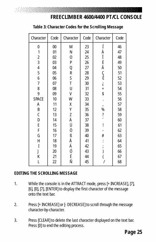
1. Encode your message using the character codes listed in Table 3.
2. While the console is in the ATTRACT mode, press [+ INCREASE], [7],[6], [0], [7], [ENTER].
3. Enter the two-digit code for each letter of your message. Theletter will appear in the text bar as you press the second digit ofeach code. Do not press [ENTER] between the code numbers.
4. For example, to program the message “EXERCISE IS FUN”, press[+ ARROW], [7], [6], [0], [7], [ENTER]. Then press [1], [5], [3], [4], [1], [5],[2], [8], [1], [3], [1], [9], [2], [9], [1], [5], [1], [0], [1], [9], [2], [9], [1], [0], [1],[6], [3], [1], [2], [4], [ENTER]. At that point, your message will beginscrolling. The console is again in the ATTRACT mode.
5. If you make a mistake while entering the codes, press [CLEAR] toerase the last character entered.
FREECLIMBER 4600/4400 PT/CL CONSOLE
Page 25
Table 3: Character Codes for the Scrolling Message
EDITING THE SCROLLING MESSAGE
1. While the console is in the ATTRACT mode, press [+ INCREASE], [7],[6], [0], [7], [ENTER] to display the first character of the messageonto the text bar.
2. Press [+ INCREASE] or [- DECREASE] to scroll through the messagecharacter-by-character.
3. Press [CLEAR] to delete the last character displayed on the text bar.Press [0] to end the editing process.
FREECLIMBER 4600/4400 PT/CL CONSOLE
retcarahC edoC retcarahC edoC retcarahC edoC
0123456789
ECAPSABCDEFGHIJKL
0010203040506070809001112131415161718191021222
MNOPQRSTUVWXYZÄÜÖßÅÁÓÉÑ
3242526272829203132333435363738393041424344454
ÍÀÎÈÂÇÊ¿+$.,
%?´!-#:;)(/
6474849405152535455565758595061626364656667686
Page 26
4. To edit multiple characters at one time, press [9], [9], [ENTER] to eraseall of the characters to the right of the last character displayed on thetext bar.
5. To erase the entire message, press [+ INCREASE], [1], [0], [5], [ENTER]while in the ATTRACT mode.
6. The edited message will scroll across the text bar. If you have erasedthe entire message, the text bar area will be blank during the ATTRACTmode.
7. Press [+ INCREASE], [2], [1], [2], [3], [ENTER] to display the defaultscrolling message on the text bar.
8. Press [+ INCREASE], [2], [1], [2], [1], [ENTER] to display your customscrolling message on the text bar.
CHANGING THE CONSOLE UNITS AND PROMPT LANGUAGE
The console is set at the manufacturing facility to English language promptsand English units. While the console is in the ATTRACT mode, you can set theconsole for foreign language prompts or metric units.
1. To change the prompt language, press [+ INCREASE], [7], [4], [2], [4],[ENTER]. Press the code number for the desired language (see Table 4)and then press [ENTER].
2. To change the console to metric units, press [+ INCREASE], [9], [7], [6],[0], [ENTER] and then [1]. Press [+ ARROW], [9], [7], [6], [0], [ENTER] andthe [0] to change back to English units.
CONSOLE CODES
The console codes and the corresponding functions are listed in Table 4. Withoutstanding on the pedals, press [+ INCREASE] before pressing the code's numberkeys, and then press [ENTER]. Some codes, like the one to change the languageof the console prompts, have options that require you to press a second codenumber and then [ENTER] to select that option.
FREECLIMBER 4600/4400 PT/CL CONSOLE
Page 27
Table 4. Console Codes
FREECLIMBER 4600/4400 PT/CL CONSOLE
edoC noitcnuF
501 egassemgnillorcsdemmargorpmotsucehtsraelC
70101234
edomcitsongaiDehtsetavitcAtsetyalpsiDtsetrekaepS
tsetdapyeKtsetdeepS
tsetnoisivererawtfoS
801 tseterawtfosetartraeH
0561 tuokrowmotsucasmargorP
1212 egassemgnillorcsmotsucehtnosnruT
3212 egassemgnillorcsmotsucehtffosnruT
4247 stpmorpelosnocehtfoegaugnalehtsegnahC
706799
noitpoegassemmotsucehtnosnruTnoitcnufgnitideegassemgnillorcsrabtxeT
3077 noitamrofniegasuenihcamsyalpsiD
407701
fforonorekaepselosnocehtnrutotuoyswollAnorekaepsehtsnruTfforekaepsehtsnruT
507701
fforonoerutaefetaRtraeHehtnrutotuoyswollAnoerutaefetaRtraeHehtsnruTffoerutaefetaRtraeHehtsnruT
067901
elosnocehtybdeyalpsidstinuehtegnahcotuoyswollAstinuhsilgnEotelosnocehtsegnahC
stinucirtemotelosnocehtsegnahC
667901
noisreverawtfosehtegnahcotuoyswollAerawtfosTP0044otsegnahCerawtfosTP0007otsegnahC
50479 emittuokrowmumixamehtsegnahC
57425 setunim06ottimilemitteseR
Page 28
The StairMaster® FreeClimber® 4200 PT console is divided into two LCD displaywindows. There is a four-function keypad located below the bottom window (seeFigure 8). While you are exercising, the bottom window scrolls through a displayof four workout statistics. An arrow on the side of each LCD window points tothe name of what is being displayed.
Figure 8: 4200 PT Console Diagram
TOP WINDOW
The top LCD window displays information while you set up your workout. It alsodisplays elapsed time during your workout or during your rest period.
Workout Setup
1. While the console is in the ATTRACT mode, either press [START/STOP]or step on the pedals. Look at the top LCD window.
FREECLIMBER 4200 PT CONSOLE
Page 29
2. The arrow pointing to the word "Program" should be flashing and "P1"should be displayed. P1 corresponds to the MANUAL program. Use the[+ or - ARROW] to change the workout option. "P2" corresponds toSteady Pace, "P3" to Fat Burner, and "P4" to Aerobic Training. Thedifferent workout option profiles are shown on the right side of theconsole.
3. When the correct workout option is displayed on the top LCD window,press [ENTER/SELECT].
4. The arrow pointing to the word "Weight" will flash and the number"150" will be displayed. Use [+ or - ARROW] to adjust it to your bodyweight. Press [ENTER/SELECT] when it is correct.
5. If you selected a workout option other than "P1" (MANUAL), the arrowpointing to the words "Speed Level" will flash and the number "10" willbe displayed. Adjust the level between 1 (the slowest) and 20 (thefastest) with [+ or - ARROW]. Press [ENTER/SELECT] when it is correct
If you selected MANUAL, your workout will start at speedlevel 3. Level 1 is the slowest and level 20 is the fastest.Use the [+ or - ARROW] to adjust the climbing speed once yourworkout begins.
6. The arrow pointing to the word "Time" will flash and the number "15"will be displayed. Press [+ or - ARROW] to adjust the length of yourworkout between 5 and 45 minutes.
7. Press [ENTER/SELECT]. Begin exercising.
FREECLIMBER 4200 PT CONSOLE
Page 30
Timer
During your workout, the top window keeps track of your workout time in min-utes and seconds. The display arrow points to the word "Time" on the console.
You may rest for up to 30 seconds at any time during your workout.Either stop stepping or press [START/STOP] to begin your rest period. To resumeyour workout, step on the pedals. If you press [START/STOP] during a rest period,or if you rest for more than 30 seconds, the console will return to the ATTRACTmode.
BOTTOM WINDOW
The bottom LCD window keeps track of four different statistics during your work-out: the number of Calories burned, the climbing speed in steps per minute, thetotal number of floors climbed, and the total distance covered. As the consolescrolls through each statistic, an arrow on the side of the display window pointsto the name of what is being shown.
Calories. Provides a running total of the number of Calories burnedduring a workout.
Steps/Min. Indicates the climbing speed based on an eight-inch step.
Floors. Shows the total number of floors you have climbed. There are16 eight-inch steps per floor.
Distance. Provides the equivalent horizontal distance you would havetraveled if you used the same amount of energy. There are 48 floors perhorizontal mile.
When the display arrow points to the word "Scan", all workoutstatistics are scrolled. Press [ENTER/SELECT] during your workout to lock thebottom display window on any one statistic. For instance, press [ENTER/SELECT]three times to lock the display on the total number of floors climbed. Press[ENTER/SELECT] two more times to resume scrolling the statistics. During restperiods, only Calories, Floors, and Distance are shown (even if the display waslocked on one statistic). At the end of your workout, these same three statisticsare shown one last time.
FREECLIMBER 4200 PT CONSOLE
Page 31
Keypad
ENTER/SELECT. During workout setup, press this key to enter yourpersonal information and then move to the next entry. During yourworkout, press this key to lock the bottom display window on any onestatistic or to return to the scrolling mode.
+ or - ARROWS. During workout setup, press these keys to adjust yourpersonal information before you press [ENTER/SELECT]. During yourworkout, use these keys to adjust the level (or climbing speed).
START/STOP. Press this key while the console is in the ATTRACT modeto begin the workout setup. If pressed at any time during workout setup,all entries are cleared and workout setup starts over again. If pressedduring a workout, a 30 second rest period is started. If pressed during arest period, the console returns to the ATTRACT mode.
QUICK START OPTION
You can quickly start the MANUAL program ("P1") by pressing[ENTER/SELECT] twice (double-clicking) at the start of workout setup.The workout statisics are based on a 150 pound person, the climbing speedstarts at level 3, and the workout time is set to 15 minutes. Use the[+ or - ARROW] to adjust the climbing speed once your workout starts.
FREECLIMBER 4200 PT CONSOLE
Page 32
MAINTENANCE INSTRUCTIONS
HELPFUL HINTS
Read all maintenance instructions thoroughly before beginning work. In somecases, an assistant is required to perform the necessary tasks.
All references to the right or left side and to the front or back aremade as if you were on the machine ready to exercise. For example, the consoleis located on the front of the machine. Major component names and locationsare shown in Figure 10. When ordering parts, reference the part number inparentheses next to the part's description on the figures.
TOOL LIST
The following tools are needed to perform service and maintenance:
• standard screwdriver • phillips screwdriver• combination wrenches (sizes 7/16 - 3/4") • adjustable wrench• combination pliers • locking pliers• volt-ohm meter (multimeter) • wire stripper/crimper tool• allen wrench set (sizes 5/64 - 1/4") • external snap ring pliers• shop goggles or other eye protection • torque wrench• socket set or nut driver set (sizes 1/4 - 3/4" in 1/16" increments)
MAINTENANCE RECORDS
The 4600/4400 PT/CL console will keep track of the following data onmachine usage:
• The number of hours the power supply was turned on.• The number of hours the machine was in use.• The total number of floors climbed.• The number of exercise programs started.• The hours of MANUAL use.
To display the data, press [+ INCREASE], [7], [7], [0], [3], [ENTER] whilethe console is in the ATTRACT mode. The console will display the data in thesequence listed above. The machine may show a few hours of use due to testingat the manufacturing facility.
Page 33
The 4200 PT console keeps track of the number of hours the machinewas used and the total number of floors climbed. From the ATTRACT mode, press[+ ARROW] and then double-click [RESET]. The hours are shown in the top LCDwindow and the total floors are shown in the bottom LCD window.
INITIAL SERVICE
Upon receiving your machine, use a soft, clean towel to wipe off the dust whichmay have accumulated during shipping. Your new machine will require minorassembly. Refer to the “Installation Instructions” section for details.
PREVENTIVE MAINTENANCE
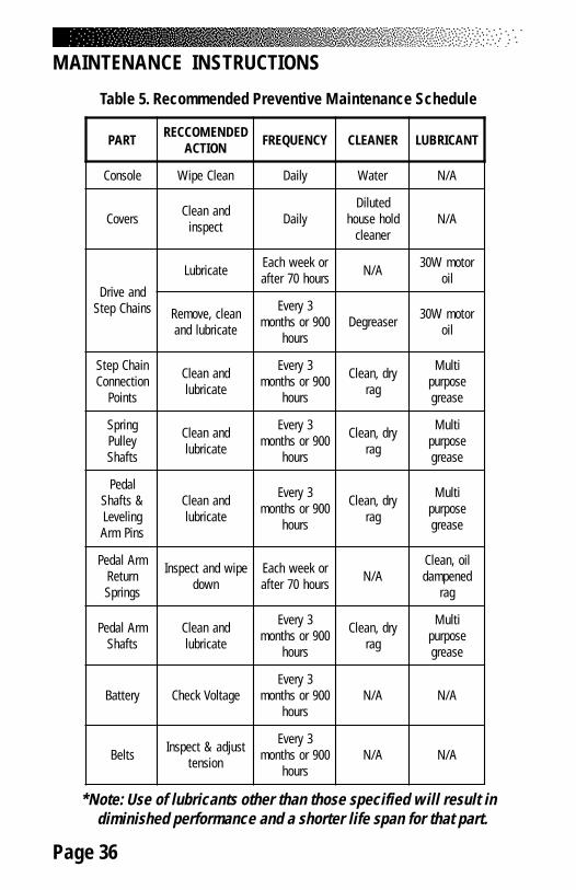
Most of these preventive maintenance procedures can be performed afterremoving the mid cover. The preventive maintenance schedule is summarized inTable 5. The schedule is based on normal usage in a commercial health clubenvironment; adjust the schedule to meet actual machine usage. Refer to the“Parts Removal and Replacement” section for all disassembly and assemblyinstructions.
Cleaning
1. DO NOT USE GLASS CLEANERS OR ANY OTHER HOUSEHOLD CLEANERON THE CONSOLE. Clean the console daily with a water-dampenedcloth and wipe dry after cleaning.
2. Clean the exterior of the machine daily using soap and water or adiluted household cleaner such as Fantastic®.
3. Thoroughly clean the entire machine, including the interior, at least oncea week (see Table 5).
Inspecting
1. Inspect the frame for any rust, bubbling, or paint chips during theweekly cleaning. The salt in perspiration can damage the unpaintedsurfaces.
MAINTENANCE INSTRUCTIONS
Page 34
2. Inspect the Poly-V belt and HTD belts for excessive wear during thequarterly lubrication. Adjust the belt tension if necessary.
LUBRICATION
There are nine components that need periodic lubrication: the drive chain, thestep chains, the pedal arm return springs, the step chain connection points, thepedal arm bushings, the leveling arm bushings, the spring pulley shafts, thepedal shafts and the leveling arm pins. These parts are shown in Figure 10.Remove the bottom cover to get to the components.
1. Place a protective mat on the floor while you lubricate your machine. Arubber floor mat is available from StairMaster® Sports/MedicalProducts, Inc.
2. Lubricate the drive chain and the step chains weekly. Try to penetratethe entire length of the chains with 30W motor oil.
3. Remove the drive chain and step chains every three months tothoroughly clean and lubricate them. Use a mild degreaser and a stiffbrush to remove dirt and corrosion from the chains.
4. Unhook the pedal arm return springs from the spring hanger everyweek. To protect them from corrosion, wipe the entire length of eachpedal arm return spring with a cloth dampened with 30W motor oilbefore reconnecting it. Replace the spring if it is rusty or otherwisedamaged.
5. Remove the double pitch master link from the step chain connectionpoints every three months. Clean the master link and the bushing in thepedal arm. Lubricate the master link and bushing with a thin coat ofmulti-purpose grease before reassembling.
6. Remove the pedal arms and leveling arms every three months. Clean thepedal arm and leveling arm shafts and bushings with a clean cloth.Protect the shafts from corrosion by wiping them with a cloth dampenedwith 30W motor oil.
7. Remove the spring pulleys every three months. Clean the spring pulley
MAINTENANCE INSTRUCTIONS
Page 35
shafts with a dry cloth. Protect the shafts from corrosion with a thincoat of multi-purpose grease before reassembling.
8. Remove the pedals every three months. Clean the pedal shaft andleveling arm pin with a dry cloth. Protect the pedal shaft and levelingarm pin from corrosion with a light coat of multi-purpose grease beforereassembling.
Battery Charge
If you have a 4600/4400 CL, remove the bottom cover and check the batteryvoltage level every three months.
1. Using your multimeter, touch the red lead to the positiveterminal of the battery and the black lead to the negative terminal.
2. If the voltage level is less than 6.1 VDC, charge the battery. Plugthe wall pack battery charger into the connector located near thebottom of the left bottom cover. Charge the battery for approximately24 - 48 hours and then recheck it. It is okay to use machine while thebattery charger is connected.
Battery Disposal
When ordering new batteries, you will need to properly dispose of (recycle) yourold lead-acid batteries. Most federal and state regulations require lead-acidbatteries be recycled.
Do not throw away old batteries. Lead is a toxic heavy metal hazardousto living organisms. Disposal instructions and a list of recycling centers aretabulated in the Appendix. If you have questions, contact the Customer ServiceDepartment at (800) 331-3578.
MAINTENANCE INSTRUCTIONS
! WARNING
TO REDUCE THE POSSIBILITY OF SLIPPING, BE SURE THE PEDALAREA IS FREE OF GREASE OR OIL. WIPE ANY EXCESS OIL OFF
THE MACHINE SURFACES.
Page 36
MAINTENANCE INSTRUCTIONS
Table 5. Recommended Preventive Maintenance Schedule
*Note: Use of lubricants other than those specified will result in diminished performance and a shorter life span for that part.
TRAP DEDNEMOCCERNOITCA YCNEUQERF RENAELC TNACIRBUL
elosnoC naelCepiW yliaD retaW A/N
srevoC dnanaelCtcepsni yliaD
detuliDdlohesuoh
renaelcA/N
dnaevirDsniahCpetS
etacirbuL rokeewhcaEsruoh07retfa A/N rotomW03
lio
naelc,evomeRetacirbuldna
3yrevE009roshtnom
sruohresaergeD rotomW03
lio
niahCpetSnoitcennoC
stnioP
dnanaelCetacirbul
3yrevE009roshtnom
sruoh
yrd,naelCgar
itluMesoprup
esaerg
gnirpSyelluPstfahS
dnanaelCetacirbul
3yrevE009roshtnom
sruoh
yrd,naelCgar
itluMesoprup
esaerg
ladeP&stfahSgnileveLsniPmrA
dnanaelCetacirbul
3yrevE009roshtnom
sruoh
yrd,naelCgar
itluMesoprup
esaerg
mrAladePnruteRsgnirpS
epiwdnatcepsnInwod
rokeewhcaEsruoh07retfa A/N
lio,naelCdenepmad
gar
mrAladePstfahS
dnanaelCetacirbul
3yrevE009roshtnom
sruoh
yrd,naelCgar
itluMesoprup
esaerg
yrettaB egatloVkcehC3yrevE
009roshtnomsruoh
A/N A/N
stleB tsujda&tcepsnInoisnet
3yrevE009roshtnom
sruohA/N A/N
Page 37
GENERAL TROUBLESHOOTING GUIDELINES
This troubleshooting section is organized into three basic problem sections:electrical troubleshooting, console diagnostics, and mechanical troubleshooting.Once you have identified the problem section, perform all the tests in the sameorder as written. To order a replacement part or for help with troubleshooting,contact our Customer Service Department. Refer to the Appendix for theappropriate phone number.
ELECTRICAL TROUBLESHOOTING
The 4600/4400 PT electrical system has three major components: the power sup-ply, the power cables and the console. The 4600/4400 CL also has three majorcomponents: the battery, the power cables, and the console. The console, powersupply and battery are not serviceable by the owner. If any of these parts are in-operable, they must be replaced. Opening the console or the power supply willvoid the warranty.
4600/4400 PT:
1. Use a voltmeter set on VAC to verify that the AC wall outlet has 100to 120 VAC (or 220 to 240 VAC, if applicable). If you do not have avoltmeter plug in an alternate AC-powered device (a lamp, for example).If the device does not work when plugged into the AC wall outlet,consult an electrician for further assistance and then retest the AC walloutlet.
2. Plug the power supply into the wall outlet. The green Light EmittingDiode (LED) on the power supply should be on. If the LED does not lightup, replace the power supply.
3. Disconnect the DC cable from the left side panel. Set the voltmeter toVDC and test for 12 - 19 VDC in pins #1 (+) and #2 (-). Replace thepower supply if the voltage reading is outside the specified range.
4. Remove the bottom cover and connect the DC cable to the powerconnector on the left side of the frame. Locate the black and whitewires on the backside of the power connector.
TROUBLESHOOTING
Page 38
5. Follow the white power connector wire to the where it plugs into themain cable white wire, and disconnect it from the main cablewhite wire.
6. Set your voltmeter to VDC. Connect the positive lead of yourvoltmeter to the white wire from the power connector and touch thegray casing of the alternator with the negative lead of your voltmeter.
7. DC voltage measured should be 12 - 19 VDC. Replace the powerconnector if the voltage is not the same value as in step 3. Connectthe two white wires.
8. Remove the console knobs from the back of the console, lift the consoleup, and disconnect the main cable from the console.
9. Test for 12 - 19 VDC in pins #1 (+) and #9 (-) in the main cableconnector. Replace the main cable if the voltage reading is notthe same as in step 7.
10. If all voltage readings have been within the specified range and theconsole will not power up, the console should be replaced.
Alternator Test
11. Check for loose wiring connections on the alternator, diode and loadresistor (see Final Assembly Figure).
12. Perform the Positive Output to Field test on the alternator:
• Turn the power off• Remove the black wire from the B+ terminal on the alternator• Remove the brown wire from the field terminal on the alternator• Place a short wire with alligator clips on the B+ terminal and the
field (FLD) terminal of the alternator• Step on the machine for approximately 10 - 15 seconds• If full resistance is achieved during this time, your alternator
has correct current flow. If no resistance is achieved, replacethe alternator.
ELECTRICAL TROUBLESHOOTING
Page 39
Diode Test
13. Remove the brown wire and diode from the field terminal of thealternator and set your voltmeter to the Ohms setting.
14. Place one lead from the voltmeter on each end of the diode, and thenreverse the leads. A diode that is good will show a high reading in onedirection and a low reading when the leads are reversed. Replace thediode if the readings recorded are both high or both low.
Resistor Test
15. Remove one wire from the load resistor (see Final Assembly Figure)and place one lead from the voltmeter on each of the threaded posts onthe load resistor. Replace the load resistor if the voltmeter does notread 0.5 Ohms (± 10%).
4600/4400 CL:
Battery Test
1. Remove the mid cover and top covers and unplug the battery from thepower control board. Locate pins #1 & 2 in the end of the cable. Use avoltmeter to verify that the voltage is a minimum of 6.1 VDC. Reconnectthe battery back to the power control board and install the batterycharger for at least 24 hours if the voltage measured is below 6.1 VDC.
2. Remove the console knobs from the back of the console, lift the consoleup, and disconnect the main cable from the console.
3. Step up on the machine. With the voltmeter set to DC voltage, testfor greater than 6.1 VDC in pins #1 (-) and #8 (+) in the main cableconnector while stepping. Replace the main cable if the voltage readingis less than 6.1 VDC. Next, Check for continuity in the main cable (seeFinal Assembly Figure).
4. If all voltage readings have been within the specified range and theconsole will not power up, the console should be replaced.
ELECTRICAL TROUBLESHOOTING
Page 40
Alternator Test
5. Perform the Positive Output to Field test on the alternator:
• Unplug the battery from the power control board• Remove the black wire from the B+ terminal on the alternator• Remove the brown wire from the field terminal on the alternator• Place a short wire with alligator clips on the B+ terminal and the
field (FLD) terminal of the alternator• Step on the machine for approximately 10 to 15 seconds• If full resistance is achieved during this time, your alternator
has correct current flow. If no resistance is achieved, replacethe alternator.
Resistor Test
6. Unplug the load resistor from the power control board and set yourvoltmeter to Ohms. Place one lead from the voltmeter on each of thethreaded posts on the load resistor. Replace the load resistor if thevoltmeter does not read 2.5 Ohms (± 10%).
7. If the problem still exists, contact the Customer Service Department at800-331-3578.
ELECTRICAL TROUBLESHOOTING
Page 41
The following tests are performed while the console is in the DIAGNOSTIC mode.While the console is in the ATTRACT mode, and without stepping on the pedals,press [+INCREASE], [1], [0], [7], [ENTER] to activate the DIAGNOSTIC mode. Thenumbers will not appear on the display as you enter them. If the console fails anytest, the console should be replaced or exchanged. To return to the ATTRACTmode, press either [CLEAR] or [START/STOP] while in the DIAGNOSTIC mode.
Display Test
Use this test if the console display or text bar exhibits blank spots during use.This test checks for inoperable Light Emitting Diodes (LEDs) in the console dis-play and the text bar. If any LED will not light, replace the console.
1. From the DIAGNOSTIC mode, press [0] to start the test.
2. All LEDs in the console display will flash on and off as a block.
3. Press [CLEAR] to end the test.
Speaker Test
Use this test to make sure the console speaker is fully operational. The speakerwill ascend and then descend through the musical scale.
1. From the DIAGNOSTIC mode, press [1] to start the test.
2. Press [ENTER] to pause the test. Press [CLEAR] to end the test.
Keypad Test
Perform this test if you are having trouble entering data into the console. If youcannot enter the DIAGNOSTIC code due to an inoperable keypad, replace theconsole.
1. From the DIAGNOSTIC mode, press [2] to start the test.
2. The display LEDs will light up in an L-shaped formation, representingthe keypad matrix. Pressing a button on either the exercise program
4600/4400 PT/CL CONSOLE DIAGNOSTIC TESTS
Page 42
keypad or the function keypad will light an LED within the outline on thedisplay that corresponds to that button's position on the console.
3. Firmly press each button. If the LED corresponding to the buttonyou pushed does not light up, the keypad is bad and the console shouldbe replaced.
4. Press [CLEAR] to test the LED and then end the test 10 seconds later.
Speed Test
Use this test to verify the electronic speed control routines of the console. Youwill need to briefly exercise on the machine for this test.
1. From the DIAGNOSTIC mode, press [3] to start the test.
2. The console will be set at a certain speed. The alternator speed, inRPMs, is displayed on the text bar as “Target” and a single column oflights will light up on the left side of the display.
3. Begin exercising. As you move the pedal arms, the text bar willalternately show the actual RPM and the target RPM.
4. Press [CLEAR] to return to the DIAGNOSTIC mode.
Software Revision Level Test
This test allows you to check the version number of the software installed in theconsole.
1. From the DIAGNOSTIC mode, press [4] to start the test.
2. The software version number will be scrolled across the text bar.The console automatically returns to the DIAGNOSTIC mode.
4600/4400 PT/CL CONSOLE DIAGNOSTIC TESTS
Page 43
4600/4400 PT/CL CONSOLE DIAGNOSTIC TESTS
Contact Heart Rate Test (4600/4400 PT/CL only)
The contact heart rate system is made up of the console and the contact heartrate handles. You can test each component by performing the following steps:
1. While the console is in the ATTRACT mode (noted by a simulated EKGsignal in the console display), or at the “SELECT A WORKOUT” prompt,press [+INCREASE], [1], [0], [8], [ENTER].
2. After approximately ten seconds a flashing ♥ should be displayed inthe console text bar. Your heart rate, in beats per minute, will show nextto the heart icon. If the heart icon does not show, or if your heart rate isnot displayed in the text bar, you have a problem with either theconsole or the contact heart rate handles.
3. If possible, replace or exchange your console with a console (fromthe same type of machine) you know is working and retest themachine.
4. If possible, replace or exchange your contact heart rate handles withhandles (from the same type of machine) that you know is working andretest the machine.
5. If you do not have spare parts contact the Customer Service Departmentat 800-331-3578.
Polar® Heart Rate Test (4600/4400 PT/CL only)
The Polar heart rate system is made up of the console, the heart rate receiver,and the chest strap (available separately). You can test each component byperforming the following steps:
1. You will need to put a chest strap on in order to test the Polar heartrate. Before you put the chest strap on, wet the two contact patches.Secure the chest strap as high under your pectoral muscles (chest) asis comfortable. The chest strap should fit snugly, comfortably, andallow normal breathing.
Page 44
2. While the console is in the ATTRACT mode (noted by a simulated EKGsignal in the console display), or at the “SELECT A WORKOUT” prompt,press [+INCREASE], [1], [0], [8], [ENTER].
3. A flashing ♥ should be displayed in the console text bar. Your heartrate, in beats per minute, will show next to the heart icon. If the hearticon does not show, or if your heart rate is not displayed in the text barthen you have a problem with either the console, chest strap, or heartrate receiver.
4. Test your chest strap with a machine that you know is working, or witha heart rate watch that you know is working.
5. If possible, replace or exchange your console with a console (fromthe same type of machine) that you know is working and retest themachine.
6. Visually check that the heart rate receiver is positioned correctly in theneck cover. The heart rate receiver jack should point down. Ensure thatthe heart rate receiver is connected to the console, and that theconnection is not loose. If possible, swap the heart rate receiver withone from another machine.
7. If the problem still exists, contact the Customer Service Department at800-331-3578.
4600/4400 PT/CL CONSOLE DIAGNOSTIC TESTS
Page 45
If you hear a grinding or clicking noise, or experience excessive vibration duringexercise, or if the pedals are not functioning properly, you probably have a prob-lem in the drive train. Attempt to isolate the problem area by performing the fol-lowing tests in precisely the order listed below. Refer to the “Parts Removal andReplacement” section for all disassembly and assembly instructions.
1. Unplug the machine and remove the bottom side covers.
2. Noise can be generated by a Poly-V or HTD belt that is either too tightor too loose. Check the condition and the tension of the belts. Replaceworn belts. Adjust the belt tension according to the instructions in the"Parts Removal and Replacement" section.
3. Remove the Poly-V belt and move the pedal arms. If the noise no longerexists, check the condition of the alternator. If the noise is still present,go to step #4.
• Disconnect the DC power cable if you have a 4600/4400/4200 PT orunplug the connector from position J4 on the power supply circuitboard if you have a 4600/4400 CL. Spin the alternator pulley withyour fingers. It should spin freely and remain spinning for at leasttwo revolutions. If it does not, the alternator should be replaced.
• If the alternator does spin freely, check the alternator for noise,roughness, or the presence of an excessive amount of black powderinside the alternator or near the outside of the case. If any of theseconditions exist, the brushes might be bad and the alternatorshould be replaced.
• Do not reinstall the Poly-V belt if performing step #4. Plug in theconnector at position J4 or reconnect the DC power cable,as applicable.
MECHANICAL TROUBLESHOOTING
TO REDUCE THE RISK OF INJURY, DO NOT OPERATE THE MACHINEWHILE THE COVERS ARE REMOVED. DO NOT DEPRESS OR RAISE THE PEDALS WHILE
ANYONE'S HANDS ARE INSIDE THE MACHINE.
! WARNING
Page 46
4. Remove the drive and step chains. Check the condition of the chains byflexing each link up and down. Each link should move freely. Replacethe chain if any stiff or inflexible links are found or if the chain is rusty,corroded or otherwise damaged. Do not reinstall the chains.
5. Remove the pedals. Clean any corrosion off the pedal shaft with an oil-dampened rag. Apply a thin coat of multi-purpose grease to the shaft. Ifthe noise persists, go to step 6.
6. Check the step chain connection point. Clean and grease the master linkand bushing. Replace damaged parts.
7. Check the drive hub assembly.
• Check the condition of the drive sprocket teeth. The teeth shouldnot be unevenly worn. Replace the worn sprocket(s).
• The drive sprockets work independently of one another. Eachsprocket should turn freely in one direction and lock when turned inthe other direction. Replace an inoperable drive sprocket.
• Remove the drive shaft. Inspect the bearings in the drive hub.Replace the drive hub assembly if the shaft does not spin freely orif there is excessive radial play at the shaft. Be careful not to getdirt into the hub.
• Inspect the ends of the drive shaft (at the sprocket attachmentpoints) for signs of wear or scoring. Replace the shaft if it isexcessively worn.
8. Check the pedal arm and leveling arm shafts by removing both the rightand left pedal and leveling arms. Inspect the shafts and the bushings forsigns of wear and corrosion. Replace the bushing(s) if worn.
• Clean all corrosion off the pedal arm shaft and leveling arm shaftand bushings. Wipe the shafts with an oil-dampened cloth beforereassembling. DO NOT SAND THE PEDAL ARM SHAFT ORLEVELING ARM SHAFT.
MECHANICAL TROUBLESHOOTING
Page 47
9. Remove the HTD belt. Inspect the belt, the Poly-V pulley and the HTDpulley for excessive wear. Replace if necessary. The Poly-V pulleyshould spin freely. If it does not, replace the eccentric shaft assembly.
10. Inspect the HTD pulley for excessive wear and smoothness ofoperation. If the pulley is worn, replace it. If it does not spin freely,remove the first reduction shaft and inspect the bearings.
11. Reinstall all parts, ensuring the proper tension of the Poly-V and HTDbelts and the drive chain (see Figure 30). Clean and lubricate the driveand step chains with 30W motor oil before reinstalling them.
MECHANICAL TROUBLESHOOTING
Page 48
COVERS
There are three covers on the 4400 PT/CL and the 4200 PT: the top cover, the midcover and the bottom cover. The top and bottom covers are made of a right andleft section. Do not separate the right and left sections of either the top orbottom covers to perform most maintenance tasks. Access to the interior of themachine takes three steps: remove the mid cover; slide the top cover upward;and remove the bottom cover (see Figure 27).
The 4600 PT/CL has an additional shield over the handles.Access to the interior of the machine takes four steps: remove the mid cover;remove the shield; separate the top covers and remove the bottom cover.
Mid Cover
1. Use the fastener removal tool to remove each of the four fastenerpins on the mid cover (see Figure 28).
2. Stand on the pedals and keep them on the floor.
3. Slide the mid cover down and away from the machine. Removethe cover from the frame tube. Carefully let both pedals return tothe upper stops.
Top Cover
1. 4400 PT/CL, 4200PT: Remove the mid cover and the console.
4. Release the pins along the middle seam of the top cover. Use asmall phillips screwdriver or similar tool to push the fastener center pinin at least halfway. Use your fingers to remove the fastener base fromthe cover and then separate the top covers.
PARTS REMOVAL AND REPLACEMENT
! WARNING
TO REDUCE THE RISK OF INJURY, DO NOT OPERATE THE MACHINEWHILE THE COVERS ARE REMOVED. DO NOT DEPRESS OR RAISE THE PEDALS
WHILE ANYONE'S HANDS ARE INSIDE THE MACHINE.
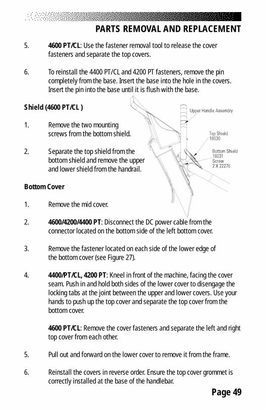
Page 49
5. 4600 PT/CL: Use the fastener removal tool to release the coverfasteners and separate the top covers.
6. To reinstall the 4400 PT/CL and 4200 PT fasteners, remove the pincompletely from the base. Insert the base into the hole in the covers.Insert the pin into the base until it is flush with the base.
Shield (4600 PT/CL )
1. Remove the two mountingscrews from the bottom shield.
2. Separate the top shield from thebottom shield and remove the upperand lower shield from the handrail.
Bottom Cover
1. Remove the mid cover.
2. 4600/4200/4400 PT: Disconnect the DC power cable from theconnector located on the bottom side of the left bottom cover.
3. Remove the fastener located on each side of the lower edge ofthe bottom cover (see Figure 27).
4. 4400/PT/CL, 4200 PT: Kneel in front of the machine, facing the coverseam. Push in and hold both sides of the lower cover to disengage thelocking tabs at the joint between the upper and lower covers. Use yourhands to push up the top cover and separate the top cover from thebottom cover.
4600 PT/CL: Remove the cover fasteners and separate the left and righttop cover from each other.
5. Pull out and forward on the lower cover to remove it from the frame.
6. Reinstall the covers in reverse order. Ensure the top cover grommet iscorrectly installed at the base of the handlebar.
PARTS REMOVAL AND REPLACEMENT
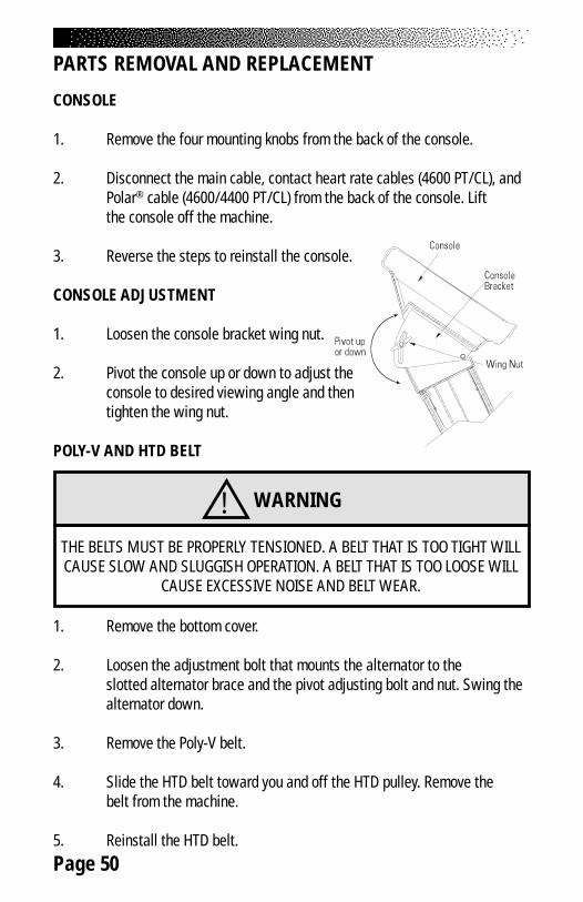
Page 50
CONSOLE
1. Remove the four mounting knobs from the back of the console.
2. Disconnect the main cable, contact heart rate cables (4600 PT/CL), andPolar® cable (4600/4400 PT/CL) from the back of the console. Liftthe console off the machine.
3. Reverse the steps to reinstall the console.
CONSOLE ADJUSTMENT
1. Loosen the console bracket wing nut.
2. Pivot the console up or down to adjust theconsole to desired viewing angle and thentighten the wing nut.
POLY-V AND HTD BELT
1. Remove the bottom cover.
2. Loosen the adjustment bolt that mounts the alternator to theslotted alternator brace and the pivot adjusting bolt and nut. Swing thealternator down.
3. Remove the Poly-V belt.
4. Slide the HTD belt toward you and off the HTD pulley. Remove thebelt from the machine.
5. Reinstall the HTD belt.
PARTS REMOVAL AND REPLACEMENT
! WARNING
THE BELTS MUST BE PROPERLY TENSIONED. A BELT THAT IS TOO TIGHT WILLCAUSE SLOW AND SLUGGISH OPERATION. A BELT THAT IS TOO LOOSE WILL
CAUSE EXCESSIVE NOISE AND BELT WEAR.
Page 51
6. Adjust the HTD belt tension so that you have 1/4 inch (0.6 cm) of side-to-side play with fingertip pressure (see Figure 30). The bottom shaft ismounted in an eccentric hub. To adjust the tension:
• Loosen and remove the four bolts and nyloc nuts from the hub.• Turn the hub one hole clockwise.• Install and tighten the four bolts and nyloc nuts.• Verify the HTD belt tension.
7. Install the Poly-V belt. Make sure it is centered on the pulleys.
8. Pivot the alternator up or down as necessary to allow 1/4"(0.6 cm) of belt deflection with fingertip pressure at the center of thevertical portion of either side of the belt (see Figure 30).
9. Tighten the alternator adjustment bolt. Verify 1/4" (0.6 cm) of playin the belt and reinstall the bottom cover.
STEP CHAIN RETAINER
1. Remove the bottom cover.
2. Loosen and remove the two step chain retainer bolts. These bolts arealso the top two mounting bolts for the drive hub assembly.
3. Reverse the removal procedures to install the step chain retainer. Makesure there is adequate clearance between the step chain and the stepchain retainer.
PEDAL ARM RETURN SPRING
1. Remove the bottom cover.
2. Unhook the pedal arm return spring from the spring hanger.
3. Detach the spring from the step chain by removing the master link. Thespring-chain connector is in good condition if it has an hour glassshape. Replace a worn spring-chain connector.
PARTS REMOVAL AND REPLACEMENT
Page 52
4. Check to ensure that the spring pulley turns freely and is not wornexcessively. Refer to the “Spring Pulley” section if you have to replacethe pulley.
5. To reinstall the spring, connect it to the end of the step chain using themaster link.
6. Route the spring under the spring pulley that is fastened to the springpulley shaft (see Figure 10).
7. Hook the end of the pedal arm return spring onto the spring hanger.
8. Reinstall the covers.
STEP CHAIN
1. Remove the bottom cover.
2. Remove the step chain retainers.
3. Support the pedal arm. Unhook the pedal arm return spring from thespring hanger. Lift the step chain up and off the clutch sprocket andlower the pedal arm to the floor.
4. Remove the double-pitch master link (PN 21298SV) and bearing sleeveassembly from the step chain connection point on the pedal arm.
5. Remove the master link from the spring-chain connection.
6. Reverse the procedures to reinstall the step chain. Lubricate the stepchain before reinstalling the covers.
PARTS REMOVAL AND REPLACEMENT
! WARNING
DO NOT TWIST THE SPRING DURING INSTALLATION. IT WILL WEAREXCESSIVELY AND REDUCE THE LIFE OF THE SPRING.
Page 53
SPRING PULLEY
1. Remove the bottom cover.
2. Unhook the pedal arm return spring from the spring hanger.
3. Remove the snap ring from the pulley shaft (see Figure 10).
4. Slide the pulley and washer off the shaft.
5. Before reinstalling the pulley, clean the pulley shaft thoroughly with aclean, dry cloth. Apply a thin coat of multi-purpose grease to the pulleyshaft.
6. Slide the pulley and washer onto the shaft. Install the snap ring.
7. Route the spring under the spring pulley.
8. Hook the end of the spring over the spring hanger. Do not twist thespring.
9. Reinstall the covers.
DRIVE CHAIN
1. Remove the bottom cover.
PARTS REMOVAL AND REPLACEMENT
TO REDUCE THE RISK OF EYE INJURY, WEAR EYEPROTECTION WHEN REMOVING SNAP RINGS.
! WARNING
! WARNING
DO NOT TWIST THE SPRING DURING INSTALLATION. IT WILL WEAREXCESSIVELY AND REDUCE THE LIFE OF THE SPRING.
Page 54
TO REDUCE THE RISK OF EYE INJURY, WEAR EYEPROTECTION WHEN REMOVING SNAP RINGS.
! WARNING
2. Remove the master link from the drive chain.
3. Remove the drive chain from the sprockets.
4. Reinstall the drive chain, ensuring the master link is properly installed.
5. Check the drive chain tension. There should be a total of 1 to1-1/2" (2.5 to 4.0 cm) of play, up and down, at the slackest point in thechain (see Figure 29). If the drive chain tension needs adjustment, referto the “Drive Hub Assembly” section.
6. Lubricate the chain with 30W motor oil and wipe off the excess.
7. Reinstall the covers.
DRIVE SHAFT ASSEMBLY
1. Remove the bottom cover.
2. Remove the step chain retainers.
3. Support the pedal arm. Unhook the pedal arm return spring from thespring hanger. Lift the step chain up and off the clutch sprocket andlower the pedal arm to the floor. Repeat on the other side.
4. Remove the snap ring from the left end of the drive shaft.
PARTS REMOVAL AND REPLACEMENT
! WARNING
IF THE DRIVE CHAIN IS TOO TIGHT, THE DRIVE TRAIN WILL WEAREXCESSIVELY, SHORTENING THE LIFE OF THE DRIVE HUB. IF THECHAIN IS TOO LOOSE, THE MACHINE WILL BE NOISY AND WILL
OPERATE AT LESS THAN PEAK EFFICIENCY.
Page 55
5. Remove the drive chain.
6. Remove the sprocket and the other small parts from the left side of thehub assembly (see Figure 21).
7. Slide the drive shaft to the right, out of the hub assembly. If you removethe right-hand clutch sprocket from the drive shaft, do not confuse itwith the left-hand clutch sprocket.
8. Loosen and remove the two remaining bolts and nuts that hold the hubassembly to the frame. Remove the hub assembly.
9. Inspect the drive shaft, the bushings, the thrust washers, and clutchsprockets for excessive wear or pitting. Replace worn-out components.
10. To reinstall the hub assembly, carefully reverse the disassemblyprocedures. Be sure that the right- and left-hand clutch sprockets arepositioned correctly; the wide shoulder of the sprocket should be facingaway from the hub on both sides.
11. Chain Tension. The drive shaft is mounted in an eccentric hub. Rotatethe hub so the marked hole is in the 12 o’clock position, lining up fourholes in the hub with the four holes in the frame. Use this hub positionwhen reinstalling the drive chain since the distance between the driveand transmission shafts is at a minimum. The hub is in the properposition when the drive chain has a total of 1 to 1-1/2" (2.5 to 4.0 cm) ofplay at the slackest point. As the drive chain stretches with use,increase the chain tension (and the distance between the two shafts)by rotating the hub counterclockwise (see Figure 29). The distancebetween the two shafts is greatest when the marked hole in the hub isat the 8 o’clock position.
12. Reinstall the covers.
PARTS REMOVAL AND REPLACEMENT
Page 56
PEDAL
1. Remove the snap ring and flat washer from the leveling arm pin and thepedal shaft (see Figure 20).
2. Slide the pedal off the shaft.
3. Clean the pedal shaft and leveling arm pin with a dry cloth. Lubricatethe pedal shaft and the leveling arm pin with a thin coat of multi-purpose grease.
4. Reverse the procedures to reinstall the pedal.
LEVELING ARM
1. Remove the pedal.
2. Remove the bottom cover.
3. Remove the snap ring that secures the leveling arm to the leveling armshaft (see Figure 18).
4. Slide or gently tap the leveling arm off the shaft.
5. Clean the shaft and the pin with a cloth dampened with 30W motor oilbefore reassembly.
6. Reverse the removal instructions to reinstall the leveling arm.
PARTS REMOVAL AND REPLACEMENT
TO REDUCE THE RISK OF EYE INJURY, WEAR EYEPROTECTION WHEN REMOVING SNAP RINGS.
! WARNING
TO REDUCE THE RISK OF EYE INJURY, WEAR EYEPROTECTION WHEN REMOVING SNAP RINGS.
! WARNING
Page 57
PEDAL ARM
1. Remove the pedal and the bottom cover.
2. Remove the step chain retainers.
3. Support the pedal arm. Unhook the pedal arm return spring from thespring hanger. Lift the step chain up and off the clutch sprocket andlower the pedal arm to the floor.
4. Remove the master link from the step chain connection point.
5. Remove the snap ring from the pedal arm mounting shaft and theleveling arm pin.
6. Slide or gently tap the pedal arm off the mounting shaft.
7. Clean the pedal arm shaft and leveling arm pin with a cloth dampenedwith 30W motor oil before reassembly.
8. Reverse the removal procedures to reinstall the pedal arm.
PEDAL PAD
1. The pedal pad wraps around the pedal and locks into place under thepedal. Separate the pedal pad from the pedal by grabbing the bottom ofthe pedal and pulling down and out.
2. Lift the other side of the pedal pad up and remove the pedal pad fromthe pedal.
Note: There is a right and left pedal pad. Do not install a leftpedal pad on a right pedal, or a right pedal pad on a left pedal.
PARTS REMOVAL AND REPLACEMENT
TO REDUCE THE RISK OF EYE INJURY, WEAR EYEPROTECTION WHEN REMOVING SNAP RINGS.
! WARNING
Page 58
PARTS REMOVAL AND REPLACEMENT
ECCENTRIC HUB ASSEMBLY
1. Remove the bottom cover.
2. Remove the Poly-V and HTD belts.
3. Loosen and remove the four nyloc nuts and bolts from the hub. Removethe assembly from the frame.
4. Reassemble in the reverse order. Ensure the belts are properlytensioned; refer to the "Poly-V and HTD belt" section.
FIRST REDUCTION SHAFT ASSEMBLY
1. Remove the bottom cover.
2. Remove the drive chain.
3. Remove the eccentric shaft assembly.
4. Remove the set screw from the transmission sprocket (see Figure 20).Remove the sprocket and key from the shaft.
5. Hold onto the HTD sprocket and pull the shaft out of the hub.
6. Reassemble in the reverse order. Ensure the belts are properlytensioned; refer to the "Poly-V and HTD belt" section.
HANDLEBAR (4400 PT/CL ,4200 PT)
1. Remove the console and separate the left and right top cover.
2. Cut the Ty-wraps that secure the main cable to the handlebar tube.
3. Remove the four screws and flat washers that hold the handlebar tubein the frame tube (see Final Assembly Figure).
4. Lift the handlebar out of the frame. Reverse the steps to reinstall thehandlebars.
Page 59
UPPER HANDLES (4600 PT/CL)
1. Disconnect the left and right contact heart rate cables from the back ofthe console.
2. Remove the two mounting screws from the top and bottom shield (seeFigure 19) and remove the shields from the upper handle assembly.
3. Remove the four handrail adapter screws from the upper handleassembly.
4. Remove the upper handle assembly from the machine. The contactheart rate cables are threaded through the handrail adapter. Removethe handrail adapter from the contact heart rate cables.
5. Reverse the removal procedures to install the new upper handleassembly.
SIDE HANDRAILS (4600 PT/CL)
1. Disconnect the left and rightcontact heart rate cablesfrom the back of the console.
2. Remove the two mountingscrews from the top and bottomshield (see Figure 19) and removethe shields from the upper handleassembly.
3. Remove the four handrailadapter screws from the upperhandle assembly.
4. Remove the upper handle assembly from themachine. The contact heart rate cables arethreaded through the handrail adapter. Remove thehandrail adapter from the contact heart rate cables.Set the upper handle assembly aside.
PARTS REMOVAL AND REPLACEMENT
Page 60
PARTS REMOVAL AND REPLACEMENT
5. Tilt the machine forward and use an extended socket to remove thetwo handrail adapter screws from the front leg of the machine.
6. Tilt the machine back into place and pull each handrail out sideways.Be aware that the handrail extrusion connects the left handrail to theright handrail, and may fall out when one side is removed.
7. Reverse the removal procedures to reinstall the handrail.
ALTERNATOR
1. Remove the bottom cover. Mark (by color) the location of each wireattached to the alternator (see Final Assembly Diagram). Remove thewires from the alternator.
2. Loosen and remove the alternator adjusting bolt on the slotted brace.Remove the Poly-V belt. Inspect the belt for wear and replace the belt ifit is cracked, cut, or is otherwise damaged.
3. Loosen and remove the nyloc nut from the alternator post. Remove thealternator from the frame.
4. Reverse the removal procedures to install the new alternator. Be sure toverify the wiring against the Final Assembly Diagram.
5. Pivot the alternator up or down as necessary to allow 1/4"(0.6 cm) of belt deflection with finger tip pressure at the center of thevertical portion of either side of the belt (see Figure 30).
Page 61
The machine must be grounded if you are using the external power supply or thebattery charger. Grounding provides the path of least resistance for the electriccurrent, thereby reducing the risk of electric shock. The power supply or batterycharger must be plugged into an appropriate outlet that is properly installed andgrounded in accordance with all local codes and ordinances.
The grounding plug on the power supply and the battery charger isshown in sketch A below*. A temporary adapter, shown in sketches B and C, maybe used to connect the plug to a two-pole receptacle if a properly grounded out-let is not available. The adapter should be used only until a properly groundedoutlet (sketch A) can be installed by a qualified electrician. The tab extendingfrom the adapter must be connected to a permanent ground such as the metalscrew on the outlet cover.
* This may vary for International power supplies.
GROUNDING INSTRUCTIONS
Figure 9: Grounding System
! DANGER
IMPROPER CONNECTION OF THE EQUIPMENT-GROUNDING CONNECTOR CANRESULT IN THE RISK OF ELECTRIC SHOCK. CHECK WITH A QUALIFIED ELECTRI-CIAN OR SERVICE PERSON IF YOU ARE IN DOUBT AS TO WHETHER THE MA-CHINE IS PROPERLY GROUNDED. DO NOT MODIFY THE PLUG PROVIDED WITHTHIS MACHINE. IF IT WILL NOT FIT THE AVAILABLE OUTLET, HAVE A PROPER
OUTLET INSTALLED BY A QUALIFIED ELECTRICIAN.
Page 62
This equipment has been tested and found to comply with the limits for a Class Bdigital device, pursuant to Part 15 of the FCC rules. These limits are designed toprovide reasonable protection against harmful interference in a residential instal-lation. This equipment generates, uses and can radiate radio frequency energyand, if not installed and used in accordance with the instructions, may causeharmful interference to radio communications. However, there is no guaranteethat interference will not occur in a particular installation. If this equipment doescause harmful interference to radio or television reception, which can be deter-mined by turning the equipment off and on, the user is encouraged to try to cor-rect the interference by one or more of the following measures:
• Reorient or relocate the receiving antenna.• Increase the separation between the equipment and receiver.• Connect the equipment into an outlet on a circuit different from
that to which the receiver is connected.• Consult the dealer or an experienced radio/TV technician for help.
CANADIAN DOC CLASS B COMPLIANCE
This digital apparatus does not exceed the Class B limits for radio emissions fromdigital apparatus set out in the radio interference regulations of the CanadianDepartment of Communications.
La présent appareil numérique ne dépasse pas les limites etablies pour les bruitsradioélectriques applicables aux appareils numériques de la Class B prescritesdans les règlement sur le brouillage radioélectrique édicté par le Ministère desCommunications du Canada.
FCC COMPLIANCE
! WARNING
CHANGES OR MODIFICATIONS TO EQUIPMENT NOTEXPRESSLY APPROVED BY STAIRMASTER® SPORTS/MEDICAL
PRODUCTS, INC. COULD VOID THE USER'S AUTHORITY TOOPERATE THIS EQUIPMENT.

Page 63
IMPORTANT PHONE NUMBERS
If you need assistance, please have both the serial number of your machine andthe date of purchase available when you contact the appropriate StairMaster®
Sports/Medical Products, Inc. office listed below.
OFFICES IN THE UNITED STATES
CORPORATE HEADQUARTERS CUSTOMER SERVICE12421 Willows Road NE, Suite 100 12421 Willows Road NE, Suite 100Kirkland, WA 98034 Kirkland, WA 98034(800) 635-2936 or (425) 823-1825 (800) 331-3578FAX: (425) 823-9490 FAX: (425) 814-0601
INTERNATIONAL OFFICES AND DISTRIBUTORS
For technical assistance and a list of distributors in your area, please call or faxone of the following numbers.
INTERNATIONAL DIVISION(425) 823-1825FAX: (425) 820-7505
EUROPE: HEADQUARTERS41-91-827-3801FAX: 41-91-827-8902
GERMANY: HEADQUARTERS49-2204/610-27FAX: 49-2204/628-90
U.K.: HEADQUARTERS44-1908/221-323FAX: 44-1908/223-162
Page 64
After installing a new battery, you will need to properly dispose of (recycle) yourold lead-acid battery. Most federal and state regulations require lead-acid batter-ies be recycled. Do not throw away old batteries. Lead is a heavy metal and istoxic to living organisms. Contact the nearest Yuasa-Exide, Inc. recycling centerfrom the list below to get information on the proper disposal of your old lead-acidbattery.
STATE ADDRESS PHONE NUMBER
Alabama 906 40th St. (205) 591-0606Birmingham, AL 35222
California, 3470 Depot Rd. (510) 887-8080 (Northern) Hayward, CA 94545 California, 1250 Bixby Dr. (818) 333-3060 (Southern) City of Industry, CA 91745 Colorado 12860 W. Cedar Dr. (303) 763-5833
Suite 106ALakewood, CO 80228
Florida 11310 Satellite Blvd. (407) 857-9234Orlando, FL 32821
Georgia 1721-C Oakbrook Dr. NE (404) 446-8663Norcross, GA 30093
Illinois 5303 Ninth Ave (708) 352-3665Countryside, IL 60525
Maryland 899 Airport Rd. Ste E (410) 768-5586Glen Burnie, MD 21061
Massachusetts 13 Wheeling Ave. (617) 932-6570Woburn, MA 01801
Michigan, 2760 Auburn Rd. (616) 531-1120 Southeast Auburn Hills, MI 48326 Michigan, West 2882 Remico St. SW (612) 631-2150
Grandville, MI 49418 Minnesota 1900 Oakcrest Ave. Ste 5 (816) 231-1414
Roseville, MN 55113 Missouri 5328 Winner Rd. (816) 231-0685
Kansas City, MO 64127 New Hampshire 17 Clinton Dr. (603) 886-5900
Hollis, NH 03049
○
○
○
○
○
○
○
○
○
○
○
○
○
○
○
○
○
○
○
○
○
○
○
○
○
○
○
○
○
○
○
○
○
○
○
○
○
○
○
○
○
○
○
○
○
○
○
○
○
○
○
○
○
○
○
○
○
○
○
○
○
○
○
○
○
○
○
○
○
○
○
○
○
○
○
○
○
○
○
○
○
○
○
○
○
○
○
○
○
○
○
○
○
○
○
○
○
○
○
○
○ ○ ○ ○ ○ ○ ○ ○ ○ ○ ○ ○ ○ ○ ○ ○ ○ ○ ○ ○ ○ ○ ○ ○ ○ ○ ○ ○ ○ ○ ○ ○ ○ ○ ○ ○ ○ ○ ○ ○ ○
○ ○ ○ ○ ○ ○ ○ ○ ○ ○ ○ ○ ○ ○ ○ ○ ○ ○ ○ ○ ○ ○ ○ ○ ○ ○ ○ ○ ○ ○ ○ ○ ○ ○ ○ ○ ○ ○ ○ ○ ○
○ ○ ○ ○ ○ ○ ○ ○ ○ ○ ○ ○ ○ ○ ○ ○ ○ ○ ○ ○ ○ ○ ○ ○ ○ ○ ○ ○ ○ ○ ○ ○ ○ ○ ○ ○ ○ ○ ○ ○ ○
○ ○ ○ ○ ○ ○ ○ ○ ○ ○ ○ ○ ○ ○ ○ ○ ○ ○ ○ ○ ○ ○ ○ ○ ○ ○ ○ ○ ○ ○ ○ ○ ○ ○ ○ ○ ○ ○ ○ ○ ○
○ ○ ○ ○ ○ ○ ○ ○ ○ ○ ○ ○ ○ ○ ○ ○ ○ ○ ○ ○ ○ ○ ○ ○ ○ ○ ○ ○ ○ ○ ○ ○ ○ ○ ○ ○ ○ ○ ○ ○ ○
○ ○ ○ ○ ○ ○ ○ ○ ○ ○ ○ ○ ○ ○ ○ ○ ○ ○ ○ ○ ○ ○ ○ ○ ○ ○ ○ ○ ○ ○ ○ ○ ○ ○ ○ ○ ○ ○ ○ ○ ○
○ ○ ○ ○ ○ ○ ○ ○ ○ ○ ○ ○ ○ ○ ○ ○ ○ ○ ○ ○ ○ ○ ○ ○ ○ ○ ○ ○ ○ ○ ○ ○ ○ ○ ○ ○ ○ ○ ○ ○ ○
○ ○ ○ ○ ○ ○ ○ ○ ○ ○ ○ ○ ○ ○ ○ ○ ○ ○ ○ ○ ○ ○ ○ ○ ○ ○ ○ ○ ○ ○ ○ ○ ○ ○ ○ ○ ○ ○ ○ ○ ○
○ ○ ○ ○ ○ ○ ○ ○ ○ ○ ○ ○ ○ ○ ○ ○ ○ ○ ○ ○ ○ ○ ○ ○ ○ ○ ○ ○ ○ ○ ○ ○ ○ ○ ○ ○ ○ ○ ○ ○ ○
○ ○ ○ ○ ○ ○ ○ ○ ○ ○ ○ ○ ○ ○ ○ ○ ○ ○ ○ ○ ○ ○ ○ ○ ○ ○ ○ ○ ○ ○ ○ ○ ○ ○ ○ ○ ○ ○ ○ ○ ○
○ ○ ○ ○ ○ ○ ○ ○ ○ ○ ○ ○ ○ ○ ○ ○ ○ ○ ○ ○ ○ ○ ○ ○ ○ ○ ○ ○ ○ ○ ○ ○ ○ ○ ○ ○ ○ ○ ○ ○ ○
○ ○ ○ ○ ○ ○ ○ ○ ○ ○ ○ ○ ○ ○ ○ ○ ○ ○ ○ ○ ○ ○ ○ ○ ○ ○ ○ ○ ○ ○ ○ ○ ○ ○ ○ ○ ○ ○ ○ ○ ○
○ ○ ○ ○ ○ ○ ○ ○ ○ ○ ○ ○ ○ ○ ○ ○ ○ ○ ○ ○ ○ ○ ○ ○ ○ ○ ○ ○ ○ ○ ○ ○ ○ ○ ○ ○ ○ ○ ○ ○ ○
BATTERY RECYCLING CENTERS
Page 65
STATE ADDRESS PHONE NUMBER
New Jersey 131 Industrial Ave. (201) 641-5900Hasbrouck Hgts., NJ 07604
New York 26 Corporate Circle (315) 437-1788E. Syracuse, NY 13057
Ohio, Central Rickenbacker ANG (513) 851-3838Bldg. 1073Columbus, OH 43217
Ohio, North 2635 Hamilton Ave. (216) 241-6231Cleveland, OH 44114
Ohio, Southwest 540 Northland Blvd. (216) 241-6231Cincinnati, OH 45240
Pennsylvania, East 3000 Montrose Ave. (215) 921-4480Laureldale, PA 19605
Pennsylvania, East 320 Constance Dr. (215) 443-0912Warminster, PA 18974
Pennsylvania, West 920 Vista Park Rd. (412) 788-1613Pittsburgh, PA 15205
Tennessee 2934 Brooks Road (901) 396-5031Memphis, TN 38116
Texas, Northeast 11420 Ferrell Dr. Ste 300 (214) 869-1855Dallas, TX 75234
Texas,South 4738 Cotton Belt (210) 661-5497San Antonio, TX 78219
Texas, Southeast 4301 S. Pinemont Ste 114 (713) 690-8700Houston, TX 77041
Washington 660 Industry Dr. (425) 575-3090Tukwila, WA 98188
West Virginia P.O. Box 1666 (304) 327-3594Rte. 2, Box 1Bluefield, WV 24701
○
○
○
○
○
○
○
○
○
○
○
○
○
○
○
○
○
○
○
○
○
○
○
○
○
○
○
○
○
○
○
○
○
○
○
○
○
○
○
○
○
○
○
○
○
○
○
○
○
○
○
○
○
○
○
○
○
○
○
○
○
○
○
○
○
○
○
○
○
○
○
○
○
○
○
○
○
○
○
○
○
○
○
○
○
○
○
○
○
○
○
○
○
○
○
○
○
○
○
○
○
○
○
○
○ ○ ○ ○ ○ ○ ○ ○ ○ ○ ○ ○ ○ ○ ○ ○ ○ ○ ○ ○ ○ ○ ○ ○ ○ ○ ○ ○ ○ ○ ○ ○ ○ ○ ○ ○ ○ ○ ○ ○ ○
○ ○ ○ ○ ○ ○ ○ ○ ○ ○ ○ ○ ○ ○ ○ ○ ○ ○ ○ ○ ○ ○ ○ ○ ○ ○ ○ ○ ○ ○ ○ ○ ○ ○ ○ ○ ○ ○ ○ ○ ○
○ ○ ○ ○ ○ ○ ○ ○ ○ ○ ○ ○ ○ ○ ○ ○ ○ ○ ○ ○ ○ ○ ○ ○ ○ ○ ○ ○ ○ ○ ○ ○ ○ ○ ○ ○ ○ ○ ○ ○ ○
○ ○ ○ ○ ○ ○ ○ ○ ○ ○ ○ ○ ○ ○ ○ ○ ○ ○ ○ ○ ○ ○ ○ ○ ○ ○ ○ ○ ○ ○ ○ ○ ○ ○ ○ ○ ○ ○ ○ ○ ○
○ ○ ○ ○ ○ ○ ○ ○ ○ ○ ○ ○ ○ ○ ○ ○ ○ ○ ○ ○ ○ ○ ○ ○ ○ ○ ○ ○ ○ ○ ○ ○ ○ ○ ○ ○ ○ ○ ○ ○ ○
○ ○ ○ ○ ○ ○ ○ ○ ○ ○ ○ ○ ○ ○ ○ ○ ○ ○ ○ ○ ○ ○ ○ ○ ○ ○ ○ ○ ○ ○ ○ ○ ○ ○ ○ ○ ○ ○ ○ ○ ○
○ ○ ○ ○ ○ ○ ○ ○ ○ ○ ○ ○ ○ ○ ○ ○ ○ ○ ○ ○ ○ ○ ○ ○ ○ ○ ○ ○ ○ ○ ○ ○ ○ ○ ○ ○ ○ ○ ○ ○ ○
○ ○ ○ ○ ○ ○ ○ ○ ○ ○ ○ ○ ○ ○ ○ ○ ○ ○ ○ ○ ○ ○ ○ ○ ○ ○ ○ ○ ○ ○ ○ ○ ○ ○ ○ ○ ○ ○ ○ ○ ○
○ ○ ○ ○ ○ ○ ○ ○ ○ ○ ○ ○ ○ ○ ○ ○ ○ ○ ○ ○ ○ ○ ○ ○ ○ ○ ○ ○ ○ ○ ○ ○ ○ ○ ○ ○ ○ ○ ○ ○ ○
○ ○ ○ ○ ○ ○ ○ ○ ○ ○ ○ ○ ○ ○ ○ ○ ○ ○ ○ ○ ○ ○ ○ ○ ○ ○ ○ ○ ○ ○ ○ ○ ○ ○ ○ ○ ○ ○ ○ ○ ○
○ ○ ○ ○ ○ ○ ○ ○ ○ ○ ○ ○ ○ ○ ○ ○ ○ ○ ○ ○ ○ ○ ○ ○ ○ ○ ○ ○ ○ ○ ○ ○ ○ ○ ○ ○ ○ ○ ○ ○ ○
○ ○ ○ ○ ○ ○ ○ ○ ○ ○ ○ ○ ○ ○ ○ ○ ○ ○ ○ ○ ○ ○ ○ ○ ○ ○ ○ ○ ○ ○ ○ ○ ○ ○ ○ ○ ○ ○ ○ ○ ○
○ ○ ○ ○ ○ ○ ○ ○ ○ ○ ○ ○ ○ ○ ○ ○ ○ ○ ○ ○ ○ ○ ○ ○ ○ ○ ○ ○ ○ ○ ○ ○ ○ ○ ○ ○ ○ ○ ○ ○ ○
BATTERY RECYCLING CENTERS
Page 66
FIGURES
Figure 10: Parts Needing Periodic Maintenance
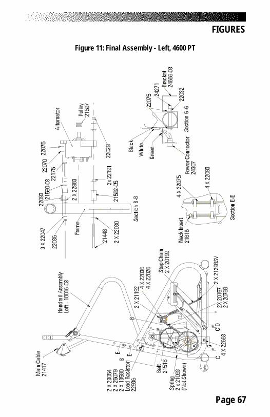
Page 67
FIGURES
Figure 11: Final Assembly - Left, 4600 PT
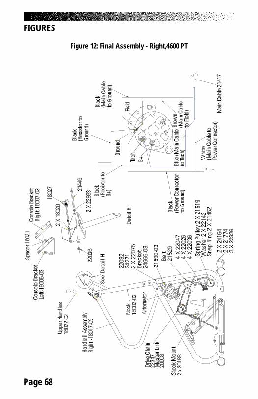
Page 68
FIGURES
Figure 12: Final Assembly - Right,4600 PT
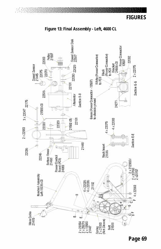
Page 69
FIGURES
Figure 13: Final Assembly - Left, 4600 CL
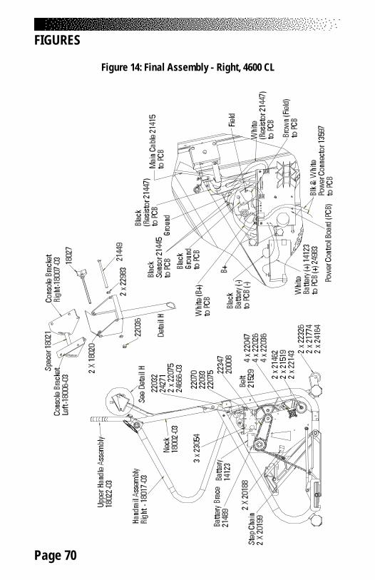
Page 70
FIGURES
Figure 14: Final Assembly - Right, 4600 CL
Page 71
FIGURES
Figure 15: Covers - 4600 PT/CL
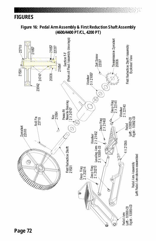
Page 72
FIGURES
Figure 16: Pedal Arm Assembly & First Reduction Shaft Assembly(4600/4400 PT/CL, 4200 PT)
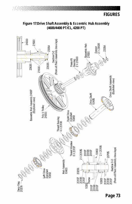
Page 73
FIGURES
Figure 17:Drive Shaft Assembly & Eccentric Hub Assembly(4600/4400 PT/CL, 4200 PT)
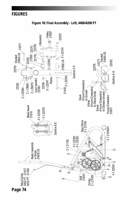
Page 74
FIGURES
Figure 18: Final Assembly - Left, 4400/4200 PT
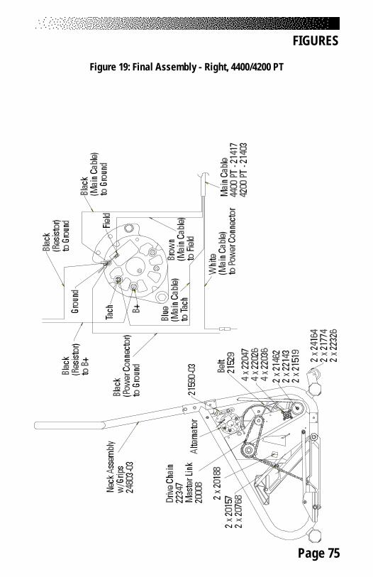
Page 75
FIGURES
Figure 19: Final Assembly - Right, 4400/4200 PT
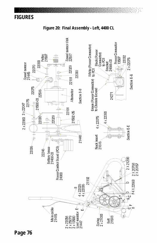
Page 76
FIGURES
Figure 20: Final Assembly - Left, 4400 CL
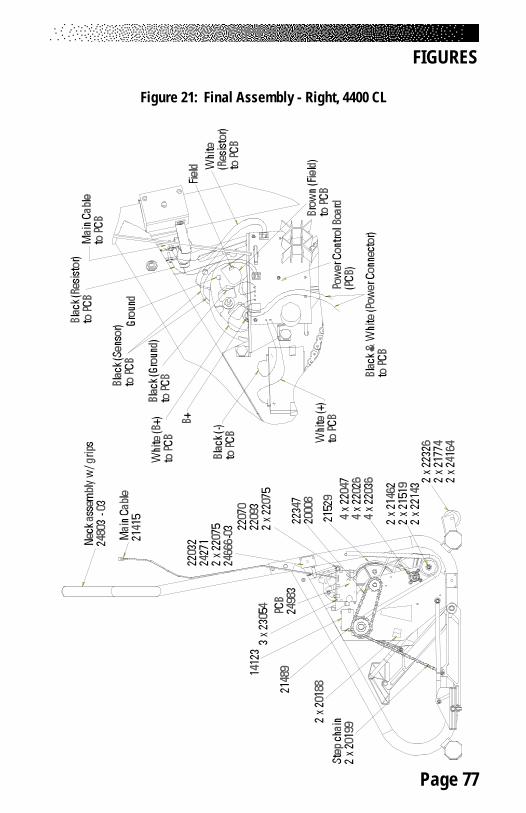
Page 77
FIGURES
Figure 21: Final Assembly - Right, 4400 CL
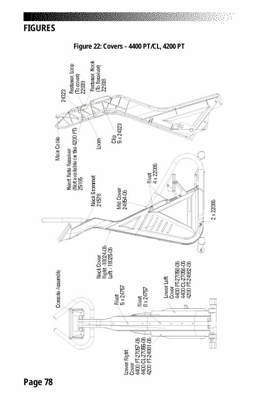
Page 78
FIGURES
Figure 22: Covers - 4400 PT/CL, 4200 PT
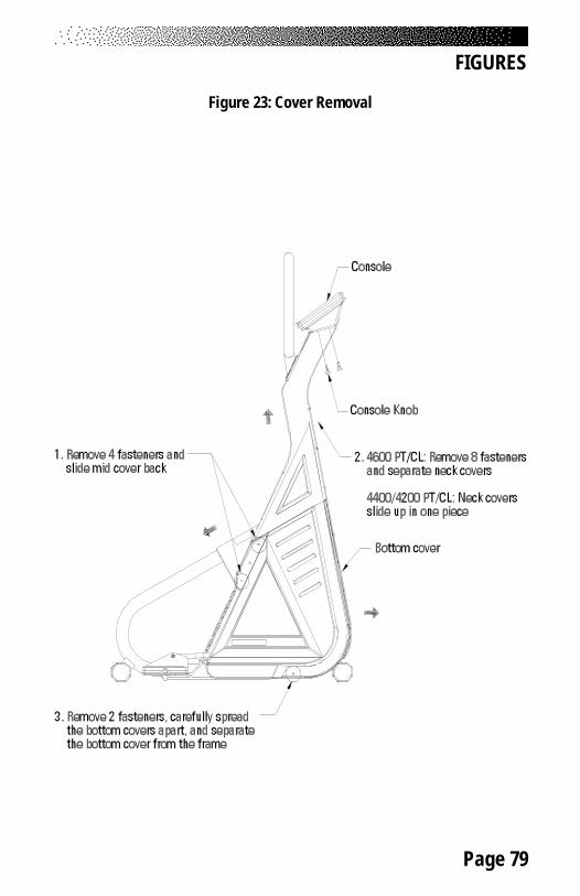
Page 79
FIGURES
Figure 23: Cover Removal
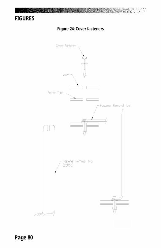
Page 80
Figure 24: Cover fasteners
FIGURES
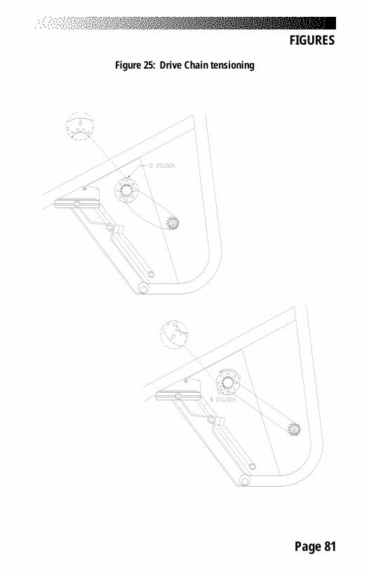
Page 81
FIGURES
Figure 25: Drive Chain tensioning
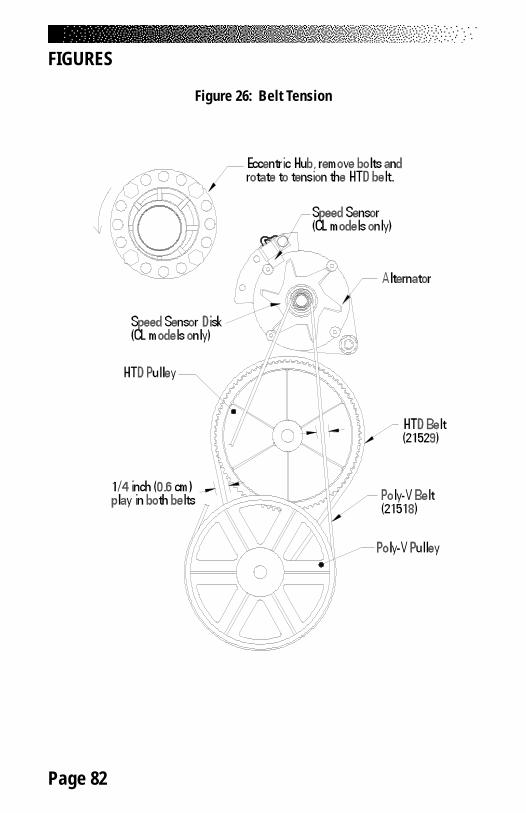
Page 82
FIGURES
Figure 26: Belt Tension