Embed Size (px)
Citation preview
FREE VIBRATION ANALYSIS OF SANDWICH PANEL
A THESIS SUBMITTED IN PARTIAL FULFILLMENT OF THE REQUIREMENTS FOR THE DEGREE OF
Master of Technology
in
Mechanical Engineering
By
AMIT KUMAR JHA
Department of Mechanical Engineering National Institute of Technology
Rourkela 2007

FREE VIBRATION ANALYSIS OF SANDWICH PANEL
A THESIS SUBMITTED IN PARTIAL FULFILLMENT OF THE
REQUIREMENTS FOR THE DEGREE OF
Master of Technology
in
Mechanical Engineering
By
AMIT KUMAR JHA
Under the guidance of
Prof. N.KAVI
Department of Mechanical Engineering National Institute of Technology
Rourkela 2007
National Institute of Technology Rourkela
CERTIFICATE
This is to certify that the thesis entitled “FREE VIBRATION ANALYSIS OF
SANDWICH PANEL” submitted by Sri Amit Kumar Jha in partial fulfillment of the
requirements for the award of Master of Technology Degree in Mechanical Engineering at
the National Institute of Technology, Rourkela (Deemed University) is an authentic work
carried out by him under my supervision and guidance.
To the best of my knowledge, the matter embodied in the thesis has not been
submitted to any other University / Institute for the award of any Degree or Diploma.
Mr. A. Ramamoorthy Hindustan Aeronautics Limited Bangalore-560017
Prof. N. Kavi National Institute of Technology Rourkela-769008

ACKNOWLEDGEMENT
I would like to express my deep sense of profound gratitude to my guide, Prof. N.
Kavi for his guidance and constant support.
I extend my thank to our HOD, Dr. B. K. Nanda for his valuable advices and
encouragement.
I would like to thank Mr. A. Ramamoorthy (CM Production, Aircraft Division and
Bangalore) for his guidance and constant support.
I would like to thank all HAL officers/employees who are supported me in carrying
out the project work in the organization.
I would like to thank to all those who are directly or indirectly supported me in
carrying out this thesis work successfully.
Amit Kumar Jha Roll No. 20503002 Department of Mechanical Engg National Institute of Technology Rourkela
i

CONTENTS
Acknowledgment………………………………………………………………………..i
Contents………………………………………………………………………………..ii
Abstract………………………………………………………………………………. iv
List of figures………………………………………………………………………….v
List of tables…………………………………………………………………………..vii
1. Introduction
1.1 Types of sandwich panel ……………………………………………….2
1.2 Sandwich construction ………………………………………………….2
1.3 Selection of sandwich composite structure ……………………………..6
1.4 Current application ………………………………………………….......6
2. Literature survey
2.1 Truss core sandwich ……………………………………………………10
2.2Optimization of sandwich material ………………………………………10
2.3 Global higher theory …………………………………………………….11
3. Finite element formulation
3.1 Theory …………..………………………………………………………12
3.2 Shear deformation of the plate ………………………………………….14
3.3 Constitutive equation for anisotropic plate ……………………………...18
3.4 Constitutive equation for laminated plate …………………………. ........19
3.5 Finite element formulation ……………………………………………….21
3.6 Vibration solution technique ……………………………………………..24
4. Macro mechanical behavior of laminate
4.1 Introduction …………………………………………………………........27
4.2 Macro mechanical behavior ………………………………………………27
5. Bending of laminated plate
5.1 Introduction ……………………………………………………………….35
ii

5.2 Thin laminated plate theory ………………………………………………35
5.3 Free vibration of laminated plate …………………………………………38
6. Sandwich structure
6.1 Sandwich principle ………………………………………………………..43
6.2 Stiffness to weight ratio of sandwich plate ……………………………… 44
7. Results and discussion of isotropic plate
7.1 Experimental results ……………………………………………………...46
7.2 Finite element package (ANSYS) results ………………………………. 49
7.3 Comparison of experimental work and FEA work with analytical
solution …………………………………………………………………..51
7.4 Effect of aspect ratio on natural frequency ………………………………52
7.5 Effect of change of dimension on natural frequency …………………….53
8. Results and discussions of sandwich plate
8.1 Experimental results ………………………………….............................55
8.2 Finite element package (ANSYS) results ……………………………….56
8.3 Comparison of FEA (ANSYS) with analytical solution, experimental
work and FEA (MSC/NASTRAN) ………………………………………58
8.4 Study of comparison between sandwich plate and equivalent plate ..........59
8.5 Parameter studies using FE model ……………………………………….60
Conclusion and future work ………………………………………………65
References……………………………………………………………………….66
iii

ABSTRACT
Use of Sandwich construction for an aircraft structural component is very common to
the present day. One of the primary requirements of aerospace structural materials is that they
should have low density, very stiff and strong.
Sandwich panels are thin-walled structures fabricated from two flat sheets separated
by a low density core. The core investigated here is of aluminium honeycomb structure
because of excellent crush strength and fatigue resistance. Sandwich panels have a very high
stiffness to weight ratio with respect equivalent solid plate because of low density core.
Modeling is developed in FEA (ANSYS) by consideration of rotary inertia. The free
vibration analysis of isotropic plate and sandwich panels are studied. The results of FEA
(ANSYS) are compared with results of experimental and analytical work. Eight nodded
isoparametric shell element is used for FEA (ANSYS). Convergence study is also included
for high accuracy of the results. Analytical results are based on classical bending theory.
Mode shapes and corresponding natural frequencies are studied for simply supported
sandwich panel. Parameter studies of isotropic plate and sandwich panel are also covered in
this analysis. A detailed parameter study has been carried out of a simply supported sandwich
panel by increasing the core depth as a percentage of its total thickness, while maintaining a
constant mass.
iv

LIST OF FIGURES
Sl. No. Topic Page
1 Sandwich panel with (a) continuous corrugated-core (b) to-hat core (c)
zed-core (d) channel-core and (e) truss core 3
2 Laminate composite and sandwich composite 4
3 Typical sandwich constructions 5
4 Application of sandwich structure in aircraft/helicopter 7
5 Mindlin’s plate theory 16
6 (a) Anisotropic (b) Laminated plate 18
7 Eight nodded isoparametric shell element 18
8 Unidirectional laminae 28
9 General laminates 31
10 Stress and moment resultants 32
11 Laminate composite plate 36
12 Force and moment resultants 36
13 Typical geometry of sandwich plate 43
v

Sl. No. Topic Page
14 Aluminium honeycomb core 43
15 (Bending stiffness/weight ratios) for sandwich and single skin cross
sections 44
16 Schematic diagram for vibration experiment 49
17 Mode shapes for clamped plate 50
18 Mode shapes for simply supported plate 51
19 The graph shows that non-dimensional frequency parameter increases
upon increases in aspect ratio 52
20 The graph shows that natural frequencies increases gradually due to
decrease in width and increase in thickness 53
21 Meshed sandwich panel 56
22 Mode shapes of simply supported sandwich panel 57
23 Deflection vs. frequency graph at node 1877 and 1333 58
24 Variation of frequency between sandwich plate and equivalent panel 60
25 Effect of increase of core thickness on frequencies of sandwich
panel 61
26 Effect of increase of face thickness on frequencies of sandwich
panel 62
27 Effect of increase of density on frequencies of sandwich panel 63
28 9 Effect of increase of alpha on frequency of sandwich panel 64
vi

LIST OF TABLES
Sl. No. Topic Page
1 Properties of aluminium 46
2 Specification of instruments 48
3 Experimental results for clamped and simply supported plate 49
4 Frequency (Hz) results verification 51
5 Non-dimensional frequency parameter vs. aspect ratio 52
6 Frequencies due to change in dimensions 53
7 Specification of instruments 56
8 Convergence study of frequency 58
9 Comparison of experimental results with FEA (ANSYS) results
analytical results and FEA (MSC/ NASTRAN) 59
10 Comparison of frequency between sandwich plate and equivalent plate 59
11 Frequencies for different core thickness of sandwich plate 60
12 Frequencies for different face thickness of sandwich plate 61
13 Frequencies of sandwich plate at different densities of core 62
14 Frequencies for different values of alpha 64
vii

Chapter 1
INTRODUCTION
1

INTRODUCTION Sandwich panels have been successfully used for many years in the aviation and
aerospace industries, as well as in marine, and mechanical and civil engineering applications.
This is due to the attendant high stiffness and high strength to weight ratios of sandwich
systems [1]. The use of the sandwich constructions in the aerospace structures can be traced
back to Second World War when British De Havilland Mosquito bomber had utilized the
sandwich constructions [5]. In the early use, the sandwich structure was very simple in
construction, with simple cloth, fabric or thin metal facings were used and soft wood were
used as the core.
The conventional sandwich construction comprises a relatively thick core of low-
density material which separates top and bottom faceplates (or faces or facings) which are
relatively thin but stiff. The materials that have been used in sandwich construction have been
many and varied but in quite recent times interest in sandwich construction has increased
with the introduction of new materials for use in the facings (e.g. fiber- reinforced composite
laminated material) and in the core (e.g. solid foams) [2].
1.1 TYPES OF SANDWICH PANEL
Detailed treatment of the behavior of honeycombed and other types of sandwich panels can
be found in monographs by Plantema [3] and Allen [4].
These structures are characterized by a common feature of two flat facing sheets, but the
core takes many generic forms; continuous corrugated sheet or a number of discrete but
aligned longitudinal top-hat, zed or channel sections (see Figures 1(a)-(e)). The core and
facing plates are joined by spot-welds, rivets or self-tapping screws [1].
1.2 SANDWICH CONSTRUCTION
Sandwich construction is a special kind of laminate consisting of a thick core of weak,
lightweight material sandwiched between two thin layers (called "face sheets") of strong
material figure (1.2). This is done to improve structural strength without a corresponding
increase in weight. The choice of face sheet and core materials depends heavily on the
performance of the materials in the intended operational environment.
2

3

Because of the separation of the core, face sheets can develop very high bending stresses.
The core stabilizes the face sheets and develops the required shear strength. Like the web of a
beam, the core carries shear stresses. Unlike the web, however, the core maintains continuous
support for the face sheets. The core must be rigid enough perpendicularly to the face sheets
to prevent crushing and its shear rigidity must be sufficient to prevent appreciable shearing
deformations. Although a sandwich composite never has a shearing rigidity as great as that of
a solid piece of face-sheet material, very stiff and light structures can be made from properly
designed sandwich composites.
Fig 1.2 Laminate composite and sandwich composite
4
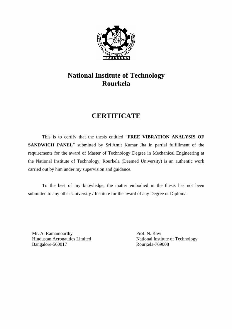
Fig 1.3 Typical sandwich constructions
A useful classification of sandwich composites according to their core properties by
respective direction is shown in fig.1.3. To see the core effect upon sandwich strength, let us
consider the honeycomb-core and the truss-core sandwich composite.
The honeycomb sandwich has a ratio of shear rigidities in the xz and yz planes of
approximately 2.5 to 1. The face sheets carry in-plane compressive and tensile loads, whereas
the core stabilizes the sheets and builds up the sandwich section.
The truss-core sandwich has a shear rigidity ratio of approximately 20 to 1. It can carry
axial loads in the direction of the core orientation as well as perform its primary function of
stabilizing the face sheets and building up the sandwich section [5].
5

1.3 PROPERTIES OF MATERIALS USED IN SANDWICH COSNTRUCTION
No single known material or construction can meet all the performance requirements of
modern structures. Selection of the optimum structural type and material requires systematic
evaluation of several possibilities. The primary objective often is to select the most efficient
material and configuration for minimum-weight design [5].
Face Materials
Almost any structural material which is available in the form of thin sheet may be
used to form the faces of a sandwich panel. Panels for high-efficiency aircraft structures
utilize steel, aluminium or other metals, although reinforced plastics are sometimes adopted
in special circumstances. In any efficient sandwich the faces act principally in direct tension
and compression. It is therefore appropriate to determine the modulus of elasticity, ultimate
strength and yield or proof stress of the face material in a simple tension test. When the
material is thick and it is to be used with a weak core it may be desirable to determine its
flexural rigidity [4].
Core Materials
A core material is required to perform two essential tasks; it must keep the faces the
correct distance apart and it must not allow one face to slide over the other. It must be of low
density. Most of the cores have densities in the range 7 to 9.5 lb/ft3.
Balsa wood is one of the original core materials. It is usually used with the grain
perpendicular to the faces of the sandwich. The density is rather variable but the transverse
strength and stiffness are good and the shear stiffness moderate.
Modern expanded plastics are approximately isotropic and their strengths and
stiffnesses are very roughly proportional to density.
In case of aluminium honeycomb core, all the properties increase progressively with
increases in thickness of the foil from which the honeycomb is made [4].
1.4 CURRENT APPLICATIONS
Aerospace Field
In Aerospace industry various structural designs are accomplished to fulfill the
required mission of the aircraft. Since a continually growing list of sandwich applications in
aircraft/helicopter (example-Jaguar, Light Combat Aircraft, Advanced Light Helicopter)
includes fuselages, wings, ailerons, floor panels and storage and pressure tanks as shown in
6

Fig 1.4(a) Application of sandwich structure in aircraft [18].
\
Fig 1.4(b) Application of sandwich structure in helicopter [17].
(1. Rotor Blades, 2. Main and Cargo Doors, 3. Fuselage Panels, 4. Fuselage, 5. Boom and
Tail section)
fig (1.4). Honeycomb sandwich structures have been widely used for load-bearing purposes
in the aerospace due to their lightweight, high specific bending stiffness and strength under
distributed loads in addition to their good energy-absorbing capacity [8]. In a new space-
formed system called "Sunflower," the reflector is of honeycomb construction, having a thin
coating of pure aluminum protected by a thin coating of silicon oxide to give the very high
reflectivity needed for solar-energy collection. Thirty panels fold together into a nose-cone
package in the launch vehicle.
7

Building Construction
Architects use sandwich construction made of a variety of materials for walls,
ceilings, floor panels, and roofing. Cores for building materials include urethane foam (slab
or foam-in-place), polystyrene foam (board or mold), phenolic foam, phenolic-impregnated
paper honeycomb, woven fabrics (glass, nylon, silk, metal, etc.), balsa wood, plywood, metal
honeycomb, aluminum and ethylene copolymer foam. Facing sheets can be made from rigid
vinyl sheeting (fiat or corrugated) ; glass-reinforced, acrylic-modified polyester; acrylic
sheeting; plywood; hardwood; sheet metal (aluminum or steel); glass reinforced epoxy;
decorative laminate; gypsum; asbestos; and poured concrete [5].
Damped Structures
An increasing number of vibration problems must be controlled by damping resonant
response. By using a symmetric sandwich panel with a viscoelastic core, various degrees of
damping can be achieved, depending on the core material properties, core thickness, and
wavelength of the vibration mode [5].
8

Chapter 2
LITERATURE SURVEY
9

LITERATURE SURVEY
2.1 TRUSS CORE SANDWICH
Sandwich panels are thin-walled structures fabricated from two flat sheets, separated by
and attached to a core. An analytical solution for the dynamic response of such structures is
not available but equivalency in the form of a homogenous orthotropic thick plate can be
formulated. This paper considers a truss-core sandwich panel that is similar to conventional
sandwich systems, but eliminates many of the attendant problems associated with fabrication
of conventional forms. The dynamic response of the truss-core sandwich panel is then
formulated as a homogeneous orthotropic thick plate. Closed-form solution for a clamped
plate is derived. Closed-form solutions are compared with both 2-D and 3-D finite element
results. According to T.S. LOK and Q.H. CHENG, corrugated form has many advantages
over other form of sandwich structure. Some advantages are
• The elimination of discrete connections and all its attendant problems. This is crucial
for structures or vessels designed to maintain pressure and water-tightness between
the outer and inner environments.
• Better material utilization and ease of manufacturing since only one extrusion process
is needed. Transportation, handling and construction cost would be reduced since no
large flexible thin sheets are involved.
• Promotion of designer flair to create curved shapes that linear flat conventional
sandwich panels are unable to provide [1].
2.2 OPTIMIZATION OF SANDWICH MATERIAL
This article presents an approach to facilitate comparison and optimization of
sandwich material combinations. Equivalent homogenized sandwich material properties
(bending stiffness, density, and cost) are presented graphically in material selection charts to
enable an efficient performance per cost evaluation. The effects of core shear deformations
and panel production costs can be included in those sandwich material selection charts. In
addition to weight advantages, economical advantages are vital for the potential use of
sandwich construction in many applications.
According to JOCHEN PFLUG AND IGNAAS VERPOEST, Sandwich
construction with a low cost core material can not only be lightweight but also cost effective,
especially since the advancement and automation of production processes enable a reduction
10

in production cost for lightweight sandwich panels. However, for low cost applications,
sandwich construction is frequently not considered because of limited knowledge about their
cost-saving potential. It is thus important to provide tools to evaluate and present the cost-
saving potential of sandwich material combinations already in the stage of materials
selection. For a given sandwich material combination, an optimization, including shear
deformations of the core as well as optimizations toward a maximum bending strength,
involving different failure modes, can be performed [6].
2.3 GLOBAL HIGHER THEORY
Laminated composite and sandwich plates are being increasingly used in advanced
aerospace structures because they can exhibit many favorable characteristics such as high
specific modulus and strength and low specific density. To use them efficiently, it is
necessary to develop appropriate models capable of accurately predicting their structural and
dynamical behavior.
Due to ignoring the transverse shear deformation and overestimating the natural
frequency, the classical laminate plate theory becomes inadequate for the analysis of thick
laminated and sandwich plates. Therefore it is necessary to consider the effect of transverse
shear deformation in the study of thick laminated structures. To take into account the effects
of shear deformation, the first-order shear deformation theories are firstly developed whereas
the accuracy of solutions of this theory will be strongly dependent on the shear correction
factors. In order to overcome the limitations of first-order shear deformation theory, the
global higher-order theories that include higher-order terms in Taylor’s expansions of the
displacement in the thickness direction. However, by further research, it is found that the
global higher-order theories also overestimate natural frequency for laminated composite
plates with different thickness and materials at each ply and soft-core sandwich plates
because these higher-order theories violate continuity conditions of the transverse stress
components.
To overcome the limitations of the global higher-order theories and layerwise
theories, this paper is to use the global–local theory to predict dynamical response of
laminated composite plates with arbitrary layout and soft-core sandwich plates. The global–
local higher-order theory is firstly developed by Li and Liu and further study on the global–
local theory has been presented by Wu and Chen. This theory possesses the accuracy of
layer wise theory and efficiency of global higher-order theory, moreover, which satisfies
displacements and transverse shear stresses continuity conditions at the interfaces.
11

Natural frequencies of laminated composite and sandwich plates have been calculated
by using the global–local higher-order theory, and these results are compared with those
previously published. These comparisons revealed that the present theory can accurately
predict natural frequencies of general laminated plates. Moreover, this theory is still suitable
for dynamical problems of laminated composite plates with variational thickness and
materials at each layer and soft-core sandwich plates. However, numerical results show that
for these special structures, the global higher- and first-order theories that violate continuity
of interlaminar stresses will encounter some difficulties and overestimate the natural
frequencies [7].
12

Chapter 3
FINITE ELEMENT FORMULATION
13

FINITE ELEMENT FORMULATION 3.1 THEORY
The solution of a real life problem involving an arbitrary plate geometry and
complicated loading and boundary conditions cannot be easily realized using analytical
methods. A numerical analysis technique, especially finite element analysis method, is suited
most to solve such problems.
The finite element method is essentially a piecewise application of a variational
method. The finite element formulation is based on the conventional Rayleigh-Ritz method
and Galerkin Method. In the Rayleigh-Ritz method we construct a functional that expresses
the total potential energy π of the system in terms of nodal variables di. The problem is solved
using the stationary-functional conditions ∂π/∂di =0 [9].
In the case of the Galerkin method, the functional for the residual R is formed using
differential equations of the residual R to zero. In structural mechanics, both the Rayleigh-
Ritz method and the Galerkin method yield identical results, when both use the same field
variables.
The Classical Plate Theory evaluates the behavior of the thin isotropic plate, assuming
that the normal to the undeformed middle plane remains straight, normal and inextensible
during the deformation [14]. But same assumption is not valid for a laminated sandwich plate
as the transverse shear deformation and elastic coupling effects become more predominant
and deformation of the core plays a vital role in overall deformation of the plate. Analysis of
a sandwich plate calls for inclusion of the shear deformation by splitting the total deflection
into deflection due to bending and due to shear deformation of the core. The improvement in
the classical plate theory due to Mindlin and Reissner, takes into account the effects of shear
deformation, in addition an arbitrary shear correction factor to the transverse shear stiffness is
also applied in order to account for the non uniform shear distribution at any cross section.
3.2 SHEAR DEFORMATION OF THE PLATE
The theory proposed by Mindlin assumes that straight lines originally normal to the
mid surface, before the deformation , remains straight but not normal to the deformed mid
surface i.e. the average rotation of the section may be taken as the rotation in which normal
remains perpendicular to the mid surface plus an additional rotation due to transverse shear.
Thus the actual shear deformation is assumed to be equivalent to a straight line representing a
uniform shear strain through the thickness [12]. This theory makes following assumptions:-
14

(a) The lateral deflections ‘w’ are small.
(b) Normal to the plate mid surface before deformation remains straight but not
necessary normal to it after deformation.
(c) Stresses normal to the mid surface are negligible
In this theory, the second assumption differs from the Classical Plate Theory, while other two
are same for both the theories. Fig 3.1(a) in which Φx, denotes an average transverse shear
strain for a section y = constant, the total rotation θx, can be express as follows:-
where dw/dx is the rotation of the element along the center line due to bending only.
Similarly for the section x = constant (fig 2.1(b))
Hence the average shear strain Φx and Φy are given by following relations:-
15

16

The kinematics relation can be expressed as
where { k } are the plate curvatures,{ θ } are the planar relations,{ γ } are the shear strain and ‘w’ are the lateral deflections of the plate. The bending and shear behavior of an anisotropic plate are given by [11]: -
where CS shear correction factor. It is a function of cross sectional shape and Poisson’s ratio
(ν).
The bending and shear strain energies are expressed as follows:-
where
17

3.3 CONSTITUTIVE EQUATION FOR ANISOTROPIC PLATES
Consider a unidirectional lamina as depicted in the fig. 3.2. Neglecting the normal stresses
perpendicular to the plane of the lamina, the stress-strain relations in the principal material
direction 1, 2 and 3 are as follows [11]:-
18

where
The stress-strain relations of the lamina with respect to the x, y and z axes are as
follows:-
3.4 CONSTITUTIVE RELATIONS FOR THE LAMINATED PLATE
Consider a laminated plate having width w and thickness h. The plate is made of n number of
laminae. The interface between the lamina is very thin and they do not deform under shear.
Thus the displacements are continuous through the thickness of the laminate. The linear plain
strains at a distance z from the mid surfaces are given as follows [10]:-
19

The internal force and moment resultants of the laminate are obtained by integrating
elemental forces and moments over the thickness of the laminate.
Equations (3.15) through (3.17) can be represented as follows:-
20
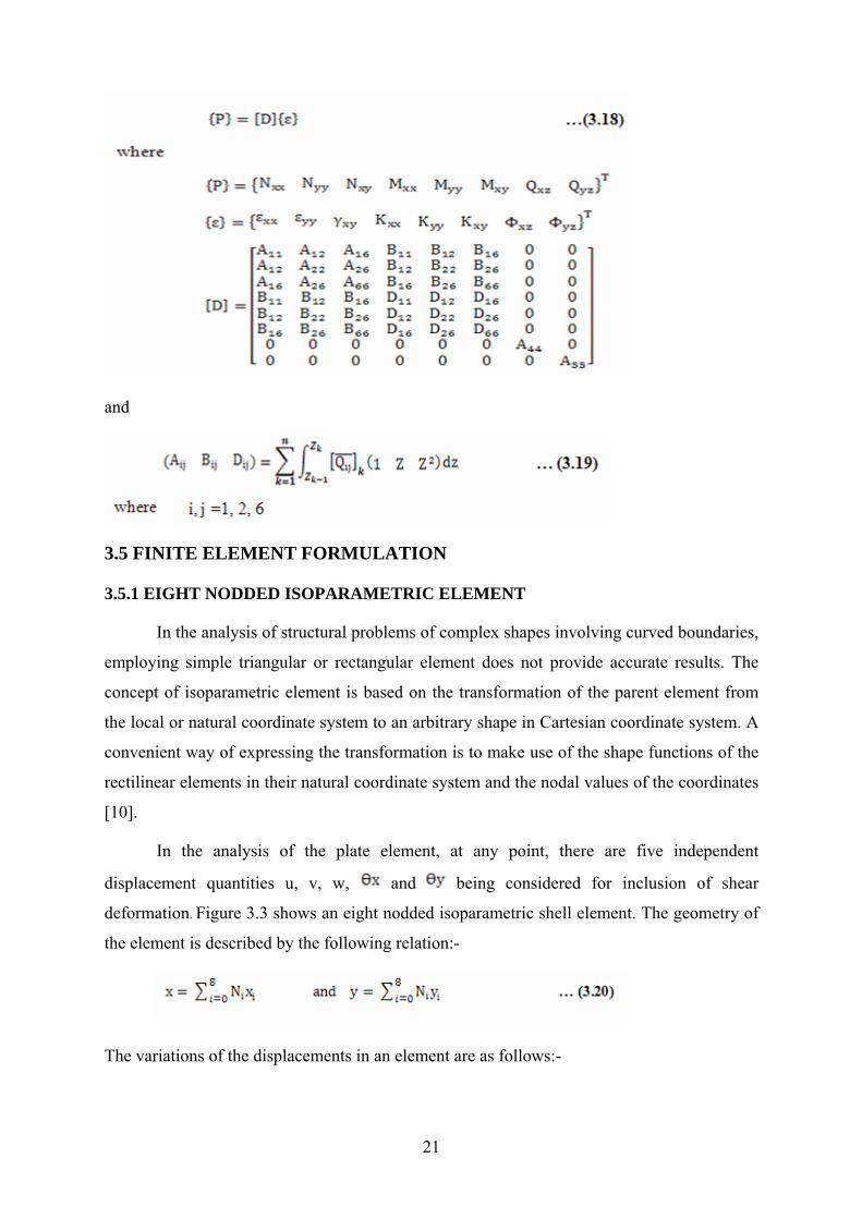
and
3.5 FINITE ELEMENT FORMULATION
3.5.1 EIGHT NODDED ISOPARAMETRIC ELEMENT
In the analysis of structural problems of complex shapes involving curved boundaries,
employing simple triangular or rectangular element does not provide accurate results. The
concept of isoparametric element is based on the transformation of the parent element from
the local or natural coordinate system to an arbitrary shape in Cartesian coordinate system. A
convenient way of expressing the transformation is to make use of the shape functions of the
rectilinear elements in their natural coordinate system and the nodal values of the coordinates
[10].
In the analysis of the plate element, at any point, there are five independent
displacement quantities u, v, w, and being considered for inclusion of shear
deformation. Figure 3.3 shows an eight nodded isoparametric shell element. The geometry of
the element is described by the following relation:-
The variations of the displacements in an element are as follows:-
21

where Ni are the shape functions, xi and yi are the nodal coordinates, (ui, vi and wi) are the
nodal displacements along x, y, z directions, and are the nodal slopes along x, y
directions.
The shape functions are as follows:-
3.5.2 DISPLACEMENT ANALYSIS
The displacements {u} within an element are usually expressed as [9]
where [N] is shape function and {d} is the element nodal displacements with respect to the
local axis. The strains {ε} in an element are defined in terms of the displacements as
where [∆] is differential operator.
Strain-nodal displacement relations are obtained by combining equations (3.23) and (3.24):-
22

Stress-strain relation in an element is expressed as
where [Q] is the elastic stiffness.
Hence the stress-nodal displacement relations are obtained as
The total potential of an element is first computed to apply the Rayleigh-Ritz variational
approach. The total potential of the element is given by
where {q} are the surface tractions.
From above equations, we get
Applying the principle of Minimum Potential Energy yields
where [Ke ] is element stiffness matrix and {Pe } are the element nodal forces. These
are expressed as
Transformation of eq. (3.31) from the local axes to the global axes and proper assembly of
terms over all elements will lead to a set of equilibrium equations for the complete structure,
as
where [K], {d} and {P} correspond to the global axes.
According to Galerkin weighted residual approach, the residual equation is expressed
23

as
where are equilibrium equations and [N] are the weight functions.
Applying the Green-Gauss’s Theorem to eq. (3.34) and expanding-
After eliminating the non-essential boundary conditions, eq. (3.35) can be written in
the form as given by eq. (3.33).
3.6 VIBRATION SOLUTION TECHNIQUE
Using isoparametric finite element concept, strain nodal displacement relations for the
element (in matrix form) is expressed as
The element stiffness matrix is given by
where [B] is the strain displacement matrix given in eq. (3.36) and [D] is the constitutive
matrix given in eq. (3.18). The total element stiffness matrix [Ke] is the sum of bending
stiffness matrix [Kb] and transverse shear stiffness matrix [Ks].
The element mass matrix is expressed as
24

with
Here ρ is mass density.
The stiffness matrix [Ke] and the mass matrix [Me] are evaluated first by expressing the
integrals in the local isoparametric coordinates and of the element and then performing
numerical integration employing the 2x2 Gauss Quadrature .The element matrices are
assembled after performing appropriate transformations. Thus one obtains for the static case
and for free vibration case
where is frequency of the laminated plate.
25

Chapter 4
MACROMECHANICAL BEHAVIOUR OF
LAMINATES
26

MACROMECHANICAL BEHAVIOUR OF LAMINATES 4.1 INTRODUCTION
The main constituents of a structural composite are the reinforcements and the
reinforcements and the matrix. The reinforcements, which are stronger and stiffer, are
dispersed in a comparatively less strong and stiff matrix material. The reinforcements share
the major load and in some cases especially when a composite consists of fiber
reinforcements dispersed in a weak matrix (e.g.-carbon/epoxy composite), the fibers carry
almost all the load. The strength and stiffness properties of are therefore controlled by
strength and stiffness of constituent fibers. The matrix also shares the load when there is not
much difference between the strength and stiffness properties of reinforcements and matrix
(e.g.-SiC/Titanium composite). For example to obtain a good conducting composite with SiC
fibers, aluminum matrix is a better option due to high thermal conductivity than titanium
matrix [11].
4.2 MACROMECHANICAL BEHAVIOR
4.2.1 INTRODUCTION
The heterogeneity in a composite material is introduced due to not only its bi-phase or
multi-phase composition, but also laminations. This leads to a distinctly different stress strain
behavior in the case of laminates. The anisotropy caused due to fiber orientations and the
resulting extension-shear and bending-twisting coupling as well as the extension-bending
coupling developed due to unsymmetric lamination adds to the complexities [13].
4.2.2 UNIDIRECTIONAL LAMINA
The stress-strain relations for a unidirectional lamina with two-dimensional
anisotropy (fig 4.1(a)-off-axis lamina), are expressed as
where are the reduced stiffnesses (elastic constants) for plane stress.
27

Similarly, in terms of compliances, the stress strain relations are
For the case of an on-axis lamina with two-dimensional orthotropy (fig 4.1), the stress-strain
relations are
where
28

In the above equations, the engineering constants ( ) are referred
to the orthotropic axis system ( ) [11].
4.2.3 TRANSFORMATION OF ELASTIC CONSTANTS
If the elastic constants and compliances of a material are known with respect to a given co-
ordinate system, then the corresponding values with respect to any other mutually
perpendicular coordinate can be determined using transformation rules[13].
Two dimensional cases
If the elements of and refer to the ( ) and ( ) coordinates
respectively, then transformation laws for reduced elastic constants are obtained as follows
[11]:
where and are defined as
29

From equation (4.11) and (4.13):
4.2.4 GENERAL LAMINATES
Let us consider a general thin laminate of thickness h (fig. 4.2). The laminate consists
of n number of unidirectional and/or bidirectional laminae, where each lamina may be of
different materials and thicknesses and have different fibre orientations (Φ). A thin general
laminate is essentially a two-dimensional problem, but cannot be treated as a two-
dimensional plane stress problem as has been done for a unidirectional lamina. The existence
of extension-bending coupling causes bending, even if the laminate is subjected to inplane
loads only. Therefore, thin plate bending theories are employed in derivation of constitutive
relations. Kirchhoff’s assumptions related to the thin plate bending theory
are applicable for constitutive relations [13].
30

Let u10, u2
0 and w are the mid-plane displacements, and w is constant through the
thickness of the lamina. Then the mid-plane strains are given by
and the curvatures, which are constant through the thickness of the laminate, are
expressed as
The strains at any distance z are then given as
Now from eq. 4.1, for distance z
31

The stress and moment resultants (fig. 4.3) are evaluated per unit length of the laminate as
follows:
Thus,
32

All stress and moment resultants can also be expressed as
Equation 4.23 represents the constitutive relations for a general laminate, and Aij, Bij,
and Dij are the inplane, extension bending coupling and bending stiffnesses, respectively. All
these stiffnesses are derived for a unit length of the laminate. The elastic properties of each
lamina are generally assumed to be constant through its thickness, as these laminae are
considered to be thin. Then Aij, Bij, and Dij are approximated as
Several types of mechanical coupling in a general laminate are shown in eq.
4.23.These are grouped together as follows:
33

Chapter 5
BENDING AND VIBRATION OF LAMINATED PLATES
34

BENDING AND VIBRATION OF LAMINATED PLATES 5.1 INTRODUCTION
The formulae presented in this chapter are based on the classical bending theory of thin composite plates. The small deflection bending theory for a thin laminate composite plate is developed based on Bernoulli's assumptions for bending of an isotropic thin plate. The development of the classical bending theory for a thin laminated composite plate follows Kirchhoff's assumptions for the bending of an isotropic plate. Kirchhoff's main suppositions are as follows [13]:
• The material behavior is linear and elastic. • The plate is initially flat. • The thickness of the plate is small compared to other dimensions.
• The translational displacements ( and w) are small compared to the plate
thickness, and the rotational displacements ( ) are very small compared to unity.
02
01 ,uu
0 01,1 2,2andu u
• The normals to the undeformed middle plane are assumed to remain straight, normal
and inextensional during the deformation so that transverse normal and shear strains
are neglected in deriving the plate kinematic relations.
5.2 THIN LAMINATED PLATE THEORY
Consider, a rectangular, thin laminated composite plate of length a, width b and
thickness h as shown in fig.5.1. The plate consists of a laminate having n number of laminae
with different materials, fibre orientations and thicknesses. The plate is subjected to surface
loads q's and m's per unit area of the plate as well as edge loads per unit
length. Let us consider and w are mid-plane displacement components. It is assumed
that Kirchhoff's assumptions for the small deflection bending theory of a thin plate are valid
in the present case. One of these assumptions is related to transverse strains
02
01 ,uu
which are neglected in derivation of plate kinematic
relations i.e., stress-strain relations [13].
35

36

Considering the dynamic equilibrium of an infinitesimally small element dx1 dx2 (fig. 5.2), the following equations of motion are obtained
where commas are used to denote partial differentiation. Combining equations (5.3) through (5.5), we obtain
Substituting equation (4.23) in equations (5.1), (5.2) and (5.6) and noting equations (4.16) and (4.17), we obtain the following governing differential equations in terms of mid-
plane displacements and w. 02
01 ,uu
37

Consider effect of transverse load q only on the laminates. Equations (5.7) to (5.9) reduce to
Symmetric laminates:
For symmetric laminated plates, the extension-bending coupling matrix [B] = 0 and the above equations simplify to
5.3 FREE VIBRATION OF LAMINATED PLATE
5.3.1 UNSYMMETRICAL CROSS-PLY LAMINATED PLATE
For cross ply laminates, the material directions are oriented at 0 or 90 degrees.
For the stacking sequence [0/90] n of the laminate
A16 = A 26 = B 12 = B16 = B 26=B66 =D16 = D26 = 0
A11 = A 22, B 22 = -B11, D22 = D11
The static case of equations (5.13) to (5.15) for the present case are expressed as
38

The equation of motion is expressed as
where ρ is the average density of laminate.
In the above equations, the transverse inertia is only included and the in plane inertia forces are neglected [15].
Boundary conditions for simply supported laminated plate
In the equation (5.21), transverse inertia is only included.
Solution of the above equations (5.19), (5.20) and (5.21) which satisfy the boundary conditions given in the equation (5.22) is written as [15]
Substituting (5.23) into above equations (5.19), (5.20) and (5.21) yield the following
homogeneous algebraic equations
where
39

where k is aspect ratio. a and b are plate dimensions in x1 and x2 directions.
In order to obtain a nontrivial solution to (5.24) the determinant of the coefficient matrix must vanish. Thus
Expanding the determinant in the above equation (5.25), the circular frequency is obtained.
where
5.3.2 SIMPLY SUPPORTED SYMMETRICAL CROSS-PLY LAMINATED PLATE
For symmetric laminated plates, [B] = 0. The circular frequency is expressed as
40
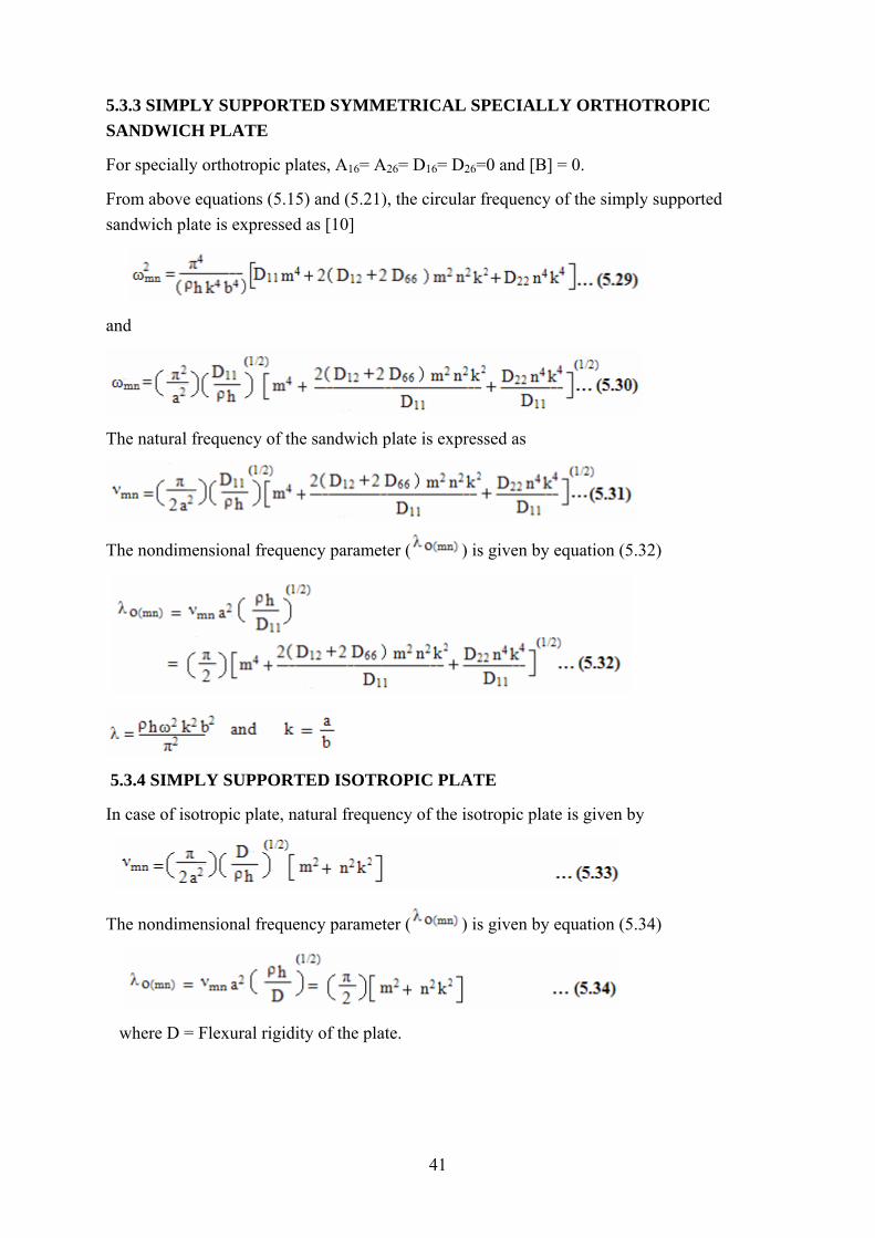
5.3.3 SIMPLY SUPPORTED SYMMETRICAL SPECIALLY ORTHOTROPIC SANDWICH PLATE
For specially orthotropic plates, A16= A26= D16= D26=0 and [B] = 0.
From above equations (5.15) and (5.21), the circular frequency of the simply supported sandwich plate is expressed as [10]
and
The natural frequency of the sandwich plate is expressed as
The nondimensional frequency parameter ( ) is given by equation (5.32)
5.3.4 SIMPLY SUPPORTED ISOTROPIC PLATE
In case of isotropic plate, natural frequency of the isotropic plate is given by
The nondimensional frequency parameter ( ) is given by equation (5.34)
where D = Flexural rigidity of the plate.
41

Chapter 6
SANDWICH STRUCTURE
42

SANDWICH STRUCTURE 6.1 SANDWICH PRINCIPLE
The basic prerequisite for high-performance structural component parts as used in
aerospace applications is light-weight design wherever possible. An essential component of
these light-weight structures is load-bearing and buckling optimized shell elements. The
classical method to obtain improved buckling properties is using sandwich structures have
also proven their worth in a number of fields. The performance of a sandwich structure
depends primarily upon the efficiency of surface skins and the distance between them. A
great distance between the surface skins produces a correspondingly great geometrical
moment of inertia, thus leading to high bending stiffness. Since this arrangement subjects the
core of the sandwich to a relatively small amount of stress, it can be reduced in weight
significantly. Extremely thin-walled sandwich structures present the problem of how force is
introduced and the sandwich structure's sensitivity towards impact loads. This means that a
minimum wall thickness is required for the surface skins to be able to ensure that it is
adequate to the purpose.
6.1.1 FACE SHEETS Aluminium honeycomb core The face sheets provide the flexural rigidity of the sandwich structure. It should also possess
tensile and compressive strength.
6.1.2 CORES The purpose of the core is to increase the flexural stiffness of the panel. The core in general
has low density in order to add as little as possible to the total weight of the sandwich
construction. The core must be stiff enough in shear and perpendicular to the faces to ensure
that face sheets are distant apart. In addition the core must withstand compressive loads
without failure.
43

6.1.2.1 ALUMINUM HONEYCOMB These cores are available in variety of materials for sandwich structures. These cores can be
formed to any shape or curve without excessive heating or mechanical force. Honeycombs
have very high stiffness perpendicular to the faces and the highest shear stiffness and strength
to weight ratios of the available core materials. The most commonly used honeycombs are
made of aluminum or impregnated glass or aramid fiber mats such as nomex and
thermoplastic honeycombs.
6.2 STIFFNESS TO WEIGHT RATIO OF SANDWICH PLATE
Let us consider a stiffened single skin structure and sandwich structure as shown in figure
6.3. Three cases are considered for stiffness to weight ratio analysis.
Face thickness= t and Mass of Face =25xMass of Core
.From Case III discussion, for a face/core thickness ratio =1/10, which gives a relative
bending stiffness 75.8 times the stiffness of the equivalent single skin. Hence, sandwich is a
structurally efficient structure with regard to stiffness/ weight ratio.
44

Chapter 7
RESULTS AND DISCUSSIONS OF ISOTROPIC PLATE
45

RESULTS AND DISCUSSIONS OF ISOTROPIC PLATE 7.1 EXPERIMENTAL RESULTS
In the present investigation, frequencies of vibration of rectangular plate with various support
boundary conditions are studied by means of experiments. The results obtained using
experiments are compared with Finite Element package (ANSYS) and theoretical
calculations.
An isotropic Aluminium plate is of dimensions (49.5 cm x 36.1 cm) when measured
by a meter scale and the average thickness was 2.75 mm when measured by micrometer
screw gauge.
Table 7.1 Properties for Aluminium
Serial Number Property Value
1 Young’s Modulus 70GPa
2 Poisson’s Ratio 0.33
3 Density 2700 kg/m3
The Test facility
The Test facility used to find the frequencies of vibration is shown in the fig (7.1). The setup
consists mainly of three subsystems
i) The Loading System
ii) The Excitation System
iii) The Measuring System
The loading frame consists of two vertical steel I beams with two cross members, one
at the top and the other at some height from the ground. The loading system facilitated the
holding of the specimen and provided the necessary boundary conditions. The excitation
system consisted of an oscillator, a power amplifier and an electro-dynamic shaker. A
sinusoidal electrical signal was generated by the oscillator. The output of the oscillator was
fed to the shaker through the power amplifier. The shaker was kept in alignment with the
loading system and the shaker head was fastened to the threaded stud attached to the
specimen by means of a coupling nut. The excitation system facilitated the application of a
sinusoidal dynamic load of the desired amplitude and frequency. The amplitude of the forced
46

oscillation was measured in terms of the shaker current indicated by an output ammeter on
Fig 7.1 Schematic diagram for vibration experiment
Note: - Frequency means transverse vibration natural frequency
the power amplifier. A piezoelectric accelerometer was been stuck at a suitable location on
the plate to pick up the plate response.
The Instrumentation:
The table gives information about the various instruments used for the experiment.
The Experimental Procedure
Every instrument used in the experiment was calibrated and adjusted. Then the
experimental setup was organized as shown in the figures (7.1) and (7.2). The plate was
attached to the loading system using the screw-jack mechanism and the adjusting screw. The
threaded stud attached to the plate was then fastened to the shaker head by means of a
coupling nut. During all these initial adjustments, the shaker was kept in standby mode. Also
the amplitude knobs on the oscillator and on the power amplifier were kept at zero position.
The control was then switched to the operate position. The amplitude knob on the amplifier
was turned and kept at a certain finite amplitude level. The desired amplitude level was
obtained by adjusting the amplitude knob on the oscillator.
Then the frequency of excitation was slowly increased from a minimum value of 5 hertz. The
response of the plate was constantly monitored on the vibration meter and the FFT analyzer.
47

As the frequency was increased, the response of the plate also increased and the
frequency was kept constant when the plate was vibrating with the largest amplitude. This
was the first significant resonance behavior and it corresponded to the first fundamental
frequency was kept constant when the plate was vibrating with the largest amplitude.
This was the first significant resonance behavior and it corresponded to the first fundamental
frequency, i.e. the first mode of vibration. The frequency of the plate was then equal to the
excitation frequency. This is a characteristic resonance. As the frequency was further
increase, again large amplitude plate vibrations were observed. This corresponded to the
second mode of resonance. The corresponding excitation frequency was recorded. The
procedure was repeated for further values of resonant frequencies corresponding to higher
modes.
48

Results for different boundary conditions
Table 7.3 Experimental results for clamped and simply supported
Experiment
Mode All Sides Clamped All Sides Simply Supported
1
2 240 154
3 373 229
4 414 287
5 449 302
7.2 FINITE ELEMENT PACKAGE (ANSYS) RESULTS
The modal analysis of isotropic plate is performed using the Finite Element Package
(ANSYS). The inputs are considered as given in table 7.1. 792 elements are used for the
present analysis. The mode shapes, deflections and frequencies are given below. SHELL 99
element is used for this analysis.
7.2.1 CLAMPED PLATE
Meshed model First Mode
49

Second Mode Third Mode
Fourth Mode Fifth Mode
Fig7.2 Mode shapes for clamped plate
7.2.2 SIMPLY SUPPORTED PLATE
First Mode
50

Fourth Mode Fifth Mode
Fig 7.3 Mode shapes for simply supported plate
7.3 COMPARISON OF EXPERIMENTAL WORK AND FEA WORK WITH
ANALYTICAL SOLUTION
The results of experimental, FEA and analytical work are comparable.
Table 7.4 Comparison of frequency (Hz) results of isotropic plate
** Errors are calculated by comparison of FEA (ANSYS) and experimental results.
51

Variation of frequency values in the analysis in comparison is due to consideration of
assumptions (setup assumption).
Note:-S-Simply Supported and C- Clamped (Fixed)
7.4 EFFECT OF ASPECT RATIO ON NON-DIMENSIONAL FREQUENCY
OF ISOTROPIC PLATE
Keeping all other parameters constant, the effect of aspect ratio on the natural
frequency is analyzed. The nondimensional frequency parameter is given by equation (5.34)
for simply support condition. The table below gives the natural frequencies of the aluminum
plate for different values of aspect ratios. It also shows the associated mode shapes in
brackets as (m, n).
52

7.5 EFFECT OF CHANGE OF DIMENSION ON FREQUENCY (MASS
CONSTANT) OF ISOTROPIC PLATE
The effect of change in dimension (width and thickness) of plate on the natural frequency is
analyzed as
Three cases are studied and results depend upon increment and decrement of width
and thickness. 625 elements are used for the effect of dimension change on natural frequency.
For the following cases the results are given in the table 7.3.
53

Chapter 8
RESULTS AND DISCUSSIONS OF SANDWICH PANAL
54

RESULTS AND DISCUSSIONS OF SANDWICH PANAL In this analysis the specimen is tested for simply supported condition and the results
are generated which are compared with different methods. Material properties of honeycomb
sandwich panel having aluminium face sheets are
8.1 EXPERIMENTAL RESULTS
In the present investigation, frequencies of vibration of sandwich panel with simple
support condition are studied by means of experiment. The model is shown in fig 8.1.The
results obtained using experiments are compared with Finite Element Package (ANSYS) and
theoretical calculations. The table 8.1 gives information about the various instruments used
for the experiment.
Fig 8.1 Three layered simply supported sandwich panel
The experimental procedure of vibration experiment is same as for the isotropic plate.
The procedure is repeated for further values of resonant frequencies corresponding to higher
modes. The experimental results are given in the 8.3 section.
55

8.2 FINITE ELEMENT PACKAGE (ANSYS) RESULTS
8.2.1 MODAL ANALYSIS
The modal analysis of sandwich panel is performed using the Finite Element Package
(ANSYS). The inputs are considered as given in the experimental work. SHELL 99
(quadratic element) is used for the vibration analysis. 759 elements and 2390 nodes are used
for accurate analysis. The mode shapes, deflections and frequencies are given below.
Fig 8.2 Meshed sandwich panel
56

Fig 8.3 Mode shapes of simply supported sandwich panel
57

Fig 8.4 Deflection vs. frequency graph at nodes 1877 and 1333
8.2.2 CONVERGENCE STUDY
The results for different discretization of the simply supported sandwich plate are
presented in Table 8.2. ANSYS uses 1x1, 2x2, 3x3 and 4x4 mesh sizes and corresponding
elements 1218, 759, 532 and 294 for convergence study. The uniformly converging results
assure the accuracy and correctness of the present analysis.
Note:- Frequency means transverse vibration natural frequency
8.3 COMPARISON OF FEA (ANSYS) WITH ANALYTICAL SOLUTION,
EXPERIMENTAL WORK AND FEA (MSC/NASTRAN)
The results of the experiment presented in table 8.3 are good agreement with FEA and
analytical analysis. Error calculated on the basis of comparison between results of FEA
(ANSYS) and experimental values. The difference of results between these analyses is due to
difference between modeling of sandwich panel and consideration of assumptions of material
properties and setup arrangements.
58

Table 8.3 Comparison of experimental results with FEA (ANSYS) results, analytical results
and FEA (MSC/NASTRAN)
Frequency
Mode Number
Experimental Results(Hz)
FEA (ANSYS)
Analytical FEA Error** Results(Hz) (MSC/NASTRAN)
Results(Hz) Results(Hz) (%)
1 21.670 24.280 25.079 2 44 43.315 48.248 51.396 +1.56 3 67 64.991 69.781 72.435 +3.08 4 78 79.370 82.454 81.974 -1.72 5 89 86.616 93.312 91.001 +2.75
** Error is calculated on the basis of comparison between FEA (ANSYS) and Experimental Results Note: - Frequency means natural frequency of transverse vibration
8.4 STUDY OF COMPARISON BETWEEN SANDWICH PLATE AND
EQUIVALENT PLATE
Comparison of modal analysis between simply supported sandwich plate and same
dimensions aluminium face plate is shown in the table 8.4. Mesh sizes for present study are
1x1 and 2x2. Figure 8.3 shows that sandwich plate having 1.4 times higher fundamental
frequency than equivalent plate. Increase in frequency is due increase in flexural stiffness of
the plate.
59

Fig 8.5 Variation of frequency between sandwich panel and equivalent panel
8.5 PARAMETER STUDIES USING FE MODEL
FE model (fig 8.2) is used to investigate the effects of various design parameters on
the frequencies of free vibration of simply supported honeycomb sandwich plate.
8.5.1 EFFECT OF INCREASE IN THICKNESS OF THE CORE ON FREQUENCIES
OF VIBRATION OF SANDWICH PLATE
1x1 and 2x2 meshing are considered for present study. Considering other parameters
constant, increase in core thickness increases natural frequency of the sandwich plate. Table
8.5 shows the natural frequencies at different core thickness. Figure 8.4 shows the effect of
increase of the core thickness on the natural frequency considering 1x1 mesh size. Difference
of the natural frequency is more at higher mode with respect to first mode.
60

Fig 8.6 Effect of increase of core thickness on frequencies of sandwich panel
8.5.2 EFFECT OF INCREASE IN THICKNESS OF THE FACE SHEETS ON
FREQUENCIES OF VIBRATION OF SANDWICH PLATE
1x1 and 2x2 meshing are considered for present study. Considering other parameters
constant, increase in face sheets thickness increases natural frequency of the sandwich plate.
Table 8.6 shows the natural frequencies at different core thickness. Figure 8.5 shows the
effect of increase of the face sheets thickness on the natural frequency considering mesh size
1x1. Difference of the natural frequency is more at higher mode with respect to first mode.
Table 8.6 Frequencies for different face sheets thickness of sandwich panel
61

Fig 8.7 Effect of increase of face sheets thickness on frequencies of sandwich panel
8.5.3 THE EFFECT OF INCREASE OF DENSITY OF THE CORE ON THE
NATURAL FREQUENCY OF SANDWICH PLATE
Study of variation of natural frequencies due to increase of density of core of simply
supported sandwich plate are analyzed by FEA (ANSYS).Table 8.7 shows the different
modes of natural frequencies for different densities of the core [16]. Figure 8.6 shows the
graph between natural frequencies and densities of the core. Considering other parameters
constant, increase in density of the core decreases natural frequency of the sandwich plate.
Increase in density is more effective for higher modes of vibration of simply supported
sandwich panel.
62

Fig 8.8 Effect of increase of density on natural frequencies of sandwich panel
8.5.4 EFFECT ON THE SANDWICH PLATE’S NATURAL FREQUENCIES OF
INCREASING THE CORE DEPTH AS A PERCENTAGE OF ITS TOTAL
THICKNESS, WHILST MAINTAINING A CONSTANT MASS
Let us consider
Keeping the mass per unit area constant of equivalent solid plate (made of face sheet), total
mass of sandwich plate is represented by
By varying Alpha between 0.40 and 0.80, it is possible to see what effect the introduction of a
particular depth of honeycomb core will have on the natural frequencies of sandwich
plate. Table 8.8 gives natural frequencies for different values of alpha. Figure 8.7 shows the
first five frequencies plotted against alpha. The rise in frequency in all five modes is due to
63

increase in the percentage depth of the core. This is due to the relative increase in the flexural
stiffness of the plate caused by the increasing depth of sandwich core.
To raise the fundamental frequency of the equivalent solid plate (15.426 Hz) without
increasing the structural mass, it would be related to replace the equivalent solid plate by a
sandwich plate - the fundamental frequency could be doubled by making the thickness of
both face plates 3.4793 mm and the core depth 4.639 mm (corresponding to alpha = 0.4), or
increased 6-fold by making the thickness of both face plates 3.04 mm and the core depth
24.36 mm (corresponding to alpha = 0.80).
Fig 8.9 Effect of increase of alpha on natural frequency of sandwich panel
64

CONCLUSION AND FUTURE WORK
The comparison shows that the experimental values of simply supported honeycomb
core sandwich panel differ somewhat with FEA (ANSYS) and analytical values. Error in
sandwich panel is within 5% range. This can be attributed to the fact that many properties of
sandwich panel which are not given and hence assumed during FEA (ANSYS) and analytical
calculations.
Convergence analysis has been done by finite element model. The uniformly
converging results of free vibration of simply supported sandwich panel assure the accuracy
and correctness of the present analysis.
Modal analysis of simply supported aluminium core sandwich plate and same
dimensions equivalent face plate shows that sandwich plate having 1.4 times higher
fundamental frequency than equivalent face plate. Difference in frequency is more at higher
modes. Increase in frequency is due to increase in flexural stiffness of the plate.
Parameter studies have been carried out using the finite element model to investigate
the effects of changing thickness of the core and face sheets and variation of density of the
core of the sandwich structure on the natural frequencies of free vibration.
Increase in thickness of core increases natural frequency and increase is more at
higher modes. Increase in density of the core decreases the natural frequency of the sandwich
plate. Theoretically natural frequency is inversely proportional to density of the sandwich
plate hence density increase natural frequency decreases. A detailed parameter study is
carried out that examined the effect on the natural frequencies of a simply supported
sandwich panel by increasing the core depth as a percentage of its total thickness, while
maintaining a constant mass. To raise the fundamental frequency of the equivalent solid plate
(15.426 Hz) without increasing the structural mass, it would be related to replace the
equivalent solid plate by a sandwich plate - the fundamental frequency could be doubled by
making the thickness of both face plates 3.4793 mm and the core depth 4.639 mm
(corresponding to alpha = 0.4).
Present analysis is used in ALH and LCA for reducing the weight of the parts (tail
boom, main doors, fuselage panel, rotor blades, wings etc) and increase the frequency of the
parts above the frequency of the ALH and LCA (15 Hz).
65

REFERENCES
1. Lok T. S. and Cheng Q. H., “Free vibration of clamped orthotropic sandwich panel.”
Journal of Sound and &vibration. Volume 229, No. 2, (2000): p. 311-327.
2. Yuan W. X. and Dawe D. J., “Free vibration of sandwich plates with laminated faces.” Int.
J. Numer. Meth. Engng. Volume 54, (2002): p. 195–217.
3. F J Plantema. Sandwich Construction. New York: Wiley, 1966.
4. H G Allen. Analysis and Design of Structural Sandwich Panels. Pergamon: Oxford, 1969.
5. Scipio L. Albert. Structure Design concepts. Washingoton D. C.: NASA SP-5039, 1967.
6. Pflug Jochen and Verpoest Ignaas, “Sandwich Materials Selection Charts.” Journal of
Sandwich Structures And Materials. Volume 8, (September 2006): p. 407-421.
7. Zhen W. and Wanji C., “Free vibration of laminated composite and sandwich plates using
global–local higher-order theory.” Journal of Sound and Vibration. Volume 298, (2006): p.
333–349.
8. Zhou G., Hill M. and Loughlan J., “Damage Characteristics of Composite Honeycomb
Sandwich Panels in Bending under Quasi-static Loading.” Journal of Sandwich Structures
and Materials. Volume 8, No. 1, (2006): p. 55-90.
9. Krishnamoorthy C. S. Finite Element Analysis Theory and Programming. New Delhi: Tata
Mc Hill Co., 1988.
10. Rao J. S. Dynamics of Plates. New Delhi :Narosa Publishing House, 1999.
11. Jones Robert M. Mechanics of Composite Materials. Washington D.C.: Scripta Book
Company, 1975.
12. Bhavikatti S. S. Finite Element Analysis. New Delhi: New Age International (P) Limited
, 2005
13. Sinha P. K. Composite Materials and Structures. I.I.T. Kharagpur: Department of Aerospace Engineering, 2006
14. Varadan T. K. Analysis of Plates (Theory and Problems). New Delhi: Narosa Publishing House, 1999.
15. Ashton J. E. Theory of Laminated Plates. Stamford: Technomic Publication, 1970.
16. HexWeb Honeycomb Attributes and Properties, A comprehensive guide to standard
66

Hexcel honeycomb materials, configurations, and mechanical properties Hexcel Corporation, Pleasanton, California, 1999.
17. Hexcel’s Composite Materials for the Aerospace Industry, European Airshow Issue, Hexcel Composites, Stamford, 1998.
18. Ding Yunliang, “Optimum Design of Sandwich costructions.” Composite Structures. Volume 25, No. 1, (1987): p. 51-68.
67


![Free vibration of single and sandwich laminated composite ... · composite plates [3-13]. Kant [11] reproduced the FSDT given by Whitney and Pagano [5] for the free vibration analysis](https://img.pdfslide.us/doc/110x75/5eb03bd01c687017ee7bb647/free-vibration-of-single-and-sandwich-laminated-composite-composite-plates-3-13.jpg)