Embed Size (px)
Citation preview
C. P. No. 729
MINISTRY OF AVIATION
AERONAUTKAL RESEARCH COUNCIL
CURRENT PAPERS
Free-Flight Tests of Vortex Generator
Configurations at Transonic Speeds.
BY
1. 6. W. Edwards
LONDON HER MAJESTY’S STATIONERY OFFICE
1966
PRICE 5s 6d NET

U.D.C. No. 533.694.73 : 533.6.011.35 : 532.526.5 : 533.694.2 : 533.6.013.16
C.P. 32. 729
Cecember, 1962
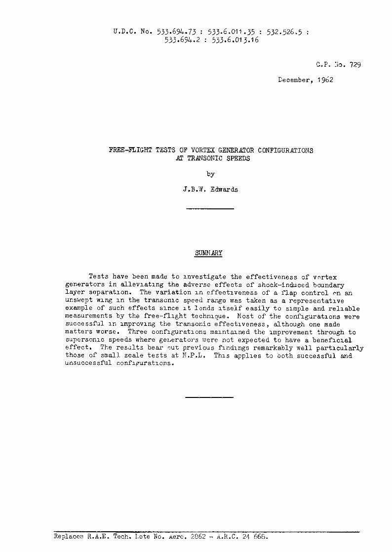
FREE-FLIGHT TESTS OF VORTEX GENERATOR CONFIGURAITIONS AT TRANSONIC SPEEDS
J.B.W. Edwards
SMARY
Tests have been made to uvestigate the effectiveness of vortex generators in allevlatlng the adverse effects of shock-induced boundary layer separation. The variation In effectxveness of a flap control pn an unswept wng in the transonrc speed range was taken as a representative example of such effects since It lends Atself easily to simple and reliable measurements by the free-flight technique. Most of the conflguratlons were successful m unprovlng the transonic effectiveness, although one made matters worse. Three conflguratlons malntazned the improvement through to supersonIc speeds where gelAerators were not expected to have a benefulal effect. The rewlts bear qut previous fx&ngs remarkably well particularly those of small scale tests at N.P.L. This applies to both successful and unsuccessful conflguratlons.
Replaces R.A.E. Tech. Late No. xero. 2C62 - A.H.C. 24 566.
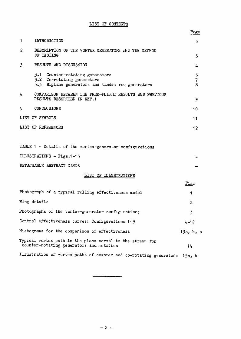
LIST OF CONTENTS
1 INTRODUCTION
2 DESCRIPTION OF THE VORTEX GENERATORS AND THE METHOD OF TESTING
3 RESULTS AND DISCUSSION
3.1 Counter-rotating generators 3.2 cc--rOtatlng generators 3.3 Biplane generators and tandem row generators
4 COMPARISON BETWEEN THE FREE-FLIGHT RESULTS AND PREVIOUS RESULTS DESCRIBED IN ELFF.1
5 CONCLUSIONS
LIST OF SYNBOLS
LIST OF REFERENCES
TABLE1 - Details of the vortex-generator configurations
ILLUSTRATIONS - Figs.l-15
DETACHABLE ABSTRACT CARDS
ai!?
3
9
10
II
12
LIST OF ILLUSTRATIONS
a.
Photograph of a typ1ca.l rolling effectiveness model 1
Wing details 2
Photographs of the vortex-generator oonflgurations 3
Control effectiveness curves: Configurations l-9 4-12
Histograms for the comparison of effectiveness 13a, b, c
Typical vortex path in the plane normal to the stream for counter-rotating generators and notation 14
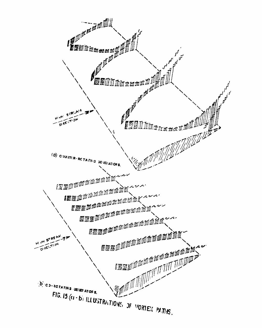
Illustration of vortex paths of counter and co-rotating generators l5a, b
-2-
1 INTRODUCTION
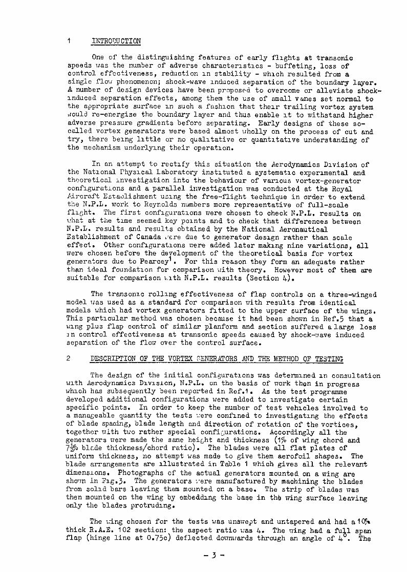
One of the distinguishing features of early flights at trsnsonic speeds was the number of adverse character1stlcs - buffeting, loss of control effectiveness, reduction 1n stability - nh1oh resulted from a single flou phenomenon; shook-wave induced separation of the boundary layer. A number of design devices have been proposed to overcome or alleviate shock- induced separation effects, among them the use of small vanes set normal to the appropriate surface 1n such a fush1on that their trailing vortex system dould re-energise the boundary layer and thus enable 1t to withstand higher adverse pressure gradients before separating. Early designs of these so- called vortex generators were based almost i/holly on the process of cut and try, there being 11ttle or no qualitative or quantitative understanding of the mechanism underlying their operation.
In an attempt to rectify this situation the Aerodynsmics Division of the Nat1onsl l'hys1cal Laboratory instituted a systematic experimental and thooreticnl investigation into the behaviour of various vortex-generator conf1guratlons and a parallel investigation was oonducted at the Royal Aircraft Estaolishment using the free-flight technique in order to extend the N.P.L. work to Reynolds numbers more representative of full-scale flight. The first oonf1gurat1on.s were chosen to check N.P.L. results on what at the time seemed key points and to check that differences between N.P.L. results and results obtained by the National Aeronautical Establishment of Canada $ore due to generator design rather than scale effect. Other conf1guratxns nere added later making nine variations, all were chosen before the development of the theoretical basis for vortex generators due to Pearcey'. For this reason they form an adequate rather than ideal. foundation for comparison with theory. However most of them are suitable for comparison >,1th N.P.L. results (Section 4).
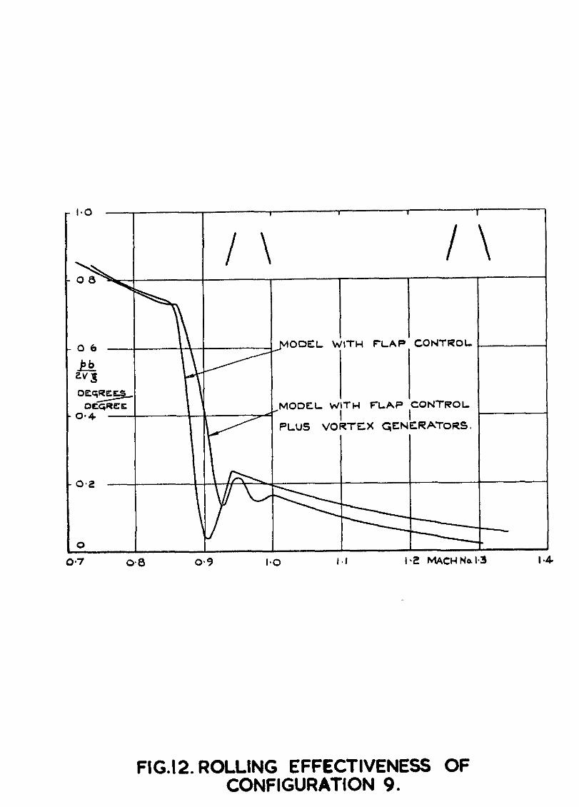
The transon1c rolling effectiveness of flap controls on a three-winged model was used as a standard for comparison with results from identical models which had vortex generators fitted to the upper surface of the wings. This particular method was chosen because it had been shown in Ref.5 that a wing plus flap oontrol of similar planform and section suffered alarge loss 1n control effectiveness at transonic speeds caused by shook--crave induced separation of the flon over the control surface.
2 DESCRIPTION OF THE VORTEX GENERATORS AND THE METHOD OF TESTING
The design of the initial configurations was determined 1n consultation 111th Aerodynamics Division, N.P.L. on the basis of nork thon in progress which has subsequently been reported in Xef.1. As the test progrsmme developed additional configurations were added to investigate certain specific points. In order to keep the number of test vehicles involved to a manageable quantity the tests ::ere confined to investigating the effects of blade spaoing, blade length and direction of rotation of the vortices, together nith two rather special configurations. Accordingly sll the generators were made the ssme height and thickness (170 of wing chord and 7% blade thickness/chord ratio). The blades were all flat plates of uniform thickness, no attempt was made to give them aerofoil shapes. The blade arrangements are illustrated in Table 1 which gives all the relevant dimensions. Photographs of the actual generators mounted on a wing are sho1-m in F1g.3. The generators :'ere manufactured by machining the blades from solid bars leaving them mounted on a base. The strip of blades nas then mounted on the wing by embeating the base in the wing surface leaving only the blades protruding.
The l:ing chosen for the tests iras unswept and untapered and had aI& thick R.A.E. 102 section: the aspect ratio l:as 4. The rring had a full span flap (hinge line at 0.750) deflected donnrrards through an angle of 4'. The
-3-
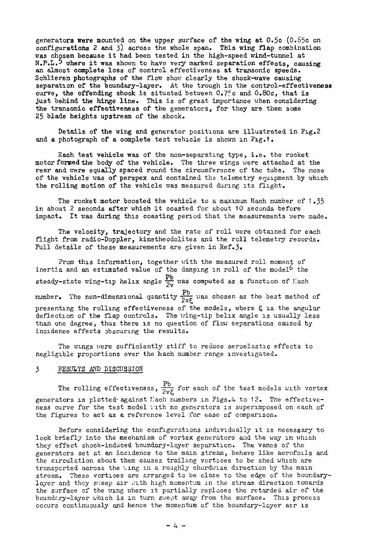
generators were mounted on the upper surface of the wing at 0.5~ (0.6% on configurations 2 and 3) across the whole span. This wing flap combination was chosen because it had been tested in the high-speed wind-tunnel at N.P.L.5 where it was shown to have very marked separation effects, causing an almost complete loss of control effectiveness at transonic speeds. Schlieren photographs of the flow shot clearly the shock-wave causing separation of the boundary-layer. At the trough in the control-effectiveness curve, the offending shock is situated between 0.7:~ and O.BOc, that is just behind the hinge line. This is of great importance when considering the transonic effectiveness of the generators, for they are then some 25 blade heights upstream of the shock.
Details of the wing and generator positions are illustrated in Fig.2 and a photograph of a complete test vehicle is shown in Fig.1.
Each test vehicle was of the non-separating type, i.e. the rocket motorfonnedthe body of the vehicle. The three wings were attached at the rear and were equally spaced round the circumference of the tube. The nose of the vehicle uas of perspex and contained the telemetry equipment by mhxch the rolling motion of the vehicle nas measured during Its flight.
The rocket motor boosted the vehicle to a maximum Mach number of 1.35 in about 2 seconds after which it coasted for about 10 seconds before impact. It ras during this coasting period that the measurements xere made.
The velocity, trajectory and the rate of roll were obtalned for each flight from radio-Doppler, kinetheodolites and the roll telemetry records. Full details of these measurements are given in Ref.3.
Prom this information, together with the measured roll moment of inertia and an estimated value of the damping in roll of the model6 the
steady-state wing-tip helix angle 2 uas computed as a function of Elach
number. The non-dimensional quantity Pb - was chosen as the best method of 2%
presenting the rolling effectiveness of the models, where 5 IS the angular deflection of the flap controls. The liing-tip helix angle 1s usually less than one degree, thus there is no question of flow separations caused by incidence effects obscuring the results.
The wings were sufficiently stiff to reduce aeroelastlc effects to negligible proportions over the hach number range investigated.
3 RESULTS AND DISCUSSION
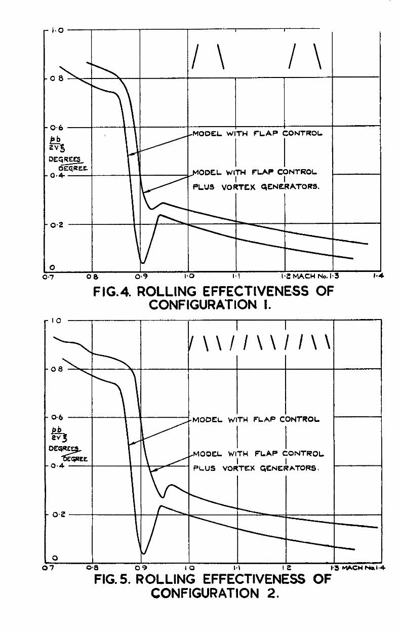
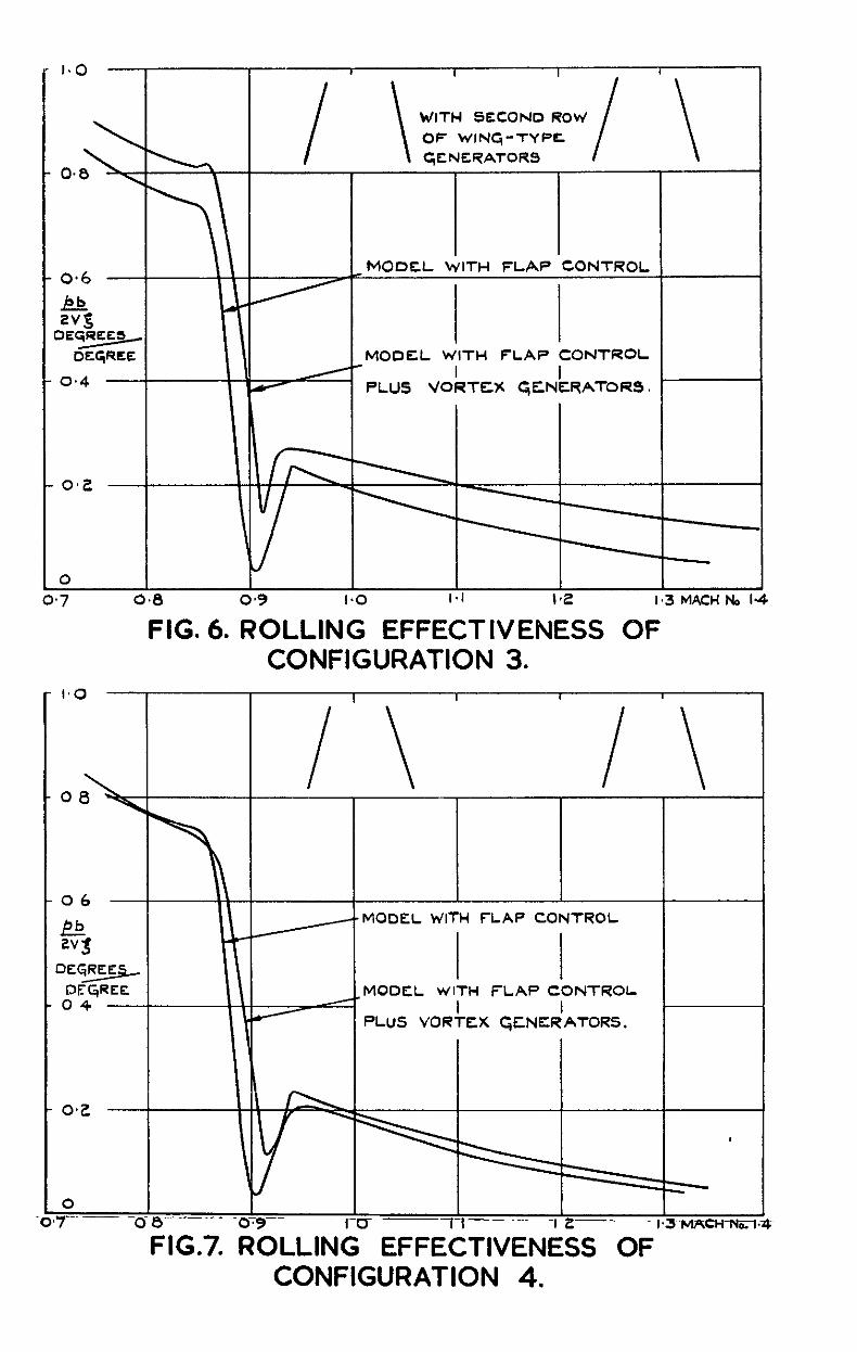
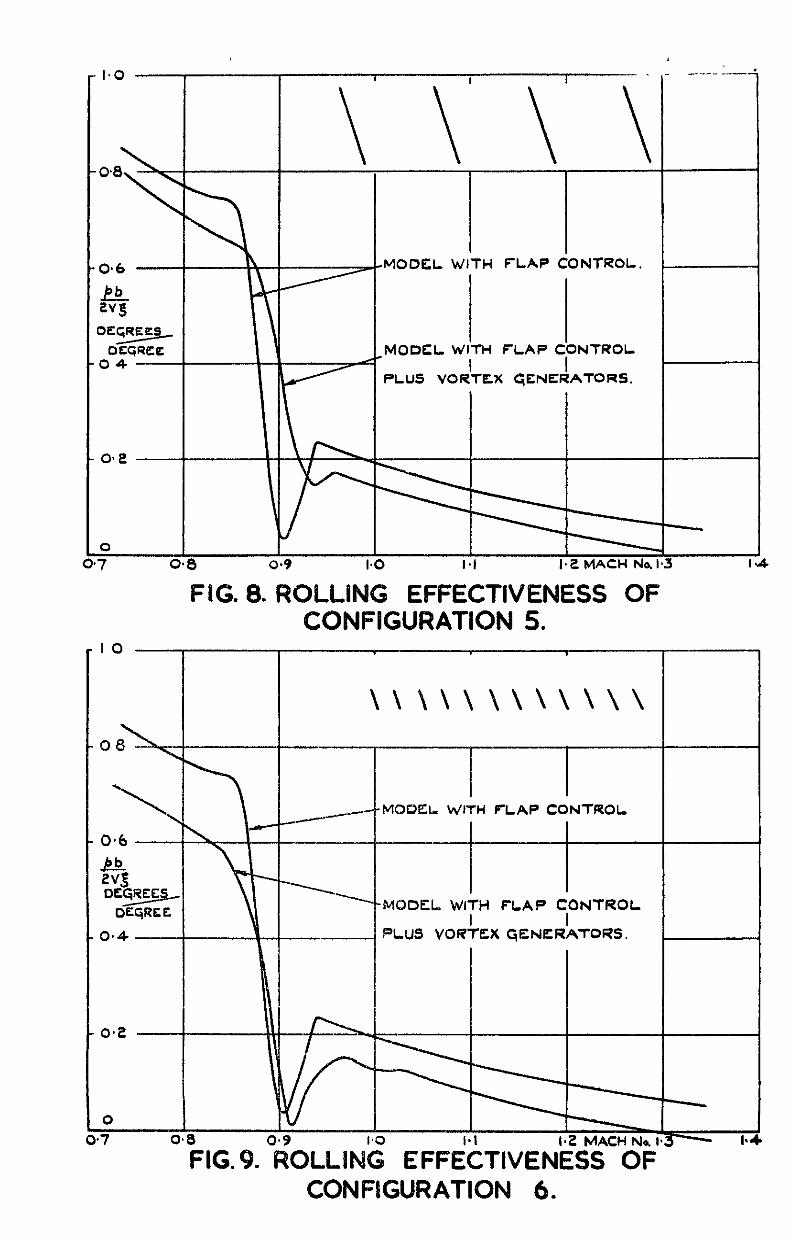
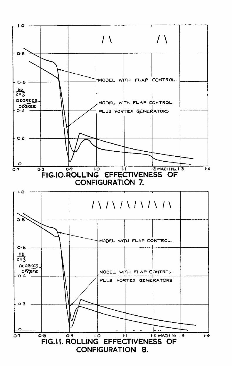
f 0 Pb The rolling erfectiveness, 2vE; - for each of the test models with vortex
generators 1s plotted-against Eiach numbers HI Figs.4 to 12. The effective- ness curve for the test model :-ith no generators is superimposed on each of the figures to act as a reference level for ease of comparison.
Before considering the configurations individually it is necessary to look briefly into the mechanism of vortex generators and the way in urhlch they effect shock-induced boundary-layer separation. The vanes of the generators set at an incidence to the maln stream, behave like aerofolls and the crrculztion about them causes trailing vortlccs to be shed which are transported across the ;.~ng u? a roughly chordulse direction by the main streem. These vortices are arranged to be close to the edge of the boundary- layer and they s:eep wr .!lth high momentum in the stream direction towards the surface of the ning rzhere It partially replxes the retnrded air of the bounder-y-layer lrhich is in turn sweet auey from the surface. This process occurs continuously and hence the momentum of the boundary-layer air IS
-4-
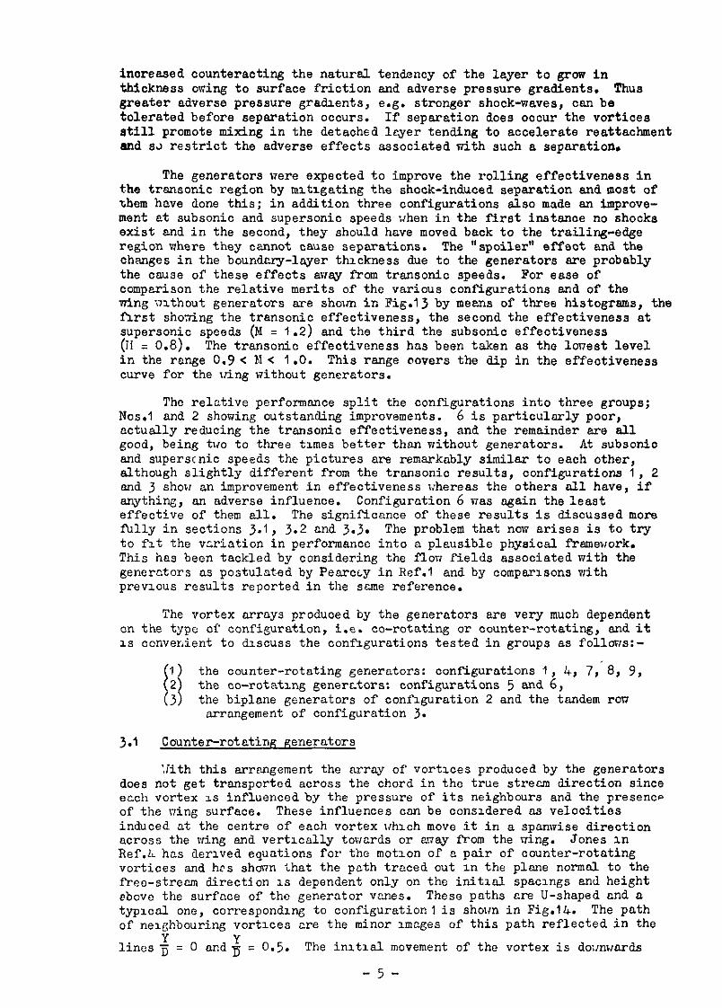
increased counteracting the natural tendency of the layer to grow in thickness owing to surface friction and adverse pressure gradients. Thus greater adverse pressure gradients, e.g. stronger shock-waves, can be tolerated before separation occurs. If separation does occur the vortices atill promote mixing in the detached leyer tending to accelerate reattachment and SJ restrict the adverse effects associated with such a separation.
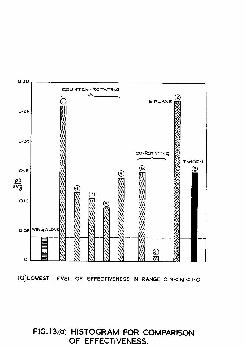
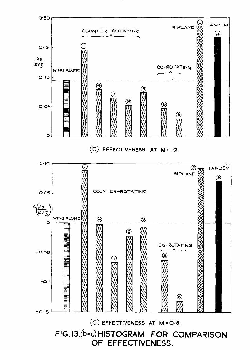
The generators were expected to improve the rolling effectiveness in the trsnsonic region by mltlgating the shock-induced separation and most of them have done this; in addition three configurations also made an improve- ment at subsonic and supersonic speeds xhen in the first instance no shocks exist and in the second, they should have moved back to the trailing-edge region where they cannot Cause separations. The “spoiler” effect and the changes in the boundary-layer thickness due to the generators sre probably the cause of these effects away from trsnsonio speeds. For ease of comparison the relative merits of the various configurations and of the wing nithout generators are sholm in Fig.13 by means of three histogrsms, the first shoting the transonic effectiveness, the second the effectiveness at supersonic speeds (M = 1.2) and the third the subsonic effectiveness (ii = 0.8). The transonic effectiveness has been taken as the lonest level in the range 0.9 < 1~1 < 1 .O. This range (rovers the dip in the effectiveness curve for the uing without generators.
The relative performance split the configurations into three groups; Nos.1 and 2 showing outstanding improvements. 6 is particulsrly poor, cctually reducing the trsnsonic effectiveness, and the remainder are all good, being two to three times better than without generators. At subsonic and superstnic speeds the pictures are remarkably similar to each other, although slightly different from the transonic results, configurations 1, 2 and 3 show an improvement in effectiveness whereas the others sll have, if anything, an adverse influence. Configuration 6 was again the least effective of them all. The significance of these results is discussed more fully in sections 3.1, 3.2 and 3.3. The problem that now arises is to try to fit the vcriation in performance into a plausible physical framework. This has been tackled by considering the florr fields associated with the generctors as postulated by Pearcty in Ref.1 and by comparisons with previous results reported in the scme reference.
The vortex arrays produced by the generators are very much dependent on the type of configuration, i.e. co-rotating or counter-rotating, and it is convenient to discuss the configurations tested in groups as follows:-
‘I
1 the counter-rotating generators: configurations 1, 4, 7, 8, 9, the co-rotating generstors: configurations 5 and 6
(: the biplane generators of configuration 2 and the iandem rou arrangement of configuration 3.
3.f Counter-rotating generators
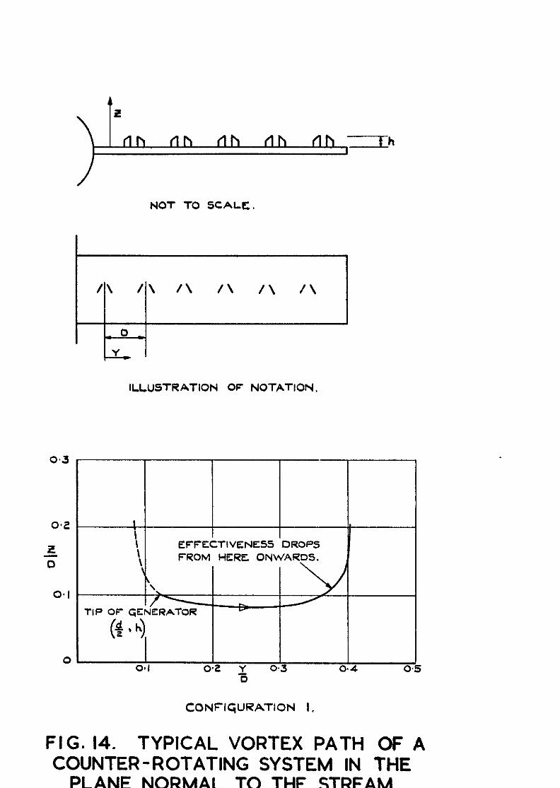
Xth this arrangement the array of vortices produced by the generators does not get transported across the chord in the true stream direction since etch vortex is influenced by the pressure of its neighbours and the presence of the ning surface. These influences can be considered as velocities induced at the centre of each vortex which move it in a spanwise direction across the wing and vertically towards or away from the rring. Jones in Ref.4 hcs derived equations for the motion of a pair of counter-rotating vortices and hrs shoun <hat the pcth traced out in the plane normal to the free-stream direction is dependent only on the initzal spacings and height ebove the surfcce of the generator vcnes. These paths are U-shaped and a typical one, corresponding to configuration 1 is shown in Fig.14. The path of neighbouring vortices cre the minor images of this path reflected in the
lines z = 0 and; = 0.5. The initial movement of the vortex is doxwards
-5-
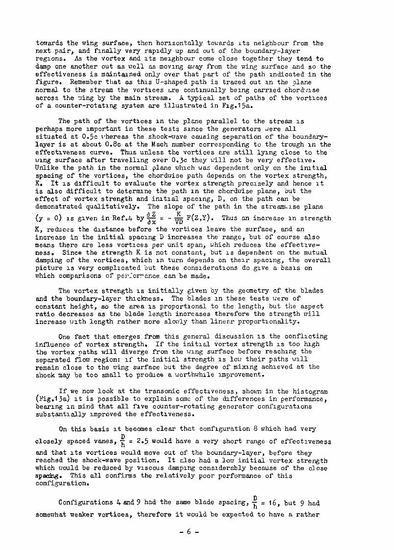
torvards the wing surfaae, then horizontally twards its neighbour from the next pair, and finally very rapidly up and out of the boundary-layer regions. As the vortex and its neighbour come close together they tend to damp one another out as dell as moving away from the wing surface and so the effectiveness is maintained only over that pert of the path indicated in the figure. Remember that as this U-shaped path is traced out in the plane normal to the stresm the vortices are continually being carried chord:ise across the ?ing by the main stream. h typical set of paths of the vortices of a counter-rotating system are illustrated in Fig.15a.
The path of the vortices in the plane parallel to the stream is perhaps more important in these tests since the generators &tere all situated at 0.5~ rPhereas the shock-nave causing separation of the boundary- layer is at about 0.8~ at the Mach number corresponding to the trough in the effeotlveness curve. Thus unless the vortices are still lying close to the wing surface after travelling over 0.3~ they >:ill not be very effective. Unlike the path in the normal plane niuch was dependent only on the initial spacing of the vortices, the chorduise path depends on the vortex strength, IL It is difficult to evaluate the vortex strength precisely and hence it is also difficult to determine the path in the chordnise plane, but the affect of vortex strength and initial spacing, D, on the path can be demonstrated qualitatively. The slope of the path in the streezmise plane
(y = 0) 1s given in Ref.4 by% = - & F(Z,Y). Thus an increase in strength
K, reduces the distance before the vortices leave the surface, and an increase in the initial spacing D increases the range, but of course also means there are less vortices per unit span, ;ihich reduces the effective- ness. Since the strength K is not constant, but IS dependent on the mutual damping of the vortices, which in turn depends on their spacing, the overall picture is very complicated but these considerations do give a basis on which comparisons of perlor?nnce can be made.
The vortex strength is initially given by the geometry of the blades and the boundary-layer thickness. The blades in these tests were of constant height, so the area is proportional to the length, but the aspect ratio decreases as the blade length increases therefore the strength nil1 increase with length rather more slorily than linear proportionality.
One fact that emerges from this general discussion is the conflicting influence of vortex strength. If the initial vortex strength is too high the vortex paths will diverge from the wing surface before reaching the separated flow region: rf the initial strength is lou their paths ~111 remain close to the wing surface but the degree of mixing achieved at the shock may be too small to produce a jrorthwhile Improvement.
If we nom look at the transonic effectiveness, shown in the histogram (Fig.lja) it is possible to explain some of the differences in performance, bearing in mind that all five counter-rotating generator conflguratlons substantially improved the effectiveness.
On this basis it becomes clear that configuration 8 which had very
closely spaced vanes , $ = 2.5 would have a very short range of effectiveness
and that its vortices would move out of the boundary-layer, before they reached the shook-wave position. It also had a ion initial vortex strength which would be reduced by viscous damping considerably because of the close SP=+T. This all confirms the relatively poor performance of this configuration.
Configurations Land9 had the same blade spacing, i = 16, but 9 had
somewhat weaker vortices, therefore it would be expected to have a rather
-6-
longer range of effectiveness so that its vortices would be lower in the boundary-layer at the shock position of the transonic trough and henoe more effective in reducing the effects of the separation. This result is confirmed in Fig.13a. Although a large value ofi implies a long range of effectiveness, the overall amount of vortioity will be rather low since there will be so few vanes across the wing span. Each pair of vortices may well be effective over a local part of the span, but the wide spacing may leave large areas of the wing unaffected by vortices end they therefore show up unfavourably compared to configuration I.
Configuration 1 has the same strength as configuration 9 but a reduced {which would give a rather shorter range of effectiveness but apparently still long enough to reach the shock position and the increased number of vortices gives a good coverage aorosr the wing. The vortex strength seems adequate to give good effectiveness and the overall result was excellent as it had also been found to be in small-scale tests at N.P.L.'
Configuration 7 was similar in performance to configuration 4 and 9 although its initial spacing was like that of configuration 1. It had smeller blades giving vortices of lower strength which should increase the range of effectiveness, but it was shown above that the range was adequate for+ = IO as the additional range from lower vortex strength does not
help further, rather the opposite, since the vortex strength being lower is reflected in a reduced effectiv ness.
A? - This may be
7
gravated by the close- ness of the vanes of each pair
\a- 8.3, (eee Table 1) which may cause a
high initial damping until they move a little farther apart. It might be concluded that configuration 1 was the best as it was a happy medium with regard to e+cing and vortex strength since too great or too little of either produces adverse effects.
At subsonic and supersonic speeds (Figs.ljb and c) only configuration 1 improved the effectiveness, Pb and although the increments in - were similar
2v& to those tranaonically the percentage changes were very much smaller, being within ?I@, compared to several hundred per cent before. The changes must be accounted for by change in the pressure distribution resulting from changed ooundary-leyer thickness and from reduced static pressure between the vortices behind the generators. There will be an opposing positive pressure increment in front of the blades.but for configuration I, the nett result was a gain in rolling effectiveness. The subsonic improvement is easier to understand since conditions at the trailing edge and hence on the under surface of the wing, can be affected by the presence of the generators. No work at N.P.L. was done at We supersonic speeds so no information for comparison is available.
3-2 Co-rotating generators
The induced velocities of a co-rotating system produce a much simpler motion of the in&vidual vortices. Theoretically there is no motion induced in the vertical direction so the vortices remain at their initial height as they traverse the wind chord. There are lateral velocities induced which make each vortex travel on a curved path across the chord. xl1 the vortices travel on parallel paths and thus they remain at the same spacing as the generator blades. A typical set of vortex paths for a co-rotating system is illustrated in Fig.lsb. Nithout the complexity of path associated with the counter-rotating types it is found that the most important factor in the effectiveness of co-rotating generators is the spacing of the vanes. If the vsnes are too close together there will be damping and interference
-7-
effects, and at the other extreme, if the blades are too widely spaced the vortex strength per unit span will be low and so also will their effective-
ness. Earlier work* has shown that a spacing off = 3 is a minimum for the
establishment of a favourable vortex pattern. The optimum spacing may be
slightly larger than! = 4, but anything less than: = 3 would not be
expected to produce a satisfactory pattern. The orderly array of vortices behind co-rotating generators is not maintained at the extremities of the generator row where the end vortex has no neighbour on one side to continue the balancing out of induced velocities. This causes the end vortex to move anay from the surface and spiral round the path of its neighbour with a resulting loss of efficiency.
The two configurations with co-rotating systems numbers 5 and 6 which nere tested bore out previous results. Configuration 5,nhiah had a blade
qlsoingof~ = 5, a little larger than the optimum, was reasonably successful
at transonic speeds although it was not as good as configuration I. This result reproduces remarkably well the comparison between the ssme two configurations in Ref.1, Fig.103. It is interesting to note here that when tested on a smooth aerofoil, i.e. without a deflected flap, the co-rotating
'i enerators show up much better being almost as good as configuration 1 Ref.1, Fig.102).
Configuration 6, with very closely spaced blades, T; = 1.2 was D
expected to show little or no improvement and in fact it reduced the rolling effectiveness throughout the Mach number range. The close spacing produces adverse effects similar to those of closely spaced counter-rotating generators - high viscous damping and mutual interference - so that low energy air swept out of the boundary-layer by one vortex tends to be swept in again by the adjacent ones.
At supersonic speeds both configurations caused reductions in effectiveness consistent rith their blockage effect. In faot for all ConfiguratIons causing a reduction in supersonic effectiveness, the reduction could be correlated to the physical magnitude of their blockage effect, tsken as the projected area of the blades normal to the stream direction.
3.3 Biplane generators and tandem row generators
Biplane generators, the only example of which was configuration 2, consist of a combination of trio counter-rotating systems one being of divergent pairs of vanes as usual, and the second set being convergent pairs of vanes. These component rows are referred to as the dl and d2 system
respectively. The paths of the vortices and hence the effectiveness of this arrangement can be considered in terms of the induced velocities of one system on the other. The Lnduced velocities cause the vortices of the dl
system to move down towards the surface and those of the d system to move 2
away from the surface. The d, system behaves Just like a counter-rotating
system underneath the d2 system. Such an arrangement gives very good mixing
in the boundary-layer as the dl vortices are kept lower in the layer and the
low energy air swept up by these vortices is removed further into the stream by those of the d2 system. Configuration 2, whose d, system alone would
have been reasonably effective, proved to be one of the most successfil tested, both at transonio speeds and supersonic speeds. This is result of the favourable vortex paths and possibly also because of the location of
-a-
the blades at 0.650 rather than a: 0.50, whioh is much closer to the shook position at the trough of the effectiveness curve (0.750 - 0.80). This position for the generators was chosen beoause the biplane system was expeoted to have only a short chordwise range of effectiveness, as a result of increased damping losses owing to the second set of vortices.
The idea behind tandem row generators is to reoreate vortioity at a suitable distance downstream of the first row when the set of vortices from the forward ran have lost their effeotlveness by being damped out or having moved auay from the boundary-layer-c The second row of generators in configuration 3 consisted of wing-type generators mounted at incidence on a central blade forming a T-section arrangement. The front row of generators of configuration 3 was identical with configuration 4 and their transonio effectiveness are very similar, the tandem ran one being slightly better. At supersonic speeds the shock has moved well aft of the seoond row of generators onto the trailing edge and the tandem,row is then very nuoh more effective than configuration 4. In N.P.L. tests of this configuration its effectiveness was as good as that of configuration 1, which is true of the present tests at the higher speeds but not transonically. However, the earlier tests were not done on a zing with deflected flap and this has previously been seen to make a difference (see section 3.2). The present results tend to confirm the theoretical conclusion that the counter-rotating vortices of the fonverd ran lose their effectiveness by moving out of the boundary-layer after travelling a short distance downstream and that the improvements in configuration 3over4 are due to vorticity being re-created where that from the forward ran has become ineffective.
4 COMPARISON BETWEIW THE FREE-FLIGHT RESULTS AND PREVIOUS RESULTS DESCRIBED IN REF.1
Some of the configurations tested were identical with those previously tested and reported in Ref.1. The remainder ere closely related to earlier configurations and comparisons can be drawn for ell configurations, between the measured effectiveness in free-flight and that measured in previous experiments. (All page numbers, Fig. numbers and Table numbers quoted in this section refer to Ref.1.)
Configuration I
This was the ssme as N.P.L. configuration M.2, nhioh was selected, P.1296, as the most consistently successful design for a combination of reasonable level of effectiveness and a large range of effeotiveness. This is shown in Figs.102 and 103 and is well borne out by the R.A.E. tests whiah also shoced it to be one of the best tested.
Configuration 2
Apart from a slight difference in blade length this was like N.P.L. oonfiguration B.3 which has been shown (Fig.103) to be slightly better than M.2. This is consistent tith the present results but some of the effectiveness of No.2 mey be aocounted for by it being set on the wing at 0.650, which is rather neerer the offending interaotion which is thought to be between 0.75~ and 0.8~ at the Mach number corresponding to the dip in the transonio effectiveness curve.
ConfigurationJ
This was the N.P.L. configuration T.l, a tandem row set of generators, which previously (Ng.102) was almost as good as N.P.L. M.2 (R.A.E. No.1). The present tests confirm this at subsonic and supersonic speeds but configuration 3 was not so good at transonio speeds. The previous tests
-9-
were, hoeaver, made on a plain wing without deflected flap and this may be the cause of the difference , since a similar &fference between flapped and plsin wings shorTed up for co-rotating generators (Figs.102 and 103).
Configuration 4
This is configuration 3 without the second row of generators and has also been tested at N.P.L., though the results are not given in Ref.1. It was a little inferior to the tan&m row at transonic speeds which is in agreement with the R9.L. results. The stronger vortices of this configuration over those of No.1 reduce the chordnise range of effectiveness and, together with the rather reduced number of vortices leaving sreas of the ning unaffected, accounts for the rather inferior performance.
ConfY.nuration 5
There mas no exaotN.P.L. equivalent but it is similar to C, end CL,
with which the present results sgree remarkably well. C, and Cq were not so good as Y.2 on a defleoted flap but were as good on a plain aerofoil.
Configuration 6
Although a eimilar configuration has not been tested, experimental work reported in Ref.3 has shown that the blade spacing is well below the minimum for establishing a satisfactory vortex pattern. The reduced effectiveness throughout the Mach number range was to be expected and this oonfiguration has eomfirmed previous evidence on too closely spaced generators.
Confi~ationa 7, 8 and2
No similar configurations have been tested previously but their performances oan be vndaratood by considering the vortex paths.
Configuration 7 has rather weak vortices initially and they may be further reduced in strellgth by high viscous dissipation at first; their subsequent paths should be favourable but their low strength can only give average effeotiveness.
Configuration 8 has very closely spaced pairs of vanes whioh results in the vortices leaving the surface of the wing before they have been oarried far across the chord and this gives a low effectiveness.
Configuration 9, like No.&, has rather too few vortices, and despite the expected good performance of them, probably leaves sreas of the wing unaffected by the vortex mixing and gives only e moderate performance.
5 CONCLUSIONS
Nine vortex-generator configurations have been tested in free-flight. The improvement in rolling effectiveness of a flap control on an unswept wing fitted with generators over that of a similar wing without generators has been taken as a measure of the efficiency of the configurations in alleviating the effects of shock-induced boundary-layer separation,
AU but one of the configurations produced some improvement in transonic control effeotiveness, the best of them almost completely eliminating the loss in effectiveness caused by the separation. Three of the configurations also improved control effectiveness at subsonic and supersonic speeds.
- IO -
An analysis of the paths traced out by the vortices provides some insight into the relative merits of the various configurations. Unfortunately these comparisons are not completely valid beoause the theory describing the paths does not wholly account for the effeot of vortex strength and path shape and hence fails to indioate the influence of vortex height at the shock position downstream of tho generators.
A comparison of the present results with earlier tunnel tests made by N.P.L.’ has been made and good qualitative agreement between them etista.
LIST OF SYMBOLS
b = diameter of the oircle which circumscribes the three wing tips - f’t
0 = wing chord
d 2 distance between vanes of co-rotating generetors, or between vanes of *pair of ocunter-rotating generators
- distances defining the biplane generators as shown in Table I
D = distance between peirs of vanes of oounter-rotating generators
h = vane height
K = vortex strength
1 = vane length
M q Mach number
P = rate of roll - degrees/se0
v = free-stream velocity - ft/seo
X = chordwise oo-ordinate
Y = spanmise’~oo-ordinate
1
with origin at the mid-point between the vanes of a pair of oounter-rotating generators on .- ; ; ; ;g ;;;;
= vertj&l.l &ordinate the wing surface
2 -Fz 5~ ~~~- ~:. --- Lx = iniXdence=of vane to free-streem direotion - degreea .2* .
.: I- &
-1 ;*a = oontr+:defleotion - degrees
-11 -
LIST OF RFFERENCES
No. Author Title, etc.
1 Pearcey,H.H. Shock-u&wed separation and its prevention by design and boundary-layer control. Boundary-layer and flclr control. Ed. G.V. Lochmann. Pergemon Press. 1961.
2 Tanner, L.H. Vortex generators, their desrgn and their effects on Pearcey, H.H. turbulent boundary-layers. Tracy, C.M. A.R.C. 16.487. January, 1954.
3 Laurence, T.F.C. Development of a trensonx research technique using Snan,J. ground-launched rocket-boosted models. Part I.
Control effectiveness measurements. A.R.C. 13,740. July, 1950
4 Jones, J.P. The calculations of the paths of vortices from a system of vortex generators, and a comparison with experiment. A.R.C. C.P. 361. March , 1955.
5 Pearcey, H.H. High speed tunnel tests on a I@ thick R.A.E. 102 . Pankhurst, R.C. tvo-dunens~onal aerofcll with 2% flap: Results at Cash, R.F. zero-incidence 76th 4O flap deflection.
A.R.C. 15,476. September, 1952.
6 De Young, J. Theoretical antisymmetrical span loading for rnngs of arbitrary planform at subsonic speeds. N.A.C.A. Report No. 1056. 1951.
-12 -
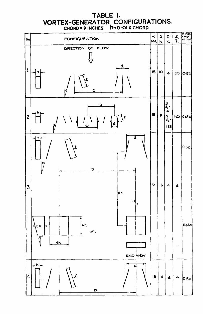
TABLE I. VORTEX-GENERATOR CONFIGURATIONS.
CHORD= 9 INCHES he-01 X CHORD
CONFIG,lJRATIOI’l &cDD L %;
oeq. T; 2 < mwiu
DIRECTION OF FLOW.
‘5 ‘0 4 2.5 0.5
END VIEW
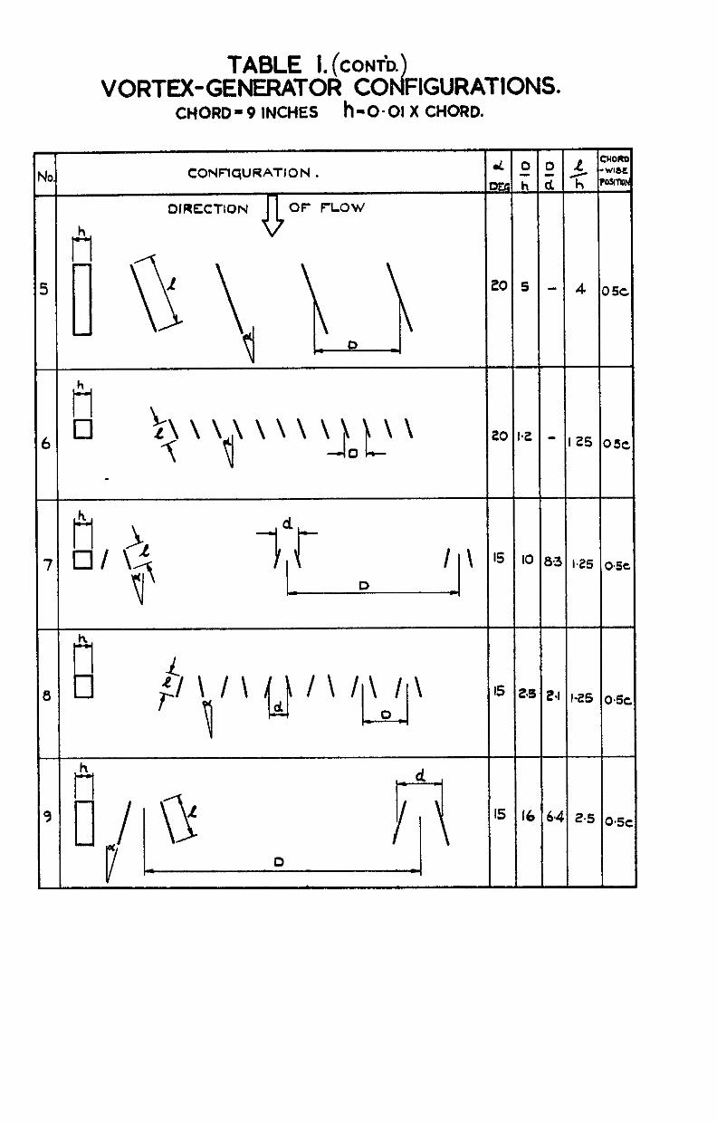
TABLE I. (CONT’D.
VORTEX-GENERATOR CO Id FIGURATIONS. CHORD- 9 INCHES h-o.01 X CHORD.
CONFlqURATION d 0 0 .t? ::: .
OtIkh d. c ro9l-a
DIRECTION OF FLOW
h
t-l
0
h
El
‘5 16 64 2.5 o.5,
.
ALL DIMENSIONS IN INCHES.
NETT ASPECT RATIO 4 NETT ASPECT RATIO 4
CONTROL ANGLE = 4”. ap,- SECTION RAE IO?! IO% t/c
FIG. 2. WING DETAILS.
-0.6 I
-MODEL WITH FLAP CONTROL
)lODfL wl;rW FLAP CTNTROL
PLUS VORTEX qENERATORS.
FlG.4. ROLLING EFFECTIVENESS OF CONFIGURATION I.
MODEL FLAP CbNTROL
FIG. 5. ROLLING EFFECTIVENESS OF CONFIGURATION 2.
I.0 ,I
0 I ,7 0.8
- I I 8
I \ WITH SECOND ROW
OF WING-TYPC
I \ t$ZNERATORS I \
MODEL WITH FLAP CONTROL
MODEL WITH FLAP CONTROL I I
/ PLUS VORTEX C,iZNERATORS.
, I.0 I.1 ls3MACHNo I
FIG. 6. ROLLING EFFECTIVENESS OF CONFIGURATION 3.
T-
. 08 \
06 -
MODEL WITH FLAP CONTROL
PLUS “OR!EIX GENEiATORS.
FIG.7. ROLLING EFFECTIVENESS OF CONFIGURATION 4.
Ia0 - ,- _..___ .--_
MODEL WI’TH FLAP C’ONTROL.
I.,? MACH Na l-3 I
FIG. 8. ROLUNG EFFECTIVENESS OF CONFIGURATION 5.
IO
\\+A\\\\\\\\
/----’
0.6 I \
7 0.S i PC
MODEL WITH FLAP CONTROL
MODEL WITH FLAP CONTROL I
PLUS “OR?rCX QZNERATORS.
102 MACH Na I
b
FIG. 9. ROLLING EFFECTIVENESS OF CONFIGURATION 6.
0
7 00 1.C
YODEL w ‘ITH FLAP CONTROL.
MODEL WITH FLAP CObJTROL
PLUS VORTf X G,f NERATORS
I*t MACH No.
FIGIO. ROLLING EFFECTIVENESS OF CONFIGURATION 7.
.O.---
,7 0.0
FIG.1 1. i
/\!\I\/\/\!\
bLLINt
‘dODEL WITH FLAP CONTROL.
MODEL WITH FLAP C
PLUS VOdTEX GENE IATORS
INTROL
CONFIGURATION 8.
I \ I\
LMODEL +H FLAP: CONTROL }.l 1 \\ \, f
MODEL WiYH FLAP ‘CONTROL
VORTEX GENERAYoRS.
0.7 050 0.9 I *2 MACH No I.3 1.4
FIG.12. ROLLING EFFECTIVENESS OF CONFIGURATION 9.
0 3c
0.2:
0*2c
0.15
.k!? T
0 IO
0.05
0
r3 BIPLANE
CO- ROTATING A
TANDEM
(C)LOWEST LEVEL OF EFFECTIVENESS IN RANGE o-9< MC 1.0.
FIG. 13.(a) HISTOGRAM FOR COMPARISON OF EFFECTIVENESS.
COUNTER- ROTATING
CO- ROTATING
(b) EFFECTIVENESS AT M= 1.2.
0 --------------
-0.05 c~Nc !.a
0
-0 I
8
-0-15
0.10 NDEl
OS05 COUNTER-ROTATINq
(C) EFFECTIVENESS AT M = 0.8.
FIG. 13.(b-c) HISTOGRAM FOR COMPARISON OF EFFECTIVENESS.
NOT TO SCALE.
ILLUSTRATlON OF NOTATION,
o-2
r 0
0.1
0
I I \ EFFECTIVE 1’4555 DROPS \ \ FROM HERE ONWARDS.
\ \
/l TIP OF GENERATOR
(% ’ 9
O*l 0.2 Y 0.3 C a
4 C
CONFIQJRATION I,
5
FIG. 14. TYPICAL VORTEX PATH OF A COUNTER -ROTATING SYSTEM IN THE
PLANE NORMAL TO THE STREAM.
\

r A.RC. C.P. NO. 729 tT.s-3.694.73 : 533.8.011.35 . 532.526.5 FREE-FLIOETT T!GTs OF “ORTEX oENm4TOR CONFiwF!d*ONS AT 5z3.694.2 TFcANsoNiC SPEEDS. Edwards. J. aw. December. 1962. s53.8.013.16
-
A KC. C.P. NO. 729 533.694.73 . 533.6.011.35 5.x526.5
FREE-“.IOHT TESTS OF “ORTEX OENERATOR CONFIGUURATIONS AT 555 694.2 TFSXSONiC SPEEDS. Edwards, J. B w December. 1962 533. 6.013. 16
A.R.C. C.P. NO. 729 533. 694.73 533.6.011.35
I
532 526.5 FREE-KIOHT TESTS OF “ORT!G OENEW.“DR CONFIO”RATIONS AT 533.6942 . TRANSONIC SPEEDS Edwards, J. 8. rl December, 1962 5.33 6.013 16


C.P. No. 729
0 Crown copyrrghr 1966
Pubbshed by
To be purchased from 49 H@h Holborn, London, w c I 423 Oxford Street, London, w 1 13~ Castle Street, Edrnburgh 2
109 St Mary Street, CardlIT Brazennose Street, Manchester 2
50 Fdwfdx Street, Bnslol I 35 Smallbrook, Rmgw,!y, Bnmmgham 5
80 Chichester Street, Brlfdst 1 or through any bookseller
C.P. No. 729 SO Code No 23-9015-29