Embed Size (px)
Citation preview
Join the conversation #AU2017Join the conversation #AU2017
Frame Design and AnalysisManufacturing & Product Design | Inventor
Chris Atherton Sven Eriksson
UK Consulting Services Manager Simulation Service Manager

Agenda:Design Considerations of Frames
Inventor Design AcceleratorsFrame Design in Inventor
Frame Analysis in InventorBeyond Inventor
Chris Atherton
Consultancy Services Manager UK
• Based in Leeds – UK
• Main focuses in Data Management,
Design Automation, Product Design
• BEng (Hons) Aerospace Engineering
“Arguing with an engineer is like wrestling with a pig in mud. After a few minutes you realise the pig likes it” Anonymous
SVEN ERIKSSON
Simulation Services Manager
• Based in Stockholm – Sweden
• Main focuses in all things simulation
• M.SC Navel Architecture, Ship
Building, Mechanics, Stress Analysis
“Life may be one big computer simulation …. It must be the free version!” Anonymous


Frame Design Considerations
▪ Many Types of Frame sections
▪ pipes, rectangular tubes, square tubes,
Angles, Channels, I beam etc
▪ Many Fixing methods:
▪ Weld
▪ Pins
▪ Bolted
▪ Bespoke profiles extruded for lengths

Customer Example: Kone Escalators

Frame Design - Escalator

Stats
• vertical rise 30m
• length of 60m
• Inclined at 30 Deg
• Speed 0.75m/s
High Use
• 300 people every minute
• Low Maintenance
• Maintenance Loads
• weighs over 40 tonnes
40 Year life
• travel the equivalent distance to the moon & back
• Min 20 hours a day, 7 days a week, 364
days a year
Loads
• Carriage has large force
• Set Supports
• Breaking / Startup
• Harsh Environment
Installation Considerations
• Limited time
• Limited Space
• Transportation Loads
Calculations
• Frame analysis
• Key beam loading
• FEA on Joints
• Bolt Analysis
• Fatigue Analysis
Frame Design Considerations: Escalator

Frame Design - Escalator

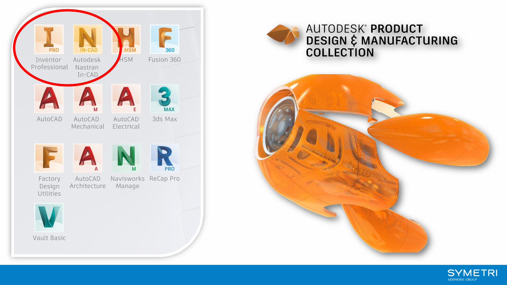
Frame Design | Inventor

Inventor Frame Design
▪ Many Design Accelerators
▪ Utilise Content Centre
▪ Millions of components
▪ Built around standards
▪ Upload your own
▪ Frame tools
▪ Sketch > Place > Treatments
▪ Change > Reuse > Calcs > Documentation
Frame Analysis | Inventor

Frame Design - Escalator

FEA | Nastran In-Cad

▪ Linear Analysis – More Options
▪ Bolted Connections
▪ Buckling
▪ Thermal Stress
▪ Fatigue
▪ Drop-test
▪ Non-Linear –
▪ Beyond Yield Limit
▪ Large Displacement
Some common applicationsto move to Nastran In-CAD

Extending Frame Generator
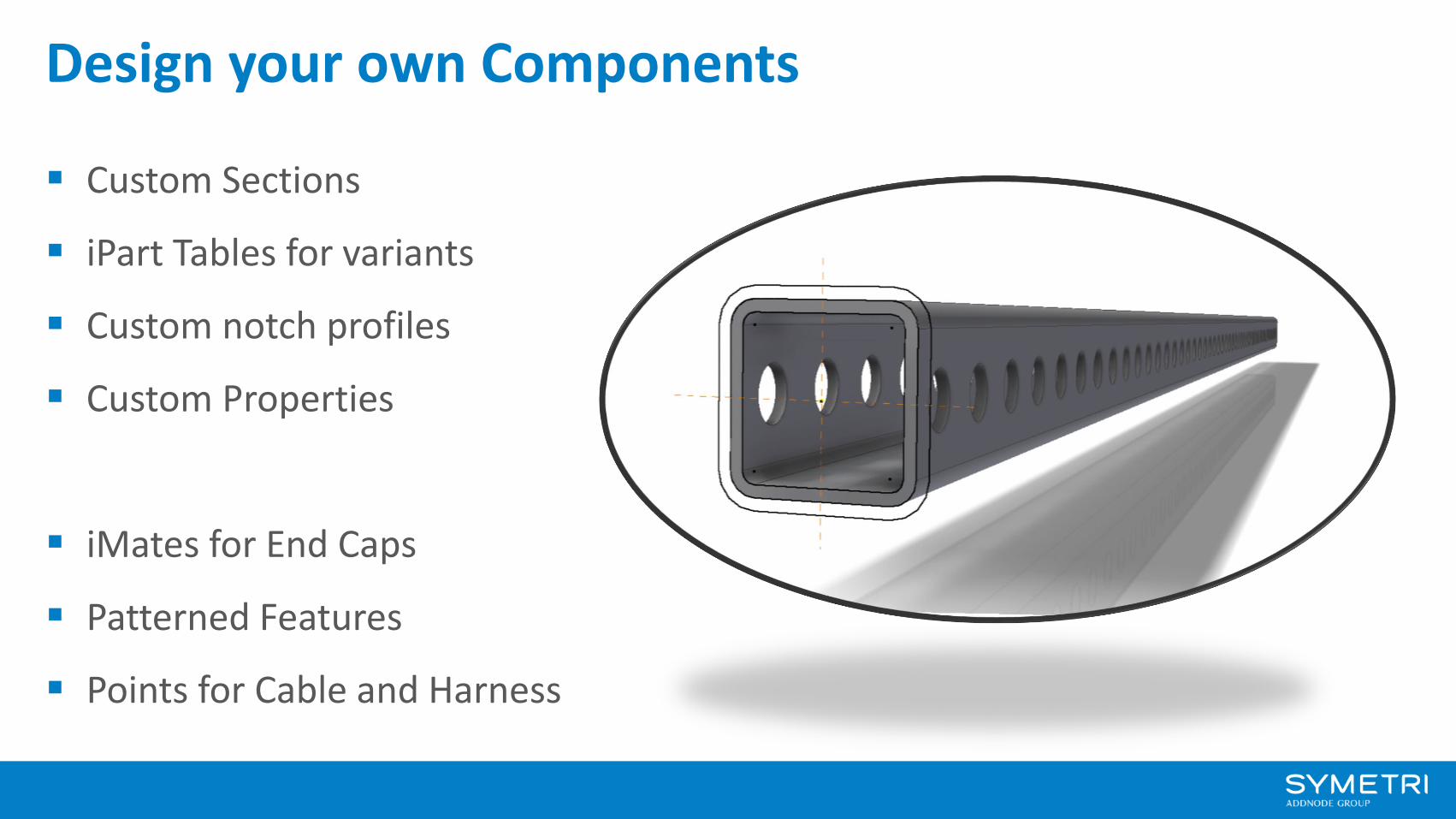
Design your own Components
▪ Custom Sections
▪ iPart Tables for variants
▪ Custom notch profiles
▪ Custom Properties
▪ iMates for End Caps
▪ Patterned Features
▪ Points for Cable and Harness

Chris Atherton
Consultancy Services Manager UK
SVEN ERIKSSON
Simulation Services Manager

Autodesk® Inventor® 2018 Black Book
Up and Running with Autodesk® Inventor® Professional
Autodesk Simhub
Resources
Youtube: SymetriUk

Tuesday8:00 am - 9:00 PM – San Polo 3404, Level 3
MFG123945 - Simultion for ALL – Ease the StressSven Eriksson
9:15 AM - 10:15 AM – Murano 3301B, Level 3
CP125791 - All for Composite Simulation as Manufactured: Autodesk Nastran, Helius PFA, and Moldflow Ecosystem. Jaesung Eom & David Weinbergs
3:45 PM - 4:45 PM – Lando 4305, Level 4
ES125256 - Autodesk Nastran for Inventor: Unlocking DynamicsTony Abbey
Wednesday8:00 AM - 9:00 AM– Delfino 4002, Level 4
ES125249 - Autodesk Nastran for Inventor: Unlocking Nonlinear AnalysesMitch Muncy & Tony Abbey
8:00 AM - 9:00 AM– Lando 4206, Level 4
BLD122332 - Robot Structural Analysis Professional Structural Analysis—from Design to CalculationSafet Iska
1:30 PM - 3:00 PM– Murano 3303, Level 3
DE121004 - Topology Optimization in Autodesk Nastran In-CADDavid Weinberg & Jeff Strain

Autodesk and the Autodesk logo are registered trademarks or trademarks of Autodesk, Inc., and/or its subsidiaries and/or affiliates in the USA and/or other countries. All other brand names, product names, or trademarks belong to their respective holders. Autodesk reserves the right to alter product and services offerings, and specifications and pricing at any time without notice, and is not responsible for typographical or graphical errors that may appear in this document.
© 2017 Autodesk. All rights reserved.