Embed Size (px)
Citation preview
International Journal of Research in Engineering and Science (IJRES)
ISSN (Online): 2320-9364, ISSN (Print): 2320-9356
www.ijres.org Volume 9 Issue 10 ǁ 2021 ǁ PP. 07-40
www.ijres.org 7 | Page
Design and Analysis of Straight Frame over Fish Bellly
Frame
Murari Srikanth 17N36D1510 Master of Technology
Machine Design
A Major project report submitted in partial fulfillment of the requirements for the degree of Master of
Technology in Machine Design
Mr. Harish Assistant Professor
ABSTRACT
The establishment primary engaged in manufacturing heavy commercial vehicles in India are using fish belly
type of Frame assembly (Long member C section). The main aim of project is improve the design performance
of the Fish belly frame by using design software and related analysis software. In this concept we are mainly
comparison between straight frame and fish belly fresh is done by using the “C” section.
This project evaluates a use of straight “C” Frame assembly (Long member C section) to minimize the stress
zone’s at various Frame location. The main aim of the thesis is found which one is highly strength and highly
durable in the analysis point of view.
This project gives a brief idea about few advantage of straight C section over a fish belly section in the aspect of
cost, weight, reliability, Manufacturability and easy of assembly consideration as the current situation in
domestic market comparing the heavy commercial vehicles of Volvo, Scania and Actross as a benchmark.
I. INTRODUCTION
1.1. INTRODUCTION OF CHASSIS FRAME.
Chassis is a major component of a vehicle system. It consists of internal framework that supports man-
made object. It is the under part of the vehicle which consists of frame and running gear like engine,
transmission system, suspension system etc. The automotive chassis is tasked with keeping all components
together while driving and transferring vertical and lateral loads, caused by acceleration, on the chassis through
suspension and the wheels. The key to good chassis design is that further the mass is away from the neutral axis
the more rigid it is. In this project, Pro/ Engineer is the software used for the modelling of the chassis.
The design and analysis of chassis is done by identifying the location of high stress areas. The chassis
design used in this project is the ladder frame chassis. Ladder frame chassis is the simplest and oldest of the
chassis design used in modern vehicular construction. It is originally adapted from the “horse and buggy”style
carriages. as it provides sufficient strength for holding the weight of the components. Ladder frame has several
members that cross link to hold frame rails together.
1.2.THEORY :
CHASSIS:
Chassis consists of the internal framework that supports man made object. It is an essential under part of the
vehicle which consists of the frame and
• Running gear like engine
• Transmission system like clutch and gear
• Suspension system
• Fuel tank
• Brakes
• Steering system
• Road wheels
1.3. CLASSFICATION OF CHASSIS FRAME.
CHASSIS are classified as on the utilization of space:-
Design and Analysis of Straight Frame over Fish Bellly Frame
www.ijres.org 8 | Page
1) CONVENTIONAL CONTROL: - in which engine is mounted in front of the driver’s cabin. This type
of arrangement avoids full utilization of the space.
2) SEMI-FORWARD CONTROL: - in which engine is so mounted that half of it is in the driver’s cabin
whereas the other half is in front, outside the driver’s cabin.
3) FULL-FORWARD CONTROL: - in which the engine is mounted completely inside the driver’s cabin.
Obviously maximum utilization of space is achieved.
CHASSIS are classified on the basis of construction:-
1) CONVENTIONAL CONSTRUCTION: - in which separate frame is used. It is being used presently
only for heavy vehicles.
2) FRAMELESS CONTRUCTIONAL: - in which no separate frame is used. It is used for cars.
1.4. TYPES OF CHASIS:
1 ) L a d d e r F r a m e C h a s s i s
2 ) M u l t i t u b u l a r C h a s s i s
3 ) S p a c e F r a m e C h a s s i s
4 ) M o n o c o q u e C h a s s i s
1. Ladder frame chassis:-
It consists of two symmetrical rails and cross members connecting them. It is being used in trucks .It provides
good beam resistance because of its continuous rails from front to rear, but poor torsion resistance if simple,
perpendicular cross members are used
2. Space frame chassis:-
A space frame or space structure is a truss -like, light weighted rigid structure constructed from
interlocking struts in a geometric pattern. Space frame usually utilize a multidirectional span, and are
often used to accomplish long spans with few supports.
3. Monocoque chassis:-
Monocoque means mono means single and coque means shell. It is constructional technique that supports
structural load by using an object’s exterior, as opposed to using an internal frame or truss that is then covered
with a non-load-bearing skin or coachwork. This technique is also called structural skin, stressed
skin, uni body, unitary construction, or Body Frame Integral
1.4.1. Types of Cross Section used:
a. Channel section
b. I- Beam
c. Hat section
d. Rectangular tubular section
c. Round Tubular section
1.5. TERMS ON CHASSIS FRAME:
a. Wheel base (WB)
b. Front Over hanging (FOH)
c. Rear Over hanging (ROH)
d. Frame width
c. Overall length
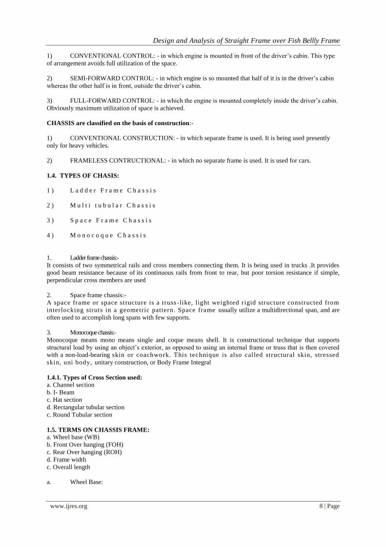
a. Wheel Base:
Design and Analysis of Straight Frame over Fish Bellly Frame
www.ijres.org 9 | Page
The distance between the front and rear axles. Lengthening the wheel base provides a more comfortable ride and
increases interior space, but at the same time, the convenience of a smaller turning radius is lost.
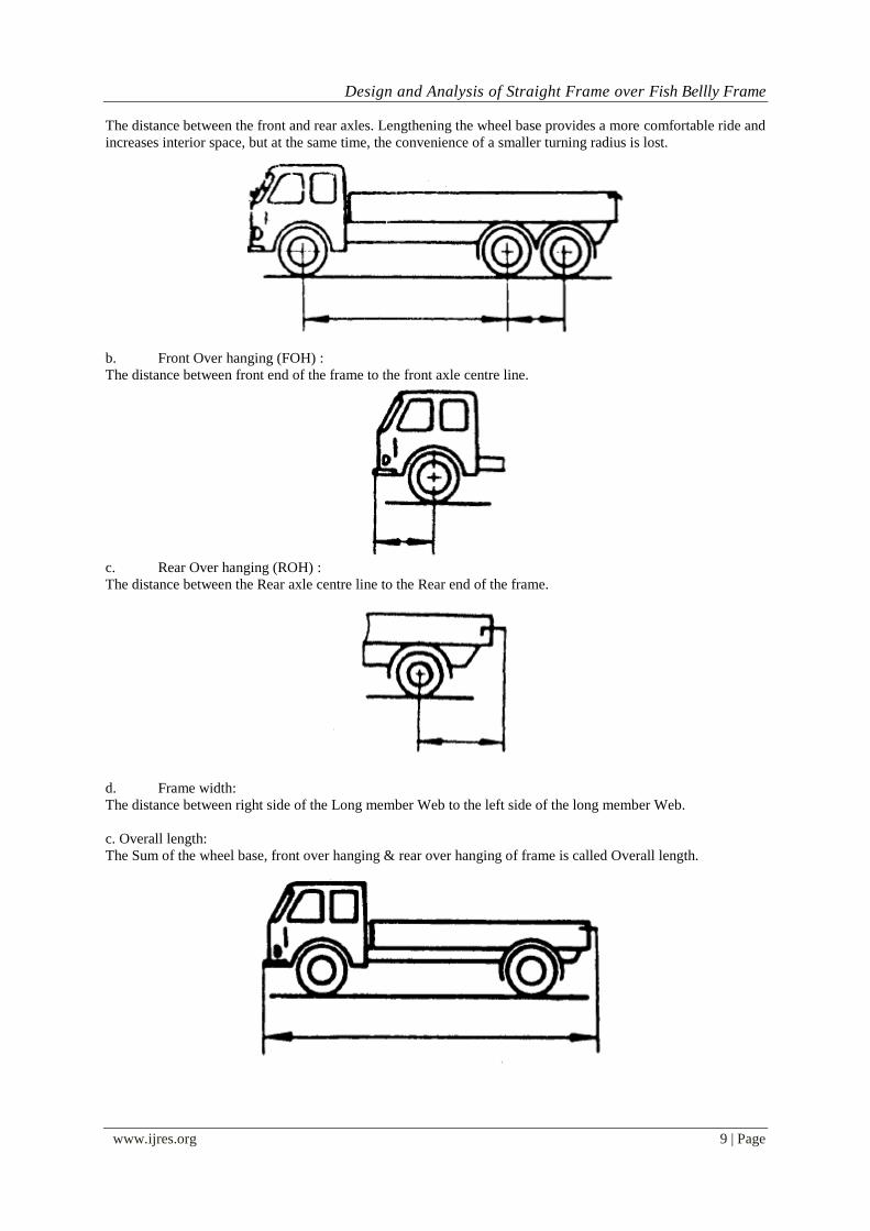
b. Front Over hanging (FOH) :
The distance between front end of the frame to the front axle centre line.
c. Rear Over hanging (ROH) :
The distance between the Rear axle centre line to the Rear end of the frame.
d. Frame width:
The distance between right side of the Long member Web to the left side of the long member Web.
c. Overall length:
The Sum of the wheel base, front over hanging & rear over hanging of frame is called Overall length.
Design and Analysis of Straight Frame over Fish Bellly Frame
www.ijres.org 10 | Page
1.6. BASIC TERMINOLOGY FOR CALCULATION OF CHASSIS FRAME:
1.5.1. TERMS RELATED TO STRENGTH:
a. Section Modulus (Z)
b. Bending Stress
c. Resistance Bending Moment (RBM)
a. Section Modulus (Z) :
Section modulus is a measure of the frame strength based on the height, width, thickness, and configuration of
the side rails (Long member). It is calculated at the point of the maximum stress, which is directly behind the
cab.
b. Bending Stress:
Bending stress is the normal stress that is induced at a point in a body subjected to loads that cause it to bend.
When a load is applied perpendicular to the length of a beam (with two support on each end). Bending moments
are induced in the beam.
c. Resistance Bending Moment (RBM) :
Since the section modulus can only be used to compare frames of like material and yield strength can only
indicate relative strength of identical frames. Some measurement is necessary to compare frames of different
material and different sections. The RBM or Resistance bending moment, can be used for this comparison as it
utilizes section modulus and yield strength.
1.6.1. TERMS RELATED TO DEFLECTION:
a. Moment of Inertia (I)
1.6.2. TERMS RELATED TO APPLIED LOAD:
a. Bending Moment (BM)
a. Bending Moment (BM) :
Summation of all moments acting on the beam (side-rails) at a given point.
II. LITERATURE REVIEW The CC literature is dominated by a few authors and countries. Many of the papers study actual use and
involve practitioners. This limits the places where the studies could have been carried out, as well as their
generalizability. Studies from other countries and of specific services could offer valuable contributions to the
literature.
Many methods are used to collect and analyze data, but two types of studies stand out; statistical
analysis of survey data of citizens’ CC, and case studies of MCM at the organizational level. The studies of CC
appear more harmonized and coherent than those of MCM. Part of this may be because they are carried out by a
small group of authors who cross-reference each other. However, these studies also revolve around one topic –
individual’s CC – use similar variance models and explicitly refer to the same theoretical frameworks to inform
their analyses. There is a strong sense of progress and building on each other’s work, and both empirical and
theoretical contributions are offered. However, they are largely based on survey data from secondary data sets
which the researcher cannot influence. Although a few studies use qualitative studies to inform the survey
creation, CC scholars repeatedly state a need for supplementing surveys through qualitative methods [3, 4, 8, 40,
41, 47].
Methods of direct observation are time consuming to conduct, but they provide valuable contextual
information and could inform areas which have only been slightly touched upon; situational constraints, habits
and how the service in question and its importance to the citizens influence CC. Observations could study an
entire service encounter from the citizens’ point of view and the interplay that takes place between channels
during such an encounter. This would enable CC scholars to explore citizen initiated requests and explain why
these requests occur and gain insight into channel switching and supplementing behavior.
Data on channel traffic could update and supplement the existing knowledge on MCM. Longitudinal
studies of channel traffic could be used to evaluate the effects of MCM instruments on citizens’ channel

Design and Analysis of Straight Frame over Fish Bellly Frame
www.ijres.org 11 | Page
behavior. Most of the existing analyses of channel traffic are based on data which is a decade old, and it is
unknown if the conclusions based on this data still hold up today.
Future CC studies could examine how citizens influence and help each other when interacting with
government organizations. It is striking that the papers in this review focus at only the individual or organization
level. There are no studies of CC at the group level, although both private and public intermediaries are
mentioned at organizational level, and several studies mention that friends and family members can be
intermediaries [25, 32, 44]. Teerling and Pieterson’s process model seems suitable for this task as it illustrates
external parties’ influence on citizens’ CC.
III. METHODOLOGY 3.1 FEATURES OF MODELING AND ANALYSIS SOFTWARES
3.1.1 Features of UG NX
UG NX also known as Unigraphicand it is software suit that developed by the Siemens PLM software. UG NX
is a modern computer aided design (CAD) program. It allows the users to simulate their industrial design
processes from initial concept to product design, analysis, assembly and also maintenance. In this software, it
includes mechanical, and shape design, styling, product synthesis, equipment and systems engineering,NC
manufacturing, analysis and simulation, and industrial plant design
UG NX provides suite of surfacing, reverse engineering, and visualization solutions in order to create, optimize,
modify, and validate complex innovative shape design. For the mechanical engineering point of view, UG NX is
good in creating 3D parts from 3D sketches, sheet metal, composites, moulded, forged or tooling parts and lastly
up to the mechanical assemblies
UG NX is one of the world’s most advanced and tightly integrated CAD/CAM/CAE product
development solutions.
UG NX enables the creation of 3D parts, from 3D sketches, sheet metal, composites, and moulded,
forged or tooling parts up to the definition of mechanical assemblies.
UG NX facilitates collaborative engineering across disciplines around its 3DEXPERIENCE platform,
including surfacing & shape design, electrical, fluid and electronic systems design, mechanical
engineering and systems engineering.
UG NX provides a wide range of applications for tooling design, for both generic tooling and mould&
die.
UG NX uses parametric design principles for solid modeling. UG NX provides mechanical engineers
with an approach to mechanical design automation based on solid modeling technology and following features.
3-D Modeling:
The essential difference between UG NX and traditional CAD system is that models created in UG NX
exist as 3-D solids. Other 3-D models represent only the surface boundaries of the model. Pro/E models the
complete solid. This not only facilitates the creation of realistic geometry, but also allows for accurate models
calculations, like that of mass properties.
PARAMETRIC DESIGN:
Dimensions such as angle, distance and diameter control Pro/E model geometry. Relationships can be
created that allow parameters to be automatically calculated based on the value of other parameters. When the
dimensions are modified, the entire model geometry will be updated according to the relation created.
FEATURE-BASED MODELING:
Models in UG NX are created by building features. These features have knowledge of their
environment and adopt predictably to change. Each feature asks the used for specific information based on the
feature type. For example, a hole has a diameter depth, and placement, while a round has a radius and edges to
round.
ASSOCIATIVITY:
UG NX is a fully-associative system. This means that a change in the design model any time in the
development process is propagated through out the design, automatically updating all engineering delivers,
including assembly, drawings, and manufacturing data. Associativity makes concurrent engineering possible
encouraging change, with penalty; at any point in the development cycle. This enables downstream functions to
contribute their knowledge and expertise early in the development cycle.
APPLICATIONS
UG NX can be applied to a wide variety of industries, from aerospace and defense, automotive, and industrial
equipment, to high tech, shipbuilding.

Design and Analysis of Straight Frame over Fish Bellly Frame
www.ijres.org 12 | Page
3.1.2 Features of HYPERMESH
HYPERMESH software (made for meshing) from Altair is used mesh the solid model. Cad model which is in
IGES format is imported to HYPERMESH. To mesh the geometry use the surface first and then solid. While
meshing some of the quality parameters as to be maintained, those are aspect ratio, skew, jacobian, minimum
element size, warpage.
Hyper Mesh is a market-leading, multi-disciplinary finite element pre-processor which manages the generation
of the largest, most complex models, starting with the import of CAD geometry to exporting ready-to-run solver
file.
3.1.3 CAD Interoperability Hyper Mesh provides import and export support for industry-leading CAD data formats. Moreover, Hyper Mesh
has robust tools to clean up imported geometry to allow for the efficient generation of high-quality meshes.
Boundary conditions can also be applied directly to geometry for automatic mapping to underlying elements.
UG NX and CATIA Composite Link
IGES (import and export)
Intergraph
JT (import and export)
Para solid (import and export)
ProE and CREO
Solid Works
STEP (import and export)
Tribon
FIGURE 3.1 shows hyper mesh shows importing .catpart to hypermesh
Figure 3.1 importing .Hypermesh
FIGURE 3.2 shows hyper mesh shows importing .catpart to hypermesh

Design and Analysis of Straight Frame over Fish Bellly Frame
www.ijres.org 13 | Page
Figure 3.2 shows different stages in done in hyper mesh
Steps involved in pre-processing:-
A) Importing Of Cad
B) Geometry Clean Up
C) Meshing
D) Quality Checks
E) MATERIAL PROPERTIES
F) BOUNDARY CONDITIONS,LOADS
ANALYSIS: - OPTISTRUCT SOLVER
OptiStruct is part of the Hyper Works toolkit, as described earlier this is a finite element solver designed
to solve linear and non-linear simulations. Along with the Hyper Works suite explicit solver, RADIOSS, Hyper
Works can simulate structures, fluid, fluid-structure interaction, sheet metal stamping, and mechanical systems.
(see picture below). To the user the integration is seamless through the run script provided. Based on the file
naming convention, the right executable or combination of executable is chosen
OptiStruct is a full featured solver for linear structural analysis. It supports point (SPC) and multipoint
(MPC) constraint boundary conditions as well as rigid elements and rigid bodies. Alternate coordinate systems
based or the basic system or each other can be defined for easy grid location definition.
Loads can be distributed on the surface of shells and solids as well as along the length of beam elements.
In addition, imposed displacements and inertia relief loading is available. Thermal loads include convection and
heat generation.
OptiStruct supports a full set of elements including solids, shells, beams, rods, bushings, spot welds,
seam welds, joints, point masses and single DOF mass, stiffness and damping. Beams can be defined by area
and inertias, and also by cross sectional dimensions. Moreover, axisymmetric elements and loads are available.
Models can be specified as a collection of parts that are instanced, relocated, and connected.
Additionally, sub-modeling is available for more accurate stress resolution in critical areas. Analysis results,
such as stresses and strains, can be calculated at element centers, Gauss points, and corner points. Also available
are grid point stresses and strains, element forces, and strain energy. Other output types include composite ply
stresses and strains as well as interlinear shear. Multiple composite failure models, such as Tsai-Wu, Hill,
Hoffman, Applied loading, constrain forces, and rigid element forces can also be output. All output is available
in the Altair H3d format as well as the .op2 and .pch file formats.
Figure shows hyper works solver- optistruct loading .fem file

Design and Analysis of Straight Frame over Fish Bellly Frame
www.ijres.org 14 | Page
Figure 3.3 hyper works solver- optistruct loading .fem file
Figure shows progess of analysis solution
Figure 3.4 progress of analysis solution
Post processing with Hyper View
1. Load the .h3d file into Hyper View using Load model
2. Use the Shaded Elements and Mesh lines button to turn the mesh on
3. Use the Contour button and plot Strain Energy
4. Change the traffic light from transient to linear/modal
5. Animate the first mode by clicking the Play button
6. If the deformation is too large change it to Model percent (10%) using the Deformed options
Design and Analysis of Straight Frame over Fish Bellly Frame
www.ijres.org 15 | Page
7. Add more frames and control the speed of the animation using the Animation controls button
8. Step through the modes using load case selector
RESEARCH METHODOLOGY
Following is the research methodology adopted for the problem stated earlier,
Fig 5.1: Flow chart of Research methodology
3.2 Data collection:
Based on the data collected relevant to the work, totally two components are selected with dimensions Data is
taken from Emugenginnering services, suchitracircle, hyderabad
The components selected for study are
1. seat adjustment handle
2. floor support brace
3.3 Modeling of components The following models with different configuration aremodeled using CATIA V5 R20 CAD software.
1. Seat recliner handle
2. floor support brace
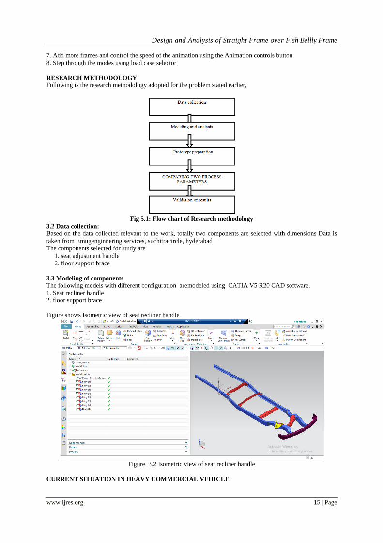
Figure shows Isometric view of seat recliner handle
Figure 3.2 Isometric view of seat recliner handle
CURRENT SITUATION IN HEAVY COMMERCIAL VEHICLE
Design and Analysis of Straight Frame over Fish Bellly Frame
www.ijres.org 16 | Page
Indian costumer expectations are growing day by day as per their requirement & Indian Automotive
sector is also growing in line with the same concept. Based on that in earlier days the Truck features are less
than the present Truck features normally these Feature are based on Different application on Heavy Trucks like.
Tractors
Dumpers or Tippers
Cargos
3.4. TYPES OF TRUCK CHASSIS FRAME
Fish belly type chassis Frame
Straight Chassis Frame
3.4.1. FISH BELLY TYPE CHASSIS FRAME:
Chassis Frame contains Long member & Reinforcement and Cross members. In which long member
having different cross section on various locations based on load conditions & requirement. Those Frames are
called Fish belly frames.
3.4.1.1. ADVANTAGES:
Easy for mass production.
Variable section of Long member “C” can be obtained.
Weight can be reduced due to variable section on Long member
Required section modules can be meet on local area where ever its require.
3.4.1.2. DISADVANTAGES:
Making cost is very high.
Large space is required for manufacturing.
Low load capacity can be occurred.
Not suitable for other manufacturing process like rolling forming.
High maintains cost.
3.4.1.2. MANUFACTURING PROCESS:
Stamping:
This type of fish belly sections is made under Stamping process. The most common method used to form
structural underbody components. The basic stamping operation utilizes a two – piece die set inserted into a
mechanical or hydraulic press. Material placed between the two dies is formed into a part by the load imposed
by the dies is held along the edges of the part by a binder the binder controls the flow of material into the dies
and is critical to the outcome of the finished part.
Most parts require several operations, each one involving a separate operation and die set, to produce a final
part.
3.4.2. STRAIGHT TYPE CHASSIS FRAME:
These chassis Frames are contains same component like fish belly frame but the cross section of Long
member is straight entire length of Chassis frame. Those are called Straight type chassis frame.
3.4.2.1. ADVANTAGES:
High loading capacity.
Flat top ensures easy mounting of load body super structure
& other aggregate mountings.
Frame can be made with roll forming.
Low cost required for manufacturing
Uniform distribution load can be obtained.
Tool can be easily changed for different type of “C” section.
Large volumes can be obtained.
Reduced labor cost and Time Consumption for material handling.
Greater accuracy, uniformity of long member can be achieved with roll forming.
Far longer lengths are achievable.
3.4.2.2. DISADVANTAGES:
More weight as compare to Fish belly frame.
Less fuel efficiency.
3.4.2.3. MANUFACTURING PROCESS:
Design and Analysis of Straight Frame over Fish Bellly Frame
www.ijres.org 17 | Page
Roll forming:
Cold roll forming is an ideal, low cost method of producing shapes with a uniform cross-section. A
sheet or strip of metal is fed longitudinally through a roll forming mill. The mill consists of a train of pairs of
driven roller dies, which progressively form the flat strip until the finished shape is produced.
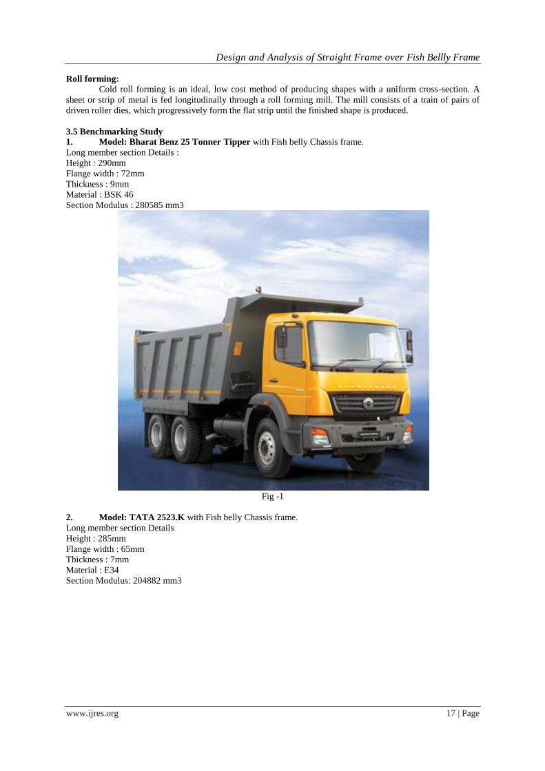
3.5 Benchmarking Study
1. Model: Bharat Benz 25 Tonner Tipper with Fish belly Chassis frame.
Long member section Details :
Height : 290mm
Flange width : 72mm
Thickness : 9mm
Material : BSK 46
Section Modulus : 280585 mm3
Fig -1
2. Model: TATA 2523.K with Fish belly Chassis frame.
Long member section Details
Height : 285mm
Flange width : 65mm
Thickness : 7mm
Material : E34
Section Modulus: 204882 mm3
Design and Analysis of Straight Frame over Fish Bellly Frame
www.ijres.org 18 | Page
Fig - 2
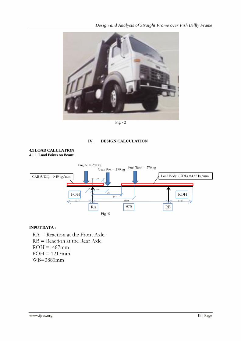
IV. DESIGN CALCULATION
4.1 LOAD CALULATION
4.1.1. Load Points on Beam:
Fig -3
INPUT DATA :
Design and Analysis of Straight Frame over Fish Bellly Frame
www.ijres.org 19 | Page
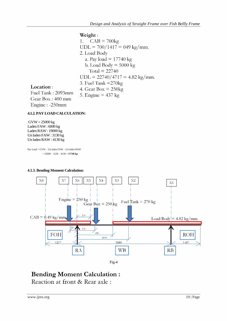
4.1.2. PAY LOAD CALCULATION:
GVW = 25000 kg
Laden FAW : 6000 kg
Laden RAW : 19000 kg
Un laden FAW : 3130 kg
Un laden RAW : 4130 kg
Pay Load = GVW – Un laden FAW – Un laden RAW
= 25000 – 3130 – 4130 = 17740 kg
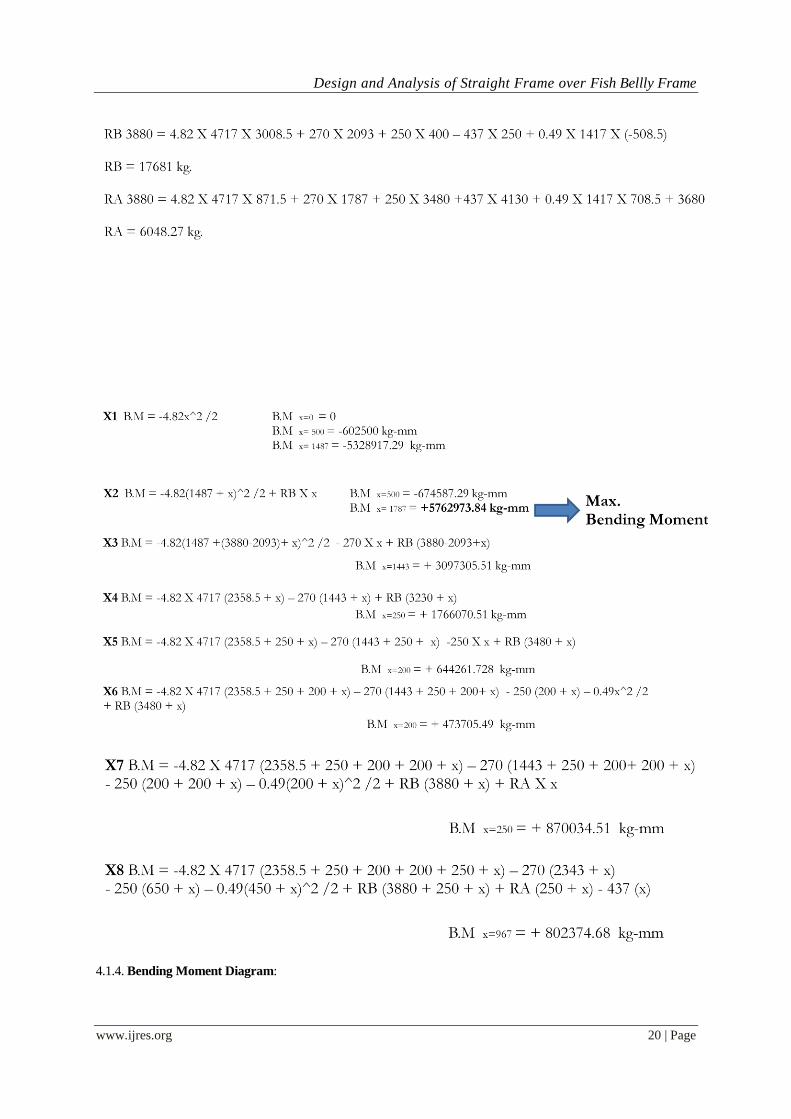
4.1.3. Bending Moment Calculation:
Fig-4
Design and Analysis of Straight Frame over Fish Bellly Frame
www.ijres.org 20 | Page
4.1.4. Bending Moment Diagram:

Design and Analysis of Straight Frame over Fish Bellly Frame
www.ijres.org 21 | Page
Fig-5
4.2. Fish Belly “C” section construction:
4.2.1. Different Section Location on Beam :
Fig -6
Fig-7

Design and Analysis of Straight Frame over Fish Bellly Frame
www.ijres.org 22 | Page
Different Section Dimension on Long member:
Fig-8
4.3. Straight “C” section construction:
Fig -9
4.4. Material Selection :
LOW CARBON OR MILD STEEL IS USED
Advantages of Mild steel:
• It is cheap and malleable.
• Its surface hardness can be increased by the method of carburizing.
• It is not brittle and hence can bear heavy loads without failure.
• Good wear resistance.
• It can be easily machined.
• It is easily available and its composition can be varied to get desired properties.
Design and Analysis of Straight Frame over Fish Bellly Frame
www.ijres.org 23 | Page
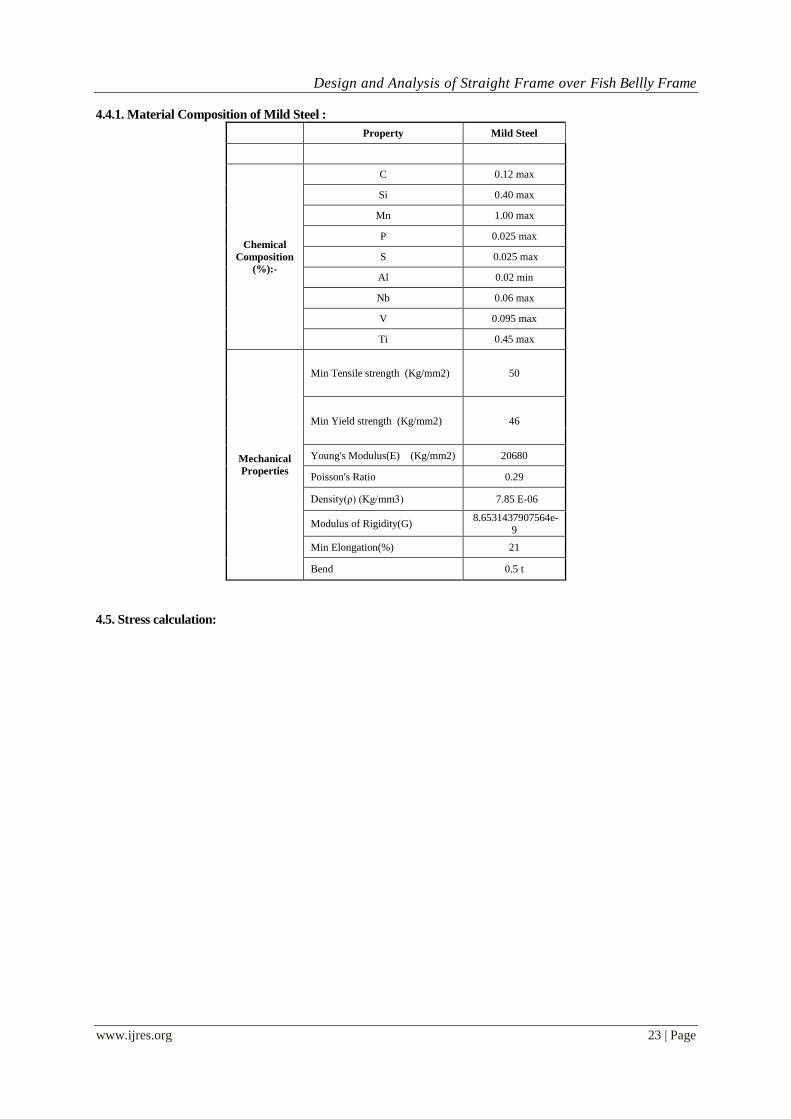
4.4.1. Material Composition of Mild Steel :
Property Mild Steel
Chemical
Composition
(%):-
C 0.12 max
Si 0.40 max
Mn 1.00 max
P 0.025 max
S 0.025 max
Al 0.02 min
Nb 0.06 max
V 0.095 max
Ti 0.45 max
Mechanical
Properties
Min Tensile strength (Kg/mm2) 50
Min Yield strength (Kg/mm2) 46
Young's Modulus(E) (Kg/mm2) 20680
Poisson's Ratio 0.29
Density(ρ) (Kg/mm3) 7.85 E-06
Modulus of Rigidity(G) 8.6531437907564e-
9
Min Elongation(%) 21
Bend 0.5 t
4.5. Stress calculation:
Design and Analysis of Straight Frame over Fish Bellly Frame
www.ijres.org 24 | Page
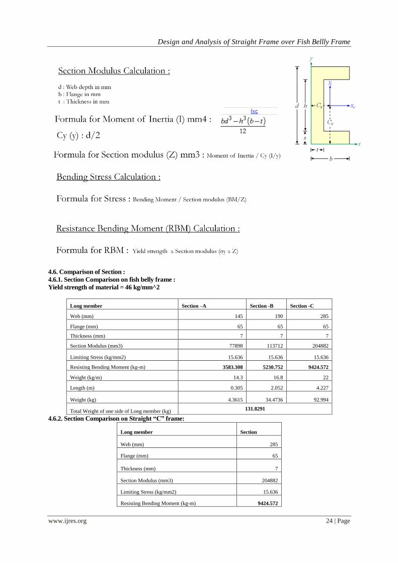
4.6. Comparison of Section :
4.6.1. Section Comparison on fish belly frame :
Yield strength of material = 46 kg/mm^2
Long member Section –A Section -B Section -C
Web (mm) 145 190 285
Flange (mm) 65 65 65
Thickness (mm) 7 7 7
Section Modulus (mm3) 77898 113712 204882
Limiting Stress (kg/mm2) 15.636 15.636 15.636
Resisting Bending Moment (kg-m) 3583.308 5230.752 9424.572
Weight (kg/m) 14.3 16.8 22
Length (m) 0.305 2.052 4.227
Weight (kg) 4.3615 34.4736 92.994
Total Weight of one side of Long member (kg) 131.8291
4.6.2. Section Comparison on Straight “C” frame:
Long member Section
Web (mm) 285
Flange (mm) 65
Thickness (mm) 7
Section Modulus (mm3) 204882
Limiting Stress (kg/mm2) 15.636
Resisting Bending Moment (kg-m) 9424.572
Design and Analysis of Straight Frame over Fish Bellly Frame
www.ijres.org 25 | Page
Weight (kg/m) 22
Length (m) 6.584
Total Weight of one side of Long member (kg) 144.848
26 kg increased on Straight “C” frame over fish belly frame.
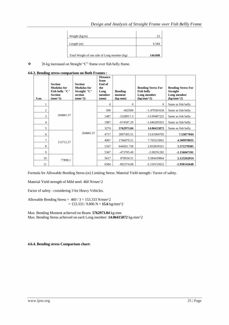
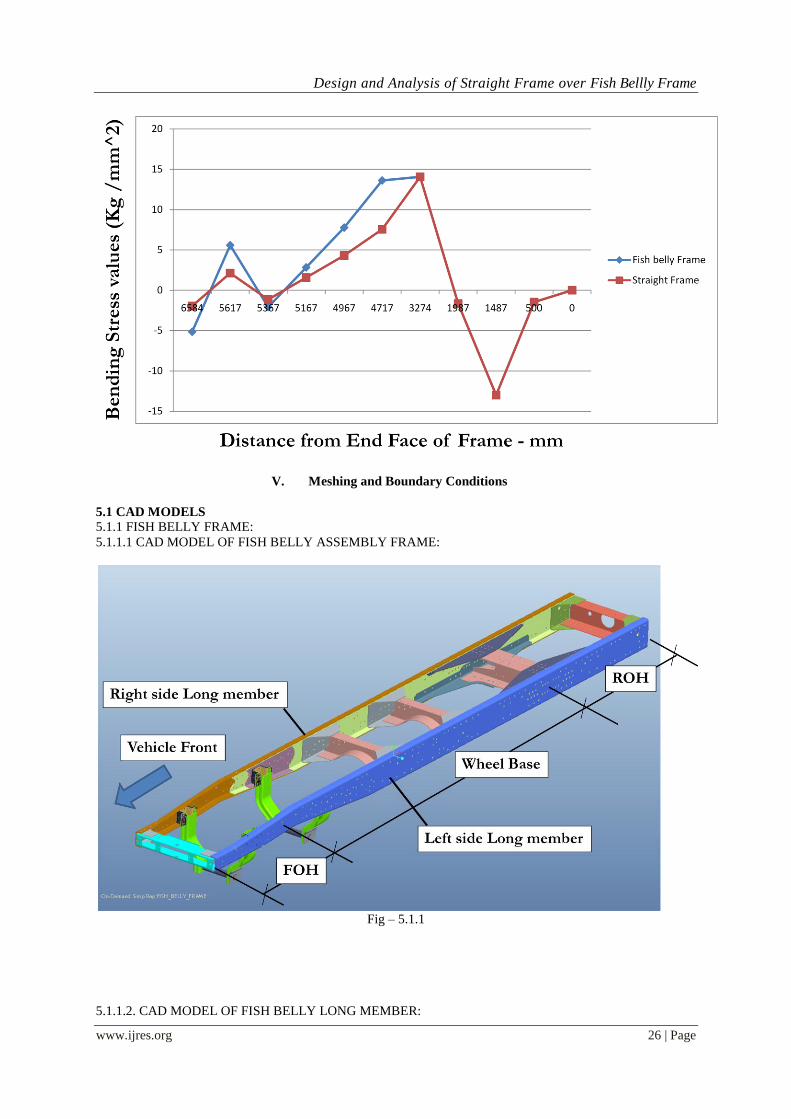
4.6.3. Bending stress comparison on Both Frames :
S.no
Section
Modulus for
Fish belly "C"
Section
(mm^3)
Section
Modulus for
Straight "C"
section
(mm^3)
Distance
from
End of
the
Long
member
(mm)
Bending
moment
(kg-mm)
Bending Stress For
Fish belly
Long member
(kg/mm^2)
Bending Stress For
Straight
Long member
(kg/mm^2)
1
204881.57
204881.57
0 0 0 Same as fish belly
2 500 -602500 -1.470361634 Same as fish belly
3 1487 -5328917.3 -13.00487225 Same as fish belly
4 1987 -674587.29 -1.646285925 Same as fish belly
5 3274 5762973.84 14.06415872 Same as fish belly
6
113712.27
4717 3097305.51 13.61904705 7.55877044
7 4967 1766070.51 7.765523061 4.309978955
8 5167 644261.728 2.832859321 1.572278385
9 5367 -473705.49 -2.08291282 -1.156047101
10 77898.1
5617 870034.51 5.584439864 2.123262014
11 6584 -802374.68 -5.150155652 -1.958142648
Formula for Allowable Bending Stress (or) Limiting Stress: Material Yield strength / Factor of safety.
Material Yield strength of Mild steel: 460 N/mm^2
Factor of safety : considering 3 for Heavy Vehicles.
Allowable Bending Stress = 460 / 3 = 153.333 N/mm^2
= 153.333 / 9.806 N = 15.6 kg/mm^2
Max. Bending Moment achieved on Beam: 5762973.84 kg-mm
Max. Bending Stress achieved on each Long member: 14.06415872 kg-mm^2
4.6.4. Bending stress Comparison chart:
Design and Analysis of Straight Frame over Fish Bellly Frame
www.ijres.org 26 | Page
V. Meshing and Boundary Conditions
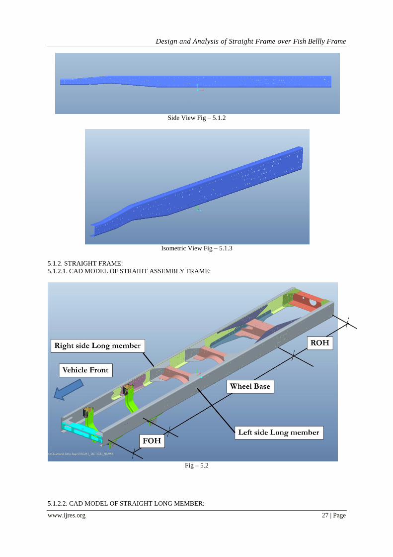
5.1 CAD MODELS
5.1.1 FISH BELLY FRAME:
5.1.1.1 CAD MODEL OF FISH BELLY ASSEMBLY FRAME:
Fig – 5.1.1
5.1.1.2. CAD MODEL OF FISH BELLY LONG MEMBER:
Design and Analysis of Straight Frame over Fish Bellly Frame
www.ijres.org 27 | Page
Side View Fig – 5.1.2
Isometric View Fig – 5.1.3
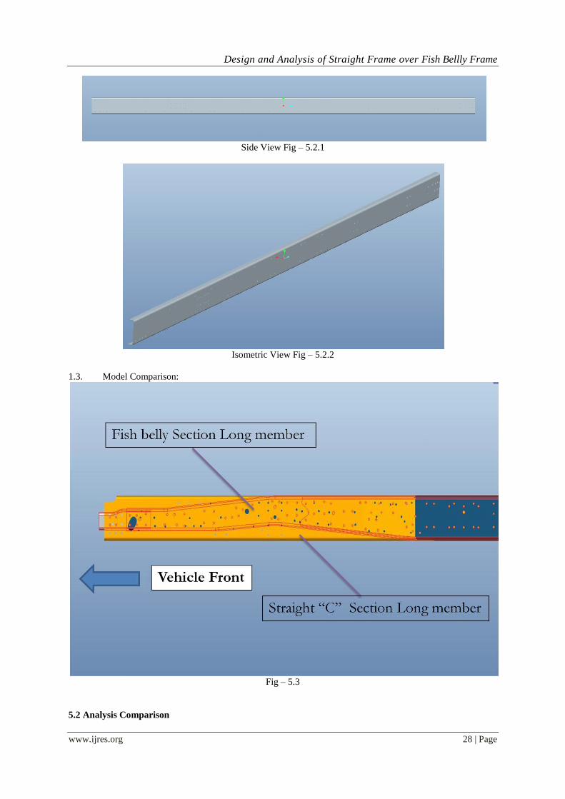
5.1.2. STRAIGHT FRAME:
5.1.2.1. CAD MODEL OF STRAIHT ASSEMBLY FRAME:
Fig – 5.2
5.1.2.2. CAD MODEL OF STRAIGHT LONG MEMBER:
Design and Analysis of Straight Frame over Fish Bellly Frame
www.ijres.org 28 | Page
Side View Fig – 5.2.1
Isometric View Fig – 5.2.2
1.3. Model Comparison:
Fig – 5.3
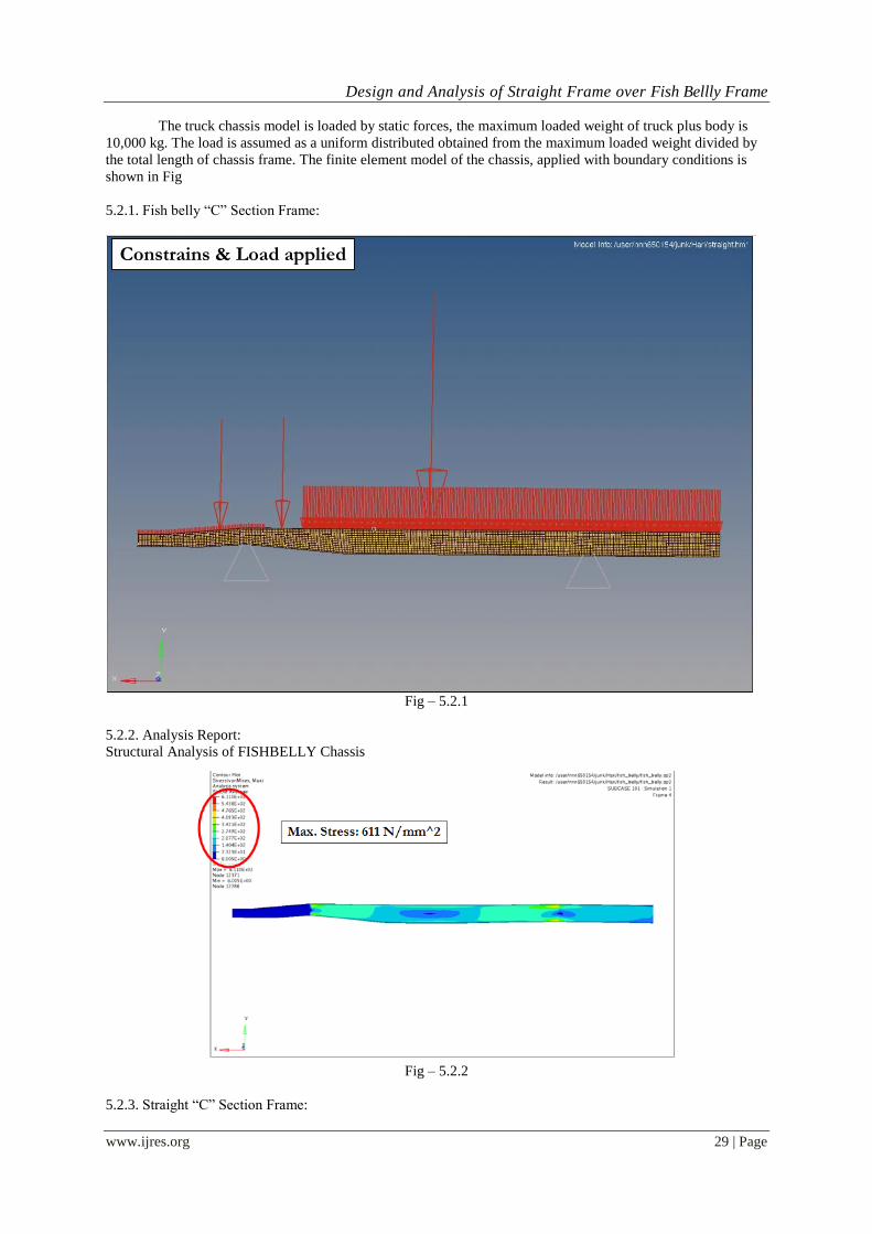
5.2 Analysis Comparison
Design and Analysis of Straight Frame over Fish Bellly Frame
www.ijres.org 29 | Page
The truck chassis model is loaded by static forces, the maximum loaded weight of truck plus body is
10,000 kg. The load is assumed as a uniform distributed obtained from the maximum loaded weight divided by
the total length of chassis frame. The finite element model of the chassis, applied with boundary conditions is
shown in Fig
5.2.1. Fish belly “C” Section Frame:
Fig – 5.2.1
5.2.2. Analysis Report:
Structural Analysis of FISHBELLY Chassis
Fig – 5.2.2
5.2.3. Straight “C” Section Frame:
Constrains & Load applied

Design and Analysis of Straight Frame over Fish Bellly Frame
www.ijres.org 30 | Page
Fig – 19
5.2.4. Analysis Report:
Fig - 20
5.3. FE MESH FILE:-
Max. Stress: 502 N/mm^2
Constructions & Load applied
Design and Analysis of Straight Frame over Fish Bellly Frame
www.ijres.org 31 | Page
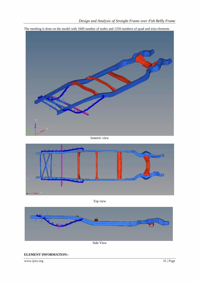
The meshing is done on the model with 1669 number of nodes and 1359 numbers of quad and triea elements
Ismetric view
Top view
Side View
ELEMENT INFORMATION:-
Design and Analysis of Straight Frame over Fish Bellly Frame
www.ijres.org 32 | Page
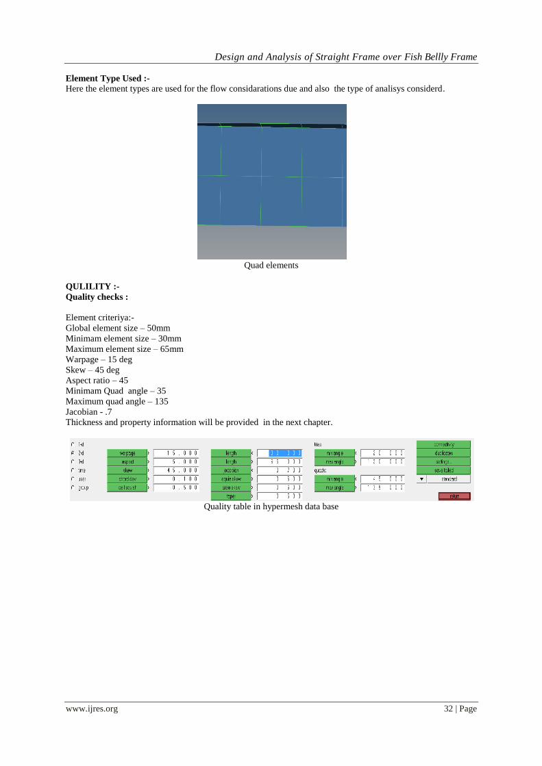
Element Type Used :-
Here the element types are used for the flow considarations due and also the type of analisys considerd.
Quad elements
QULILITY :-
Quality checks :
Element criteriya:-
Global element size – 50mm
Minimam element size – 30mm
Maximum element size – 65mm
Warpage – 15 deg
Skew – 45 deg
Aspect ratio – 45
Minimam Quad angle – 35
Maximum quad angle – 135
Jacobian - .7
Thickness and property information will be provided in the next chapter.
Quality table in hypermesh data base
Design and Analysis of Straight Frame over Fish Bellly Frame
www.ijres.org 33 | Page
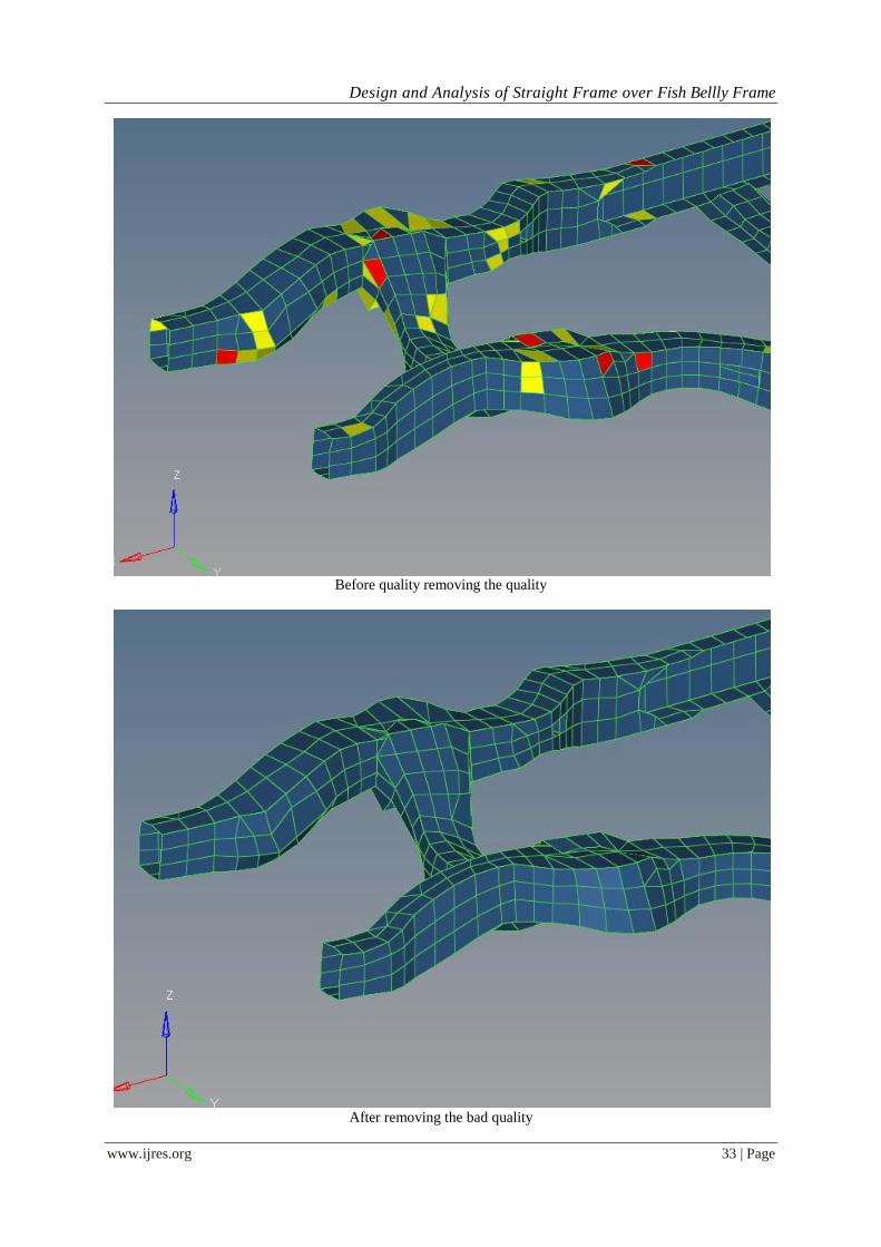
Before quality removing the quality
After removing the bad quality
Design and Analysis of Straight Frame over Fish Bellly Frame
www.ijres.org 34 | Page
Here the above both images are explaned about the quality oparation in prograss
The 1st one showng the while working and the other one is for after removing the quality
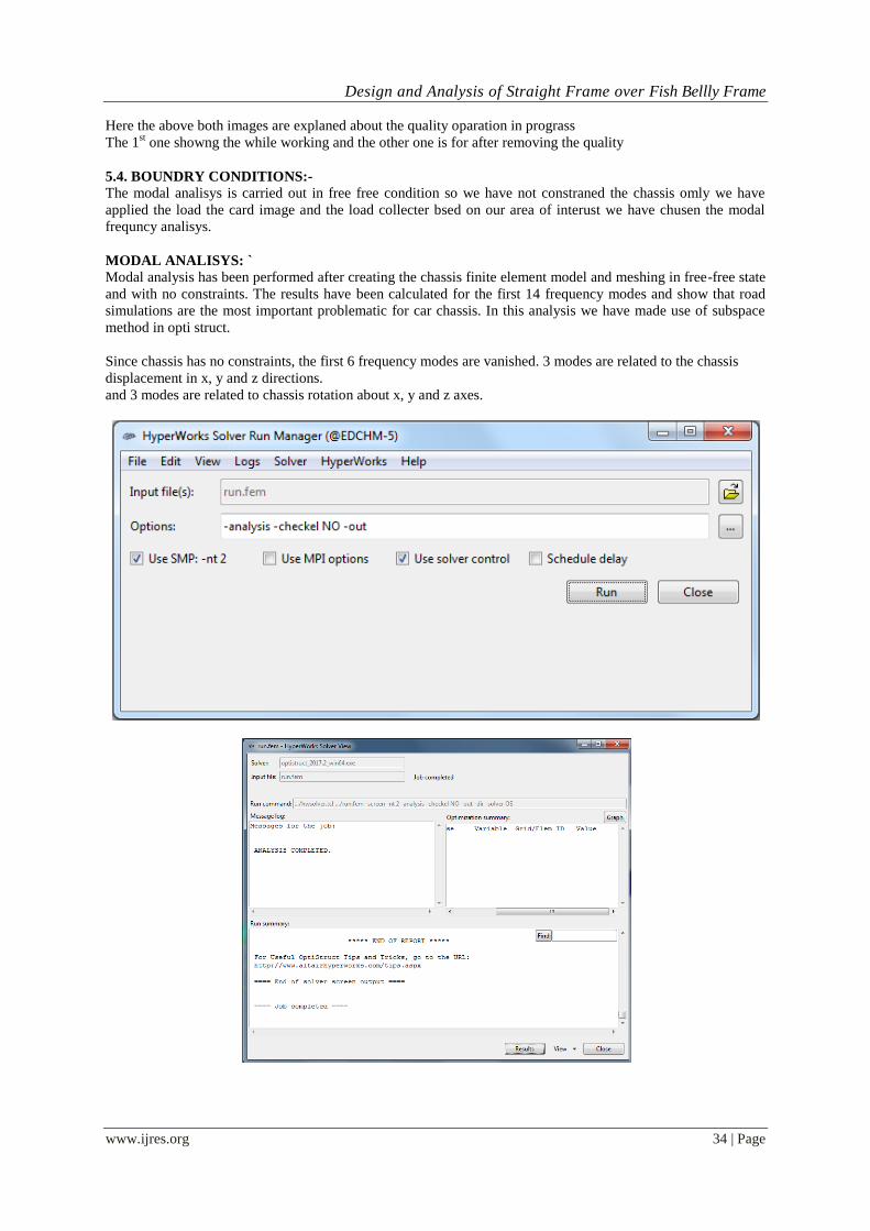
5.4. BOUNDRY CONDITIONS:-
The modal analisys is carried out in free free condition so we have not constraned the chassis omly we have
applied the load the card image and the load collecter bsed on our area of interust we have chusen the modal
frequncy analisys.
MODAL ANALISYS: `
Modal analysis has been performed after creating the chassis finite element model and meshing in free-free state
and with no constraints. The results have been calculated for the first 14 frequency modes and show that road
simulations are the most important problematic for car chassis. In this analysis we have made use of subspace
method in opti struct.
Since chassis has no constraints, the first 6 frequency modes are vanished. 3 modes are related to the chassis
displacement in x, y and z directions.
and 3 modes are related to chassis rotation about x, y and z axes.

Design and Analysis of Straight Frame over Fish Bellly Frame
www.ijres.org 35 | Page
Frequncy with in the structuere
Mode shapes:-
7th mode of frequency:-
Hare the mode shape is bending

Design and Analysis of Straight Frame over Fish Bellly Frame
www.ijres.org 36 | Page
8th mode of frequency:- Bending mode
9th mode of frequency:- Twisting mode

Design and Analysis of Straight Frame over Fish Bellly Frame
www.ijres.org 37 | Page
10th mode of frequency:- Twisting about x direction
11th mode of frequency:-
Design and Analysis of Straight Frame over Fish Bellly Frame
www.ijres.org 38 | Page
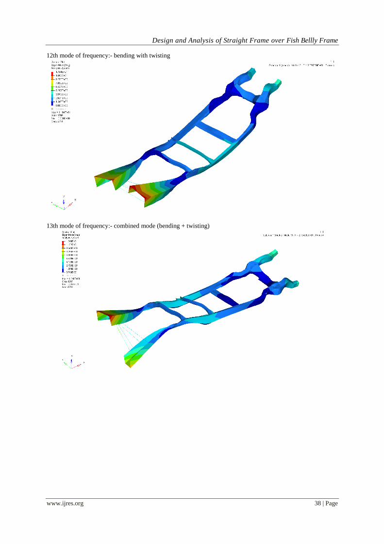
12th mode of frequency:- bending with twisting
13th mode of frequency:- combined mode (bending + twisting)
Design and Analysis of Straight Frame over Fish Bellly Frame
www.ijres.org 39 | Page
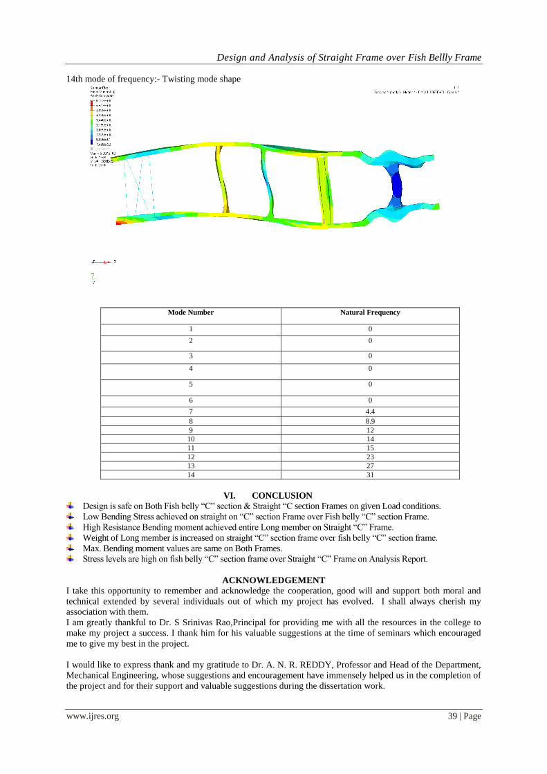
14th mode of frequency:- Twisting mode shape
Mode Number Natural Frequency
1 0
2 0
3 0
4 0
5 0
6 0
7 4.4
8 8.9
9 12
10 14
11 15
12 23
13 27
14 31
VI. CONCLUSION
Design is safe on Both Fish belly “C” section & Straight “C section Frames on given Load conditions.
Low Bending Stress achieved on straight on “C” section Frame over Fish belly “C” section Frame.
High Resistance Bending moment achieved entire Long member on Straight “C” Frame.
Weight of Long member is increased on straight “C” section frame over fish belly “C” section frame.
Max. Bending moment values are same on Both Frames.
Stress levels are high on fish belly “C” section frame over Straight “C” Frame on Analysis Report.
ACKNOWLEDGEMENT
I take this opportunity to remember and acknowledge the cooperation, good will and support both moral and
technical extended by several individuals out of which my project has evolved. I shall always cherish my
association with them.
I am greatly thankful to Dr. S Srinivas Rao,Principal for providing me with all the resources in the college to
make my project a success. I thank him for his valuable suggestions at the time of seminars which encouraged
me to give my best in the project.
I would like to express thank and my gratitude to Dr. A. N. R. REDDY, Professor and Head of the Department,
Mechanical Engineering, whose suggestions and encouragement have immensely helped us in the completion of
the project and for their support and valuable suggestions during the dissertation work.
Design and Analysis of Straight Frame over Fish Bellly Frame
www.ijres.org 40 | Page
I offer my sincere gratitude to my Internal guide Mr. Harish, Asst. Professor of Mechanical Engineering who
has supported me throughout this project with her/his patience for her valuable guidance and encouragement
during my dissertation work.
I would also like to thank our M.Tech Coordinator Mr. Damodar Reddy and the supporting staff of the
Department of Mechanical Engineering and all other departments who have been helpful directly or indirectly in
making the project a success.
I would also like to thank all the supporting staff of the Department of Mechanical Engineering and all other
departments who have been helpful directly or indirectly in making the project a success.
I am extremely grateful to my Parents and Friends for their blessings and prayers for my completion of project
that gave me strength to do my project.
References [1]. Abhishek Singh, et al, “Structural Analysis of Ladder Chassis for Higher Strength”, International Journal of Emerging Technology
and Advanced Engineering, ISSN: 2250-2459, Volume 4, Issue 2, February 2014.
[2]. Patel Vijaykumar, et al, “Structural Analysis of Automotive Chassis Frame and Design Modification for Weight Reduction”,
International Journal of Engineering Research & Technology, ISSN: 2278-0181, Volume 1, Issue 3, May 2012.
[3]. Vishal Francis, et al, “Structural Analysis of Ladder Chassis Frame for Jeep Using Ansys”, International Journal of Modern
Engineering Research, ISSN: 2249-6645, Volume 4, Issue 4, April 2014. [4]. Monika S.Agarwal, et al, “Finite Element Analysis of Truck Chassis”, International Journal of Engineering Sciences & Research,
ISSN: 2277-9655, December 2013.


![Numerical simulations of holographic spatiospectral traces ... · Information from a Single Hologram (STRIPED FISH) [39,40]. STRIPED FISH uses a single camera frame to record multiple](https://img.pdfslide.us/doc/110x75/5d2a158e88c9936e158c82d5/numerical-simulations-of-holographic-spatiospectral-traces-information-from.jpg)